Table of Contents
Quick Links
Table of Contents

Related Manuals for YOKOGAWA PBDH1000


Summary of Contents for YOKOGAWA PBDH1000
- Page 1 User’s Manual Model 701924 PBDH1000 Differential Probe IM 701924-01E 7th Edition...
- Page 2 Contact Us If you want to resolve a technical support issue or need to contact YOKOGAWA, please fill out the inquiry form on our website. https://tmi.yokogawa.com/contact/ PIM 103-06E...
-
Page 3: List Of Manuals
4th Edition: November 2015 5th Edition: October 2017 6th Edition: June 2021 7th Edition: March 2022 7th Edition: March 2022 (YMI) All Rights Reserved, Copyright © 2008 Yokogawa Electric Corporation All Rights Reserved, Copyright © 2015 Yokogawa Test & Measurement Corporation IM 701924-01E... -
Page 4: Checking The Contents Of The Package
Checking the Contents of the Package The following accessories are included. If some of the contents are not correct or missing or if there is physical damage, contact the dealer that you purchased them from. • Probe unit: • Attachments: 1 set (see below) •... - Page 5 Checking the Contents of the Package Attachment Item Quantity 10-cm pair leads 5-cm pair leads Red micro clip Black micro clip 6-cm ground extension lead Contact, heat-shrink tube 1, 2 1 pack (10 each) Flanged input pin Retaining cover Straight pin Angled pin Spring-type straight pin Spring-type angled pin...
-
Page 6: Safety Precautions
To use this product correctly and safely, the general safety precautions described herein must be observed during all phases of operation. YOKOGAWA assumes no liability for the customer’s failure to comply with these requirements. This manual is part of the product and contains important information. - Page 7 If the signal cable is torn and the inner metal is exposed or if a color different from the outer sheath appears, stop using the cable. Do not disassemble or modify Do not disassemble or modify the product. YOKOGAWA assumes no liability if you disassemble or modify the product. CAUTION Protective structure The product is not dust or water resistant.
- Page 8 Si le câble de signal est coupé et que le métal interne est exposé ou si une couleur différente de la gaine extérieure apparaît, arrêtez d’utiliser le câble. Ne démontez ou modifiez pas Ne démontez ou modifiez pas le produit. YOKOGAWA n’assume aucune responsabilité si vous démontez ou modifiez le produit. IM 701924-01E...
- Page 9 Safety Precautions ATTENTION Structure de protection Le produit n’est pas résistant à la poussière ou à l’eau. Ne l’utilisez pas dans des zones très poussiéreuses ou près de l’eau. Environnement d’utilisation et de stockage Évitez d’utiliser ou de stocker le produit dans un environnement qui ne répond pas aux spécifications, comme la lumière directe du soleil, les températures et l’humidité...
-
Page 10: Regulations And Sales In Various Countries And Regions
This product complies with the WEEE marking requirement. This marking indicates that you must not discard this electrical/electronic product in domestic household waste. When disposing of products in the EEA or UK, contact your local Yokogawa office in the EEA or UK respectively. *EEA: European Economic Area Authorized Representative in the EEA (AR) Yokogawa Europe B.V. -
Page 11: Conventions Used In This Manual
Conventions Used in This Manual Improper handling or use can lead to injury to the user or damage to the instrument. This symbol appears on the instrument to indicate that the user must refer to the user’s manual for special instructions. The same symbol appears in the corresponding place in the user’s manual to identify those instructions. -
Page 12: Table Of Contents
Contents List of Manuals ........................i Checking the Contents of the Package ................ii Safety Precautions ......................iv Regulations and Sales in Various Countries and Regions ..........viii Conventions Used in This Manual ................... ix Product Overview ......................1 Features ..........................1 Component Names ......................2 Usage Precautions ......................3 Operating Procedures .......................4 Product Specifications ....................12... -
Page 13: Product Overview
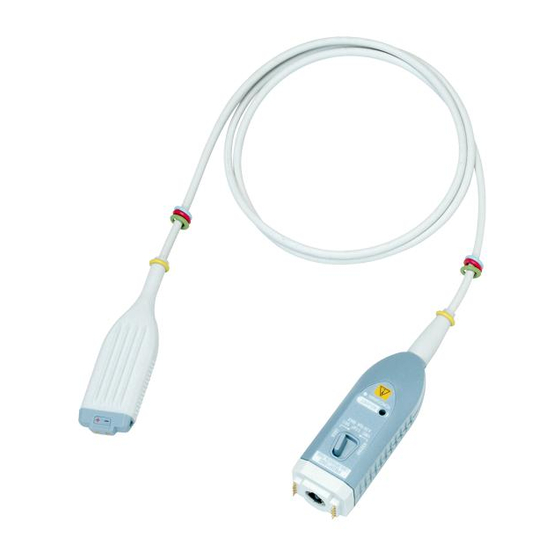
Product Overview The PBDH1000 Differential Probe is a 1-GHz bandwidth, differential-input, active probe that is used in combination with a digital oscilloscope that has a YOKOGAWA probe interface (hereafter referred as digital oscilloscope with a probe interface). To use the probe, you simply connect it to a BNC input terminal on a digital oscilloscope with a probe interface. -
Page 14: Component Names
Component Names Cable Probe head Add various attachments, connect to circuit under test Probe interface To digital oscilloscope input Latch release lever Variable resistor for adjusting offset voltage Output terminal Probe head Cable Interface spring pin Probe interface Connects to a digital oscilloscope input. Interface spring pins When the probe output terminal is connected, these pins touch the pad on the oscilloscope interface board. -
Page 15: Usage Precautions
Usage Precautions WARNING Use this probe only with YOKOGAWA’s oscilloscopes with probe interface. Even with YOKOGAWA’s oscilloscopes, this probe can be used only when specified as a connectable accessory. Also, use this probe only with standard or optional accessories sold separately. -
Page 16: Operating Procedures
Operating Procedures Preparation Have the probe and a digital oscilloscope with a probe interface ready. Insert the probe interface completely into the oscilloscope input, and confirm that the BNC connector and interface pin are securely fastened. You will hear the latch click when the connectors lock into place. When you connect the probe to a digital oscilloscope with a probe interface, the probe’s attenuation ratio and input coupling are set automatically. - Page 17 Operating Procedures Attachment Handling Connect attachments that are suitable for the item that you want to measure to the signal input terminals illustrated below. Select attachments from the following list (see page 9 for attachment application examples). • 5-cm pair lead Can connect directly to a pin header or the item you want to measure.
- Page 18 Operating Procedures Creating an Extension Lead You can create your own extension lead using the accessory kit. At the Circuit-under-Test End Pass the lead wire through a heat-shrink tube for a contact. Crimp or solder the lead wire’s core wire to the contact. Cover the contact with the heat-shrink tube, and then apply heat with a drier to fix the tube in place.
- Page 19 Operating Procedures Probe-Head End Pass the lead wire through the heat-shrink tube. * The heat-shrink tube for the probe-head end is not included. It must be obtained separately. Solder the lead wire’s core wire to the flanged input pin. Cover the flanged input pin with a heat-shrink tube, and then apply heat with a drier to fix the tube in place.
- Page 20 Operating Procedures Attaching the Retaining Cover Pass the flanged sections of the two input pins through the center retaining-cover holes, and place the input pins on the holders on either side. Flange Align the + and − markings on the retaining cover to those on the probe head, and attach the retaining cover to the probe head. Check that the retaining cover’s left and right latches are securely locked.
- Page 21 Operating Procedures How to Use the Ground Extension Lead Example Ground terminal Ground extension lead Connecting the probe ground terminal to the common ground on the circuit under test using the ground extension lead may reduce noise when measuring low-frequency signals. CAUTION Connect the ground extension lead only to the common ground.
- Page 22 Operating Procedures Example 10-cm pair lead with micro chip 5-cm pair lead Pin (straight, angled, spring-type straight or angled) IM 701924-01E...
- Page 23 Operating Procedures Warm-up and Offset Adjustment Warm-up Immediately after connecting the probe, the heat emitted by the probe itself causes the offset voltage to drift. Warm up the probe for at least 30 minutes after applying power to stabilize the probe. Offset Adjustment You can turn the offset voltage adjustment variable resistor on the probe interface by using an appropriate adjustment driver (see page 2 for details) to...
-
Page 24: Product Specifications
Product Specifications Electrical Specifications (The electrical specifications are based on standard operating environment after 30-minute warm-up.) Frequency bandwidth DC to 1 GHz (–3 dB or higher) Attenuation ratio 50:1 DC voltage accuracy ±2 % of differential input voltage (at 50 Ω load) Input capacitance Approx. 1.1 pF (relative to ground, typical value Input resistance 1 MΩ ± 3% (relative to ground) Output impedance... - Page 25 Product Specifications WARNING As the frequency of the input signal increases, the maximum input voltage of the probe decreases. French AVERTISSEMENT Lorsque la fréquence du signal d'entrée augmente, la tension d'entrée maximale de la sonde diminue. Input voltage range Vin- Negative signal input terminal Use it within this range.
- Page 26 EU RoHS Directive compliant 1 Test conditions Frequency bandwidth limit 20 MHz, using a digital oscilloscope with the input impedance set to 50 Ω, and both plus and minus probe tip inputs connected (terminated) to 50 Ω. 2 For conformity to environmental regulations and/or standards other than EU, contact your local Yokogawa office (PIM 113-01Z2). IM 701924-01E...
-
Page 27: Appendix 1 Frequency Characteristics Of Each Attachment
Appendix 1 Frequency Characteristics of Each Attachment The probe’s frequency characteristics vary depending on the attachment that is used and how the lead wires are connected. The frequency characteristics when using a typical attachment are given below. The frequency characteristics for the case when pair leads or pair leads and micro clips are used have been measured with the two lead wires connected in a parallel manner. - Page 28 Appendix 1 Frequency Characteristics of Each Attachment When using a 5-cm pair lead 5-cm Pair lead 1000 Frequency [MHz] When using a 5-cm pair lead with micro clip 5-cm Pair lead with Micro-clip 1000 Frequency [MHz] App-2 IM 701924-01E...
- Page 29 Appendix 1 Frequency Characteristics of Each Attachment When using a 10-cm pair lead 10-cm Pair lead 1000 Frequency [Hz] When using a 10-cm pair lead with micro clip 10-cm Pair lead with Micro-clip 1000 Frequency [MHz] App-3 IM 701924-01E...
-
Page 30: Appendix 2 Input Equivalent Circuit And Dc Voltage Accuracy
Appendix 2 Input Equivalent Circuit and DC Voltage Accuracy Input equivalent circuit Positive signal input terminal Approx. 1.1 pF 1MΩ Approx. 1.1 pF 1MΩ Negative signal (–) input terminal Conceptualization of DC Voltage Accuracy Input voltage Maximum operating input voltage Tolerance Positive input Vin+...