Panasonic TX-32LM70FA Service Manual
Hide thumbs
Also See for TX-32LM70FA:
- Operating instructions manual (32 pages) ,
- Service manual (42 pages)
Table of Contents
Quick Links
Service Manual
Specifications
(Information in brackets [ ] refers to model 26´´)
Power Source:
220-240V AC, 50Hz
Power Consumption:
121 [92W]
Stand-by Power
Consumption:
1W
Aerial Impedance:
75Ω unbalanced, Coaxial Type
Receiving System:
PAL-B/G/I, D/K,
SECAM B/G, D/K, L/L'
PAL-525/60 (AV only)
M.NTSC (AV only)
NTSC (AV only)
Receiving Channels:
VHF E2-E12
VHF H1-H2 (ITALY)
VHF A-H (ITALY)
VHF R1-R2
VHF R3-R5
VHF R6-R12
UHF E21-E69
CATV (S01-S05)
CATV S1-S10 (M1-M10)
CATV S11-S20 (U1-U10)
CATV S21-S41 (Hyperband)
Operating Conditions:
5°C ÷ 35°C
Temperature:
5% ÷ 90% RH (non-condensing)
Humidity:
Intermediate Frequency:
Video/Audio
Video
38,9MHz, 33,9MHz
Audio
33,4MHz (B/G), 33,16MHz (A2)
33,05MHz (NICAM B/G, D/K, L)
32,4MHz (D/K), 32,66MHz (CZ STEREO)
40,4MHz (L'), 39,75MHz (L'NICAM),
32,35MHz,32,9MHz (NICAM)
Colour
34,47MHz (PAL)
34,5MHz, 34,65MHz (SECAM)
38,3MHz, 38,15MHz (SECAM L')
Terminals:
AV1 IN
Video (21 pin)
Audio (21 pin)
RGB (21 pin)
AV1 OUT
Video (21 pin)
Audio (21 pin)
All manuals and user guides at all-guides.com
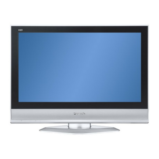
Colour LCD Television
1V p-p 75Ω
500mV rms 10kΩ
0,7V p-p 75Ω
1V p-p 75Ω
500mV rms 1kΩ
GLP21MA Chassis
AV2 IN
Video (21 pin)
Audio (21 pin)
RGB (21 pin)
S-video IN
(21-pin)
AV2 OUT
Video (21 pin)
Audio (21 pin)
AV3 IN
S-Video IN
(4-pin)
Audio (RCAx2)
Video (RCAx1)
HDMI1,HDMI2
Type A Connector
COMPONENT YUV
Video (RCAx3)
AUDIO IN
Audio (RCAx2)
(for YUV, HDMI1)
AUDIO OUT
Audio (RCAx2)
LCD screen:
L5EDD8Q00036
1366 x 768 XGA, 16:9
Visible Diagonal 800mm
Audio Output:
2x10W RMS
8Ω impedance
Headphones:
3,5mm, 8Ω Impedance
Accessories
supplied :
Remote Control
2 x R6 (UM3) Batteries
Dimensions:
Height:
Including TV stand
615mm
[525mm]
TV set only
563mm
[473mm]
Net weight:
16kg
Specifications are subject to change without notice.
Weights and dimensions shown are approximate.
ORDER No. PCZ0709120CE
TX-32LM70FA
TX-32LM70LA
TX-32LM70PA
TX-26LM70FA
TX-26LM70LA
TX-26LM70PA
TX-R32LM70A
TX-R26LM70A
1V p-p 75Ω
500mV rms 10kΩ
0,7V p-p 75Ω
Y: 1V p-p 75Ω
C:0,3V p-p 75Ω
1V p-p 75Ω
500mV rms 1kΩ
Y: 1V p-p 75Ω
C:0,3V p-p 75Ω
500mV rms 10kΩ
1V p-p 75Ω
Y:1V p-p 75Ω
±
Pr:
0,35V[ p-p] 75Ω
±
Pb:
0,35V[ p-p] 75Ω
500mV rms 10kΩ
500mV rms 1kΩ
[L5EDD6Q00027]
[660mm]
Width:
Depth:
791mm
248mm
[657mm]
[216mm]
791mm
107mm
[657mm]
[107mm]
[12,5kg]
Table of Contents

Related Manuals for Panasonic TX-32LM70FA


Summary of Contents for Panasonic TX-32LM70FA
- Page 1 All manuals and user guides at all-guides.com ORDER No. PCZ0709120CE Service Manual Colour LCD Television TX-32LM70FA TX-32LM70LA TX-32LM70PA TX-26LM70FA TX-26LM70LA TX-26LM70PA TX-R32LM70A TX-R26LM70A GLP21MA Chassis Specifications (Information in brackets [ ] refers to model 26´´) Power Source: 220-240V AC, 50Hz...
-
Page 2: Table Of Contents
All manuals and user guides at all-guides.com Contents SAFETY PRECAUTIONS ........... 3 BLOCK DIAGRAMS..........12 GENERAL GUIDE LINES........3 PARTS LOCATION........... 15 TOUCH – CURRENT CHECK....... 3 REPLACEMENT PARTS LIST........16 PREVENTION OF ELECTROSTATIC DISCHARGE SCHEMATIC DIAGRAMS ......... 28 (ESD) TO ELECTROSTATICALLY SENSITIVE (ES) A-BOARD (1 OF 5) SCHEMATIC DIAGRAM .. -
Page 3: Safety Precautions
All manuals and user guides at all-guides.com Safety Precautions General Guide Lines When servicing, observe the original lead dress. If a short circuit is found, replace all parts which have been overheated or damaged by the short circuit. After servicing, see to it that all the protective devices such as insulation barriers, insulation papers shields are properly installed. -
Page 4: Prevention Of Electrostatic Discharge
All manuals and user guides at all-guides.com Prevention of Electrostatic Discharge (ESD) to Electrostatically Sensitive (ES) Devices Some semiconductor (solid state) devices can be damaged easily by static electricity. Such components commonly are called Electrostatically Sensitive (ES) Devices. Examples of typical ES devices are integrated circuits and some field-effect transistors and semiconductor "chip"... -
Page 5: About Lead Free Solder (Pbf)
All manuals and user guides at all-guides.com About lead free solder (PbF) Note: Lead is listed as (Pb) in the periodic table of elements. In the information below, Pb will refer to Lead solder, and PbF will refer to Lead Free Solder. The Lead Free Solder used in our manufacturing process and discussed below is (Sn+Ag+Cu). -
Page 6: Service Hints
All manuals and user guides at all-guides.com Service Hints How to remove the Pedestal assembly Lay the main unit face down. (see Fig.5) Fig.5 Remove the 4 fixing screws and the pedestal assembly. (see Fig.6) SCREWS SCREWS Fig.6 How to remove the backcover Remove the 16[14] fixing screws. -
Page 7: Chassis Board Layout
All manuals and user guides at all-guides.com Chassis Board Layout KEY CONTROL K-BOARD A-BOARD P-BOARD H-BOARD V-BOARD B-BOARD Board Name Function A-Board Main Board B-Board Tuner H-Board AV3 Terminal Key Control Key Control K-Board Mains Input, Power Switch P-Board Power Supply V-Board Remote Receiver, LED IR, Bats Location of Lead Wiring... -
Page 8: Setting Inspection
All manuals and user guides at all-guides.com Setting Inspection Voltage Confirmation Confirm the following voltages: A board Normal mode Test point Position Voltage Description 13,8V ± 0,7V TP3800 Connector A7, pin 20 STBY12V TP3806 Connector A7, pin 8 23,9V±0,5V SIGNAL24V 23,9V ±... -
Page 9: Self-Check
Self-check is used to automatically check the bus lines and hexadecimal code of the TV set. To enter Self-Check mode, keep pressing the STATUS button on the remote control and press the down (-/v) button on the TV set. To exit Self Check, switch off the TV set at the power button. Panasonic 2007LCD Panasonic 2007LCD SW V1.12 SW V1.12... -
Page 10: Adjustment Method
All manuals and user guides at all-guides.com Adjustment Method How to enter Service 1 • Set the Bass to maximum position, set the Treble to minimum position then keep pressing the INDEX button on the remote control and press the down button (-/v) on the TV set, this will place the TV set into the Service Mode 1. Key Command •... -
Page 11: Wiring Diagram
All manuals and user guides at all-guides.com Wiring diagram P-BOARD K-BOARD MAINS IN TNP0EP009 TNP0EK009 JK3000 JK3600 JK3050 H-BOARD TNP0EH009 A-BOARD JK3002 LCD-PANEL AUDIO IN TNP0EA009 V-BOARD TNP0EV009 B-BOARD TNP0EA009 SERVICE JK2300 JK3001 JK5001 JK5000 AUDIO OUT HDMI1 HDMI2 SP-L SP-R 5 KEY BUTTON... -
Page 12: Block Diagrams
All manuals and user guides at all-guides.com Video & Stereo Audio Block Diagram AV2 21 PIN SCART AV1 21 PIN SCART A-BOARD 1 3 2 6 7 11 15 20 7 11 15 IC251 SP L AUDIO AMP AV1 R OUT IC3300 AV1 L OUT IC252... - Page 13 All manuals and user guides at all-guides.com D831 D832 F830 LCF´S LCF´S LCF´S...
- Page 14 All manuals and user guides at all-guides.com HDMI_AUDIO_MUTE HDMI_HP_MUTE HDMI_SMUTE_INHIBIT AUDIO _MUTE SDA3,3V SCL3,3V FBL2 AV2_QLINK AV2 SLOW EEPROM_SDA WR EN FBL1 AV1_QLINK AV1_SLOW SCL_P1 SDA_P1 +5V_HDMI_P1 STBY3,3V HPDT_P1 3,3V_HDMI SCL_P0 SDA_P0 +5V_HDMI_P0 HPDT_P0 PWM DIM INVERTER ON PANEL SOS SERVICE...
-
Page 15: Parts Location
All manuals and user guides at all-guides.com Parts Location NOTE: The numbers on the exploded view below refer to the exploded view section of the Replacement Parts List. (CONTINENTAL) (UK) [23] [23]... -
Page 16: Replacement Parts List
C3EBDC000067 2KBIT EEPROM EUR7651030A REMOTE CONTROL IC5002 C3EBDC000067 2KBIT EEPROM K0RB00500013 KEY BUTTON MODULE IC5003 C1AB00002848 HDMI RECEIVER TBMA216-1 PANASONIC BADGE PC800 B3PAA0000363 PHOTO COUPLER TKP0E16001 CONNECTOR COVER PC801 B3PAA0000363 PHOTO COUPLER TKZ0E9901 WALL MOUNT METAL PC1060 B3JB00000026 PHOTO COUPLER... - Page 17 All manuals and user guides at all-guides.com Cct Ref Parts Number Description Cct Ref Parts Number Description D1101 MA24D5000B DIODE Q275 BC847B TRANSISTOR D1102 MA24D5000B DIODE Q276 BC847B TRANSISTOR D1201 MA2J72800L DIODE Q277 BC847B TRANSISTOR D1700 B0ACCK000005 DIODE Q801 BC847B TRANSISTOR D3800 USF5G49TE16Q...
- Page 18 All manuals and user guides at all-guides.com Cct Ref Parts Number Description Cct Ref Parts Number Description L101 ELJFC2R2KFB COIL X5000 H0J283500018 CRYSTAL L102 ELJFC2R2KFB COIL RESISTORS L103 G0A100GA0013 COIL TALL08T100KA JA10 ERJ12Y0R00 0 Ω L121 G0C6R8JA0021 COIL TALV35VB6R8J JA90 ERJ6GEY0R00 S.M.CARB 0.1W...
- Page 19 All manuals and user guides at all-guides.com Cct Ref Parts Number Description Cct Ref Parts Number Description R278 ERJ3GEYJ332 0.1W 3K3 Ω R1105 ERJ3GEYJ472 0.1W 4K7 Ω R279 ERJ3GEYJ332 0.1W 3K3 Ω R1106 ERJ3GEYJ822 0.1W 8K2 Ω R280 ERJ3GEYJ104V S.M.CARB 0.1W 100K Ω...
- Page 20 All manuals and user guides at all-guides.com Cct Ref Parts Number Description Cct Ref Parts Number Description R1392 ERJ3GEYJ223V S.M.CARB 0.1W 22K Ω R1768 EXB24VR000X 0 Ω R1393 ERJ2GEJ102X .063W 1K Ω R1769 EXB24VR000X 0 Ω R1395 ERJ2GEJ102X .063W 1K Ω R1770 ERJ3GEYJ104V S.M.CARB...
- Page 21 All manuals and user guides at all-guides.com Cct Ref Parts Number Description Cct Ref Parts Number Description R3603 ERJ3GEYJ101 0.1W 100 Ω R5009 ERJ3GEYJ102 0.1W 1K Ω R3605 ERJ6GEYJ103 S.M.CARB 0.1W 10K Ω R5010 ERJ3GEYJ203V 0.1W 20K Ω R3606 ERJ12YJ151U 0.5W 150 Ω...
- Page 22 All manuals and user guides at all-guides.com Cct Ref Parts Number Description Cct Ref Parts Number Description R5097 EXB2HV330JV CHIP RES .063W 33 Ω C253 EEAGA1H4R7B ELECT 4.7µF R5098 EXB2HV330JV CHIP RES .063W 33 Ω C254 EEAGA1H4R7B ELECT 4.7µF R5099 EXB2HV330JV CHIP RES .063W...
- Page 23 All manuals and user guides at all-guides.com Cct Ref Parts Number Description Cct Ref Parts Number Description C1393 ECJ0EC1H181J S.M.CAP 180pF C1582 ECJ1VB1C104K S.M.CAP 100nF C1394 ECJ0EC1H330J S.M.CAP 33pF C1583 ECJ1VB1C104K S.M.CAP 100nF C1395 ECJ0EC1H330J S.M.CAP 33pF C1584 ECJ1VB1C104K S.M.CAP 100nF C1500 EEAGA1C100B...
- Page 24 All manuals and user guides at all-guides.com Cct Ref Parts Number Description Cct Ref Parts Number Description C3338 ECA1HHG4R7B ELECT 4.7µF C5022 F1H1H102A219 CERAMIC C3339 ECJ1VB1C103K S.M.CAP 10nF C5023 F1H1H102A219 CERAMIC C3340 ECJ1VB1C103K S.M.CAP 10nF C5024 ECJ1VB1C104K S.M.CAP 100nF C3341 ECJ1VB1C103K S.M.CAP 10nF...
- Page 25 All manuals and user guides at all-guides.com Cct Ref Parts Number Description Cct Ref Parts Number Description K1KA04AA0192 4P CONNECTOR TERMINALS AND LINKS K1KB23A00003 23P CONNECTOR A5-SPK TXAJTA5AENE1 A5 - SP K1KA06AA0192 6P CONNECTOR A6-H2 TXJ/A6AGNE A6-H2 WIRE A8-V2 TXAJTA8AEME A8 - V2 A12-H1 TXJ/A12AGNE...
- Page 26 All manuals and user guides at all-guides.com Cct Ref Parts Number Description Cct Ref Parts Number Description I.C.s MISCELLANEOUS COMPONENTS IC1120 X24C26LM70PA EEPROM TMK0E090 FELT TERMINALS AND LINKS TMK0E119 FELT TPC0E72201 CARTON A5-SPK TXAJTA5AENE1 A5 - SP TPD0E0148 TOP CUSHION A6-H2 TXJ/A6AGNE A6-H2 WIRE...
- Page 27 All manuals and user guides at all-guides.com Cct Ref Parts Number Description Cct Ref Parts Number Description L5EDD6Q00027 LCD PANEL TKZ0E9356 LCD TOP MTG TBM0E1098 MODEL LABEL TBLA0242 PEDESTAL ASSY TKZ0E9378 R LCD BOTTOM MTG MISCELLANEOUS COMPONENTS TMK0E118 FELT TPC0E71801 CARTON TPD0E0140 TOP CUSHION...
-
Page 28: Schematic Diagrams
All manuals and user guides at all-guides.com Schematic Diagrams IMPORTANT SAFETY NOTICE Components identified by mark have special characteristics important for safety. When replacing any of these components, use only manufacturers' specified parts. NOTE RESISTOR All resistors are carbon ¼W resistor, unless marked otherwise. Unit of resistance is OHM (Ω) (k=1,000, M=1,000,000) CAPACITORS All capacitors are ceramic 50V unless marked otherwise. -
Page 29: A-Board (1 Of 5) Schematic Diagram
All manuals and user guides at all-guides.com... -
Page 30: A-Board (2 Of 5) Schematic Diagram
All manuals and user guides at all-guides.com... -
Page 31: A-Board (3 Of 5) Schematic Diagram
All manuals and user guides at all-guides.com... -
Page 32: A-Board (4 Of 5) Schematic Diagram
All manuals and user guides at all-guides.com... -
Page 33: A-Board (5 Of 5) Schematic Diagram
All manuals and user guides at all-guides.com... -
Page 34: B-Board Schematic Diagram
All manuals and user guides at all-guides.com... -
Page 35: H-Board Schematic Diagram
All manuals and user guides at all-guides.com... -
Page 36: K-Board Schematic Diagram
All manuals and user guides at all-guides.com... -
Page 37: P-Board Schematic Diagram
All manuals and user guides at all-guides.com... -
Page 38: V-Board Schematic Diagram
All manuals and user guides at all-guides.com... -
Page 39: Conductor Views
All manuals and user guides at all-guides.com Conductor Views A-BOARD TNP0EA009 - top TRAN’S Q5000 D5023 Q250 Q5002 D5024 Q254 Q5003 D5025 Q270 Q5005 D5026 Q271 Q5007 D5027 Q272 Q5008 D5028 Q273 Q5011 D5029 Q274 D5030 Q275 DIODE’S D5031 Q276 D270 D5032 Q277... - Page 40 All manuals and user guides at all-guides.com A-BOARD TNP0EA009 - bottom IC’S TP’S IC270 TP018 TP860 TRAN’S TP861 Q122 A3 TP3800 A6 Q123 A3 TP3801 B4 Q1380 B3 TP3802 A5 Q3800 A6 TP3803 C5 Q3801 B6 TP3804 A5 Q3802 A5 TP3805 A6 Q3806 A6 TP3806 A5 Q3808...
- Page 41 All manuals and user guides at all-guides.com P-BOARD TNP0EP009 TRAN’S D811 Q801 D828 Q802 D830 Q830 D831 Q831 D832 Q832 D833 Q833 D835 Q834 D836 D837 IC’S D838 IC800 D839 IC830 D840 D841 DIODE’S D800 TP’S D803 TP830 D804 TP831 D805 TP832 D808...
- Page 42 All manuals and user guides at all-guides.com V-BOARD TNP0EV009 - bottom DIODE’S D1062 V-BOARD TNP0EV009 - top DIODE’S D1051 IC’S PC1060 A1 RM1050 A1 B-BOARD TNP0EB009 TP’S TP801...