
Related Manuals for AERMEC Multichiller-Evo


Summary of Contents for AERMEC Multichiller-Evo
- Page 1 User Manual Compatible with Centralised control Touch control Modbus protocol Multichiller-Evo 5146901_01 - 1804...
-
Page 3: Table Of Contents
INSTALLER - INPUTS/OUTPUTS - STATUS OF PCOE DIGITAL INPUTS ..25 MULTICHILLER-EVO GENERAL CONNECTION DIAGRAM ......6 INSTALLER - INPUTS/OUTPUTS - STATUS OF PCOE DIGITAL OUTPUTS 26 NOTES REGARDING CONNECTION OF MULTICHILLER-EVO PROBES ..6 INSTALLER - INPUTS/OUTPUTS - STATUS OF PCOE ANALOGUE OUTPUTS ..26 NOTES ON THE SERIAL CONNECTION ..............8 MATERIAL SUPPLIED ....................8... -
Page 4: Quick Reference
REMEMBER THAT: The Multichiller-Evo accessory is factory set with the data and parameters of the chillers used for the system it is, therefore, necessary, when ordering, to specify the number and type of chiller that the accessory will have to manage. -
Page 5: Description Of The Accessory
The supplied temperature probes have a 15 m long cable; cessary to connect one of the supplied probes to the analogue input 10. If you want to insert the Multichiller-Evo within a BMS-managed sy- U1 (terminal board J2); this probe must be positioned so as to provide stem, you will need to purchase and install an AER485P1 serial board. -
Page 6: Installation
Multichiller-Evo general connection diagram The diagram on the next page represents all the electrical connections that the user must make to properly install the Multichiller-Evo accessory. The probes used are supplied and the cable is 15 m long, while the power supply cable must be wired during installation... - Page 7 Baud rate = 19200 110/230-24vac Display Data bit = 8 Touch screen None parity AERNET Stop bit = 2 Serial 1 J11 pLAN J25 BMS2 J26 FBus2 J25 BMS2 J26 FBus2 ID1...ID8 pCOe: 10 (default) Serial Address 1 2 3 4 24Vac ID1...ID8 tLAN...
-
Page 8: Notes On The Serial Connection
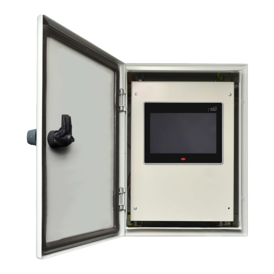
1 fairlead for power supply cable; • the user interface; 2 fairleads for serial connection; • Wall-mounting brackets for Multichiller-Evo metal box; 1 fairlead for pCOe power supply; • • Expansion module formed by a plastic electric box (for wall-mounting) 3 probe sumps;... -
Page 9: Structure Of The Menus
CLOCK control and command board) It allows you to view the state of inputs and outputs of the Multichiller-Evo control board, and it also allows you to: set the connection via BMS, set the thresholds and timings in the INSTALLER... -
Page 10: Interacting With The Graphic Interface
INTERACTING WITH THE GRAPHIC INTERFACE The command and control interface of the unit is based on a touch-screen. to all possible operations, such as the selection of a window, the switching The interface is designed to be used in a simple and intuitive manner; the between windows or the entering of a precise numeric value;... -
Page 11: Modifying The Value Of A Parameter
MODIFYING THE VALUE OF A PARAMETER Many parameters require for the user to enter a numeric value or choose a Select a value from the drop-down list: certain value from a list. The masks that provide settable elements are made of a label that identifies the function of the value to be set and an area (iden- tifiable by the differently coloured background) where to enter the value to be assigned. -
Page 12: System Layout Menu
Current temperature value read by the NTC probe connected on the pCOe board input B2 Chiller ON Each image displays one of the units currently controlled by the MULTICHILLER-EVO accessory. The water value produced from the system side (white) and recovery unit side (red, only on multipurpo-... -
Page 13: System Layout - Chiller Main Monitor - Chiller Sub-Menu - General Status
SYSTEM LAYOUT - Chiller main monitor - CHILLER sub-menu - General status ACTIONS AVAILABLE: Go back to System layout menu; Go to next page Go to alarms menu; Index Meaning Indicates the current Chiller to which the displayed data refers Indicates the family to which the displayed Chiller belongs Indicates the current state of the selected chiller;... -
Page 14: System Layout - Chiller Main Monitor - Chiller Sub-Menu - Alarm Status On Selected Chiller
Each press allows you to enable or disable the chiller control (identified by its index) by the Multichiller-Evo. If this parameter is set at OFF, the chiller cannot in any way be switched on by the Multichiller-Evo (however, the probes would... -
Page 15: On/Off Menu
Set the value of the cold secondary set current setting; this source can be: by touch = settings have been entered through touch panel on the Multichiller-Evo; by digital input = settings have been piloted through digital input ID1; Set the value of the heat secondary set by BMS = settings have been transmitted by BMS;... -
Page 16: On/Off - Main Functioning Settings - Time Periods Sub-Menu - Daily Setting
ON/OFF - Main functioning settings - TIME PERIODS sub-menu - Daily setting ACTIONS AVAILABLE: Go back to the On/Off menu; Go to next page; Go to alarms menu; Select the day of the week to be set; Set the start time (divided by hours and minutes) of the first time period;... -
Page 17: On/Off - Main Functioning Settings - Time Periods Sub-Menu - Copy Hourly Programs Function
Set the system side management (OFF, ON, SET2, CLOCK) Set the value of the recovery side set Set the value of the recovery side secondary Index Meaning Set the value of the differential Indicates the actual status of the Multichiller-Evo... -
Page 18: On/Off - Main Functioning Settings - Time Periods Sub-Menu - Recovery Side Daily Setting (If Multipurpose Units Are Present)
ON/OFF - Main functioning settings - TIME PERIODS sub-menu - Recovery side daily setting (if multipurpose units are present) ACTIONS AVAILABLE: Go back to the On/Off menu; Go to next page; Go to alarms menu; Select the day of the week to be set; Set the start time (divided by hours and minutes) of the first time period;... -
Page 19: On/Off - Main Functioning Settings - Time Periods Sub-Menu - Copy Hourly Programs Function On Recovery Side (If Multipurpose Units Are Present)
ON/OFF - Main functioning settings - TIME PERIODS sub-menu - Copy hourly programs function on recovery side (if multipurpose units are present) ACTIONS AVAILABLE: Go back to the On/Off menu; Go back to previous page; Go to alarms menu; Select the day of the week from which to copy the hourly program;... -
Page 20: Charts Menu
CHARTS MENU With the CHARTS menu you can view the real-time chart of the probes connected to the pCOe expansion board (which must be connected on the system flow and return); CHARTS - Displays real-time charts of the values read by the system side probes ACTIONS AVAILABLE: Open the menu selecting page;... -
Page 21: Language Menu
LANGUAGE MENU With the LANGUAGE menu you can select the system interface lan- guage; LANGUAGE - Selection of system language ACTIONS AVAILABLE: Open the menu selecting page; Go to alarms menu; Allows selecting the English language; Allows selecting the Italian language; Index Meaning Indicates the actual language set on the system... -
Page 22: Installer Menu
INSTALLER MENU Attention: for software versions prior to version "1.2.0", With the INSTALLER menu you can access many of the settings avai- lable for the functioning and adjustment of the system; however, this the password is: 0442 menu may contain parameters whose modification is recommended only to the unit or system maintenance and/or after-sales assistance personnel, which is why the menu requires an access password. -
Page 23: Installer - Inputs/Outputs - Status Of Pco5+ Analogue Inputs
Meaning Current temperature value detected by the NTC probe connected to analogue input U1 on the Multichiller-Evo board. This probe must be installed outdoors in case of Air/water chiller or on the source return in case of Water/Water chiller Indicates the value (the size of which must be set in the “remote control” menu window) read on the system side multifunction input Indicates the value (the size of which must be set in the “remote control”... -
Page 24: Installer - Inputs/Outputs - Status Of Pco5+ Digital Outputs
INSTALLER - Inputs/Outputs - Status of pCO5+ digital outputs ACTIONS AVAILABLE: Go back to the submenu selecting page; Go back to previous page; Go to next page; Go to alarms menu; Index Meaning Indicates the status of digital output NO1 (grey = off; green = on); this output indicates the presence of an active alarm on the system Not used Not used... -
Page 25: Installer - Inputs/Outputs - Status Of Pcoe Analogue Inputs
INSTALLER - Inputs/Outputs - Status of pCOe analogue inputs ACTIONS AVAILABLE: Go back to the submenu selecting page; Go to next page; Go to alarms menu; Go to alarms menu; Index Meaning Actual temperature value detected by the NTC probe connected to analogue input B1 on the pCOe expansion board;... -
Page 26: Installer - Inputs/Outputs - Status Of Pcoe Digital Outputs
INSTALLER - Inputs/Outputs - Status of pCOe digital outputs ACTIONS AVAILABLE: Go back to the submenu selecting page; Go to next page; Go to alarms menu; Go to alarms menu; Index Meaning Not used Not used Not used Not used INSTALLER - Inputs/Outputs - Status of pCOe analogue outputs ACTIONS AVAILABLE:... -
Page 27: Installer - Thresholds And Timings - Chiller On/Off Management
“NO” in the All chillers on = when the Multichiller-Evo gives the On command, all system chillers will be set to Last chiller always ON field (recovery side);... -
Page 28: Installer - Thresholds And Timing - Fixed Threshold Logic Settings
Set the interval between switch-offs with the di- on “Partialisation OFF %” to enable the switch-off command of an additional chiller; If all chillers are forced to Off by the direct command on the Multichiller-Evo (page 14), the switch- rect command from Multichiller-Evo;... -
Page 29: Installer - Thresholds And Timing - Chiller Ignition Priority/Order Settings For Fixed Threshold Management
INSTALLER - Thresholds and timing - Chiller ignition Priority/Order settings for fixed threshold management ACTIONS AVAILABLE: Go back to the submenu selecting page; Go back to previous page; Go to next page; Go to alarms menu; Set the cooling priority of the chillers; Set the cooling heating priority of the chillers;... -
Page 30: Installer - Remote Control - Connection With Bms Settings
Indicates the address associated with the AER485P1 board (not supplied) connected to the parity with the BMS; Multichiller-Evo pCO5+ board to communicate with an external BMS system; Indicates the type of protocol used to communicate with the BMS system; this protocol can be: CAREL = Carel property protocol;... -
Page 31: Installer - Remote Control - Enable On/Off From Digital Input
INSTALLER - Remote control - Enable On/Off from digital input ACTIONS AVAILABLE: Go back to the submenu selecting page; Go back to previous page; Go to next page; Go to alarms menu; Allows enabling or disabling the ID2 digital input; Allows enabling or disabling the ID3 digital input;... -
Page 32: Installer - Remote Control - Multi-Function Input Management
INSTALLER - Remote control - Multi-function input management ACTIONS AVAILABLE: Go back to the submenu selecting page; Go back to previous page; Go to next page; Go to alarms menu; Allows selecting the function to be assigned to the system’s multi-function input; Allows selecting the type of signal applied to the system’s multi-function input;... -
Page 33: Installer - Remote Control - Climatic Curve Settings (U2 Set As Ntc For Outdoor Air Probe)
INSTALLER - Remote control - Climatic curve settings (U2 set as NTC for outdoor air probe) ACTIONS AVAILABLE: Go back to the submenu selecting page; Go back to previous page; Go to next page; Go to alarms menu; Allows setting at which outdoor air temperature to use the primary cooling set;... -
Page 34: Installer - Remote Control - Power Demand/Limitation Settings (U2 Set As Ntc Probe)
INSTALLER - Remote control - Power demand/limitation settings (U2 set as NTC probe) ACTIONS AVAILABLE: Go back to the submenu selecting page; Go back to previous page; Go to next page; Go to alarms menu; Allows setting up to which temperature no chiller will be activated (cooling);... -
Page 35: Installer - Remote Control - Recovery Side Set Point Compensation Settings
INSTALLER - Remote control - Recovery side set point compensation settings ACTIONS AVAILABLE: Go back to the submenu selecting page; Go back to previous page; Go to next page; Go to alarms menu; Allows setting at which outdoor air temperature to use the primary recovery side set;... -
Page 36: Installer - Password - Password Setting
INSTALLER - Password - Password setting ACTIONS AVAILABLE: Go back to the submenu selecting page; Go to alarms menu; Allows setting the value to be assigned to the password to access the installer menu; Index Meaning Indicates the value to be used as password to access the installer menu ATTENTION: Please make a note of any password change in order to avoid possible forgetfulness;... -
Page 37: Installer - Charts - Temperature Probe Setting For Charts Values
However, if a chiller is added at a later stage, the overall management needs to be “fixed threshold” since, in order to use the optimised managements, it is necessary to load the specific data of the units on the Multichiller-Evo (for more information, contact the after-sales service/assistance) -
Page 38: Installer - Chillers Network - Set Of The Connected Chillers
“fixed threshold” since, in order to use the optimised managements, it is Allows specifying whether a pCOe expansion bo- necessary to load the specific data of the units on the Multichiller-Evo (for more information, contact ard is present;... -
Page 39: Installer - Displays - Enables Probe Reading For Nrl/Nrp
INSTALLER - Displays - Enables probe reading for NRL/NRP ACTIONS AVAILABLE: Go back to the submenu selecting page; Go back to previous page; Go to next page; Go to alarms menu; Allows enabling the display of the DK chiller pro- bes;... -
Page 40: Installer - Displays - Enables Debug Menu
INSTALLER - Displays - Enables debug menu ACTIONS AVAILABLE: Go back to the submenu selecting page; Go back to previous page; Go to alarms menu; Allows enabling the display of the debug menu; Enables display of the system’s differential for WRL units;... -
Page 41: Manufacturer Menu
MANUFACTURER MENU The MANUFACTURER menu contains confidential settings, the modifi- cation of which is not available to the user or installer; the parameters contained in this menu are only available to the company’s technical after-sales service/assistance; MANUFACTURER - Access password entering ACTIONS AVAILABLE: Allows entering the numeric value of the pas-... -
Page 42: Alarms Menu
ALARMS MENU With the ALARMS menu you can view, and possibly reset, the alarm before performing the reset, you must be sure of the nature of the conditions arisen in the unit during its functioning; the alarms are di- alarm and its cause (possibly by referring to the specific after-sales as- vided into different categories according to their severity. -
Page 43: Multichiller-Evo List Of Alarms
Multichiller-Evo list of alarms Index Meaning Index Meaning AL001 U1 broken or disconnected AL037 Slave1 Chiller3 offline AL002 U2 broken or disconnected AL038 Slave2 Chiller3 offline AL003 U3 broken or disconnected AL039 Slave3 Chiller3 offline U4 broken or disconnected Slave1 Chiller4 offline... - Page 44 Tel. (+39) 0442 633111 Telefax 0442 93577–(+39) 0442 93566 www.aermec.com - [email protected] The technical data given on the following documentation are not binding. Aermec reserves the right to make at any time all the modifications deemed necessary for improving the product.