
Related Manuals for Honeywell NOTIFIER APS2-6R/E


Summary of Contents for Honeywell NOTIFIER APS2-6R/E
- Page 1 Auxiliary Power Supply APS2-6R/E Instruction Manual Document 53232 2/26/2014 Rev: P/N 53232:B ECN 14-0161...
- Page 2 Fire Alarm & Emergency Communication System Limitations While a life safety system may lower insurance rates, it is not a substitute for life and property insurance! An automatic fire alarm system—typically made up of smoke (caused by escaping gas, improper storage of flammable materi- detectors, heat detectors, manual pull stations, audible warning als, etc.).
- Page 3 HARSH™, NIS™, and NOTI•FIRE•NET™ are all trademarks; and Acclimate® Plus, FlashScan®, NION®, NOTIFIER®, ONYX®, ONYXWorks®, UniNet®, VeriFire®, and VIEW® are all registered trademarks of Honeywell International Inc. Echelon® is a registered trademark and LonWorks™ is a trademark of Echelon Corporation. ARCNET® is a registered trademark of Datapoint Corporation. Microsoft® and Windows® are registered trademarks of the Microsoft Corporation.
- Page 4 •Brief description of content you think should be improved or corrected •Your suggestion for how to correct/improve documentation Send email messages to: [email protected] Please note this email address is for documentation feedback only. If you have any technical issues, please contact Technical Services.
-
Page 5: Table Of Contents
Table of Contents Section 1: Introduction......................6 1.1: Installation Standards and Codes........................6 1.2: UL 864 9th Edition Compliance........................6 1.3: Compatible Equipment ..........................6 1.4: Related Documentation ..........................6 1.5: Cautions, Warnings, and Notes........................7 Section 2: Overview........................8 2.1: Description..............................8 2.2: Features................................8 2.3: Specifications..............................9 2.4: Board Layout ...............................10 Section 3: Installation ...................... -
Page 6: Section 1: Introduction
Section 1: Introduction This document contains information for installing, servicing, and configuring the APS2-6R Auxiliary Power Supply. Section 1.4 lists part numbers for manuals of compatible equipment such as control panels. 1.1 Installation Standards and Codes This power supply complies with the standards set forth by the following regulatory agencies: NFPA Standards •... -
Page 7: Cautions, Warnings, And Notes
Cautions, Warnings, and Notes Introduction Document Name Part Number RM-1 Remote Microphone Installation Document 51138 OnyxWorks NFN Gateway (PC Platform) 52307 OnyxWorks NFN Gateway (Embedded Platform) 52306 BACNet Gateway 51659 HS-NCM Series Installation Document 54014 Notifier Device Compatibility Document 15378 1.5 Cautions, Warnings, and Notes This manual contains cautions, warnings, and notes to alert the reader as follows: CAUTION:Information about procedures that could cause programming errors,... -
Page 8: Section 2: Overview
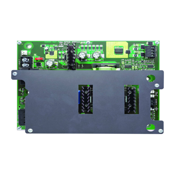
Section 2: Overview 2.1 Description The APS2-6R Auxiliary Power Supply is a 150W cabinet-mounted power supply, designed to power devices that require filtered, non-resettable power. The APS2-6R provides three 24 VDC (filtered) output circuits. Figure 2.1 APS2-6R Auxiliary Power Supply NOTE: Unless otherwise indicated in this manual, the name APS2-6R refers to both the APS2-6R and APS2-6RE. -
Page 9: Specifications
Specifications Overview 2.3 Specifications AC Power - TB1 APS2-6R - 120VAC, 50/60 Hz, 2.9A max APS2-6RE - 220-240 VAC, 50/60 Hz, 1.5A max Earth Ground - Connects to chassis or earth ground terminal on main power supply. If two units are connected, the second unit connects to earth ground on the previous AP2S-6R in the chain. -
Page 10: Board Layout
Overview Board Layout Removal of the shunt from JP4 separates the AC loss trouble from other existing troubles and works with the TB4 relay contacts for immediate trouble annunciation. Diagnostic LEDs LED1- Green- Indicates presence of AC power LED2- Yellow- Illuminates when an AC or battery trouble exists 2.4 Board Layout The figures below identify the layout of the APS2-6R power supply: NOTE: The cover has been... -
Page 11: Section 3: Installation
Section 3: Installation WARNING: HIGH VOLTAGES PRESENT Use extreme caution when working with the APS2-6R. High voltage and AC line-connected circuits are present. Turn off and remove all power sources. To reduce the risk of electric shock make sure to properly ground the unit. Be sure to apply and test AC power before connecting batteries. -
Page 12: 2: In An Afp-200 Cabinet
Installation UL Power-limited Wiring Requirements 6. Reinstall the AFP-200 CPU board assembly. APS2-6R Screws mounting holes (2 places) battery connection AFP-200 Cabinet Figure 3.2 Mounting an APS2-6R into an AFP-200 Cabinet 3.2 UL Power-limited Wiring Requirements Power-limited wiring must remain separated from non-power-limited wiring by at least 0.25 in. (6.4 mm), and must enter the enclosure through different knockouts. -
Page 13: 2: Ac Fail/Brownout Detection
Wiring an APS2-6R Installation 3.3.2 AC Fail/Brownout Detection The APS2-6R monitors for power loss. In the event there is an AC failure or brownout, the APS2-6R will switch to battery back-up. The AC Fail Relay (TB4) is monitored by an FMM-1 or equivalent monitor module on the SLC (Signaling Line Circuit), and in this event, a trouble message will be displayed on the control panel. -
Page 14: 4: Connecting Multiple Aps2-6R Power Supplies
Installation Configuring the APS2-6R 3.3.4 Connecting Multiple APS2-6R Power Supplies The power supplies must be mounted in a CHS-4/L chassis oriented as shown in Figure 3.5 to accommodate all field wiring. Cable #71033 must be used for all trouble bus connections. For more information on specific panel wiring, see the appropriate appendix. -
Page 15: Servicing The Aps2-6R
Servicing the APS2-6R Installation 3.5 Servicing the APS2-6R The only serviceable part on the APS2-6R is a reverse battery protection fuse, F2. If this fuse fails, replace it with a fuse of the same type and rating. See Section 2.3 for more information on F2. 1. - Page 16 Notes APS2-6R/E Instruction Manual — P/N 53232:B 2/26/2014...
-
Page 17: Appendix A: Ul 864 9Th Edition Configurations
Appendix A: UL 864 9th Edition Configurations The APS2-6R does not come equipped with a battery charger. Therefore, it must be connected to the control panel’s main power supply. This section details wiring for UL 864 9th Edition applications. All wiring must comply with typical UL power-limited wiring requirements detailed in Section 3.2 and illustrated in Figure A.1. - Page 18 UL 864 9th Edition Configurations NFS2-3030 Note: Maintain 0.25” spacing between Power-limited and Non-power-limited wiring. Install tie wraps and adhesive squares to secure the wiring. side view FMM-1* Power- Power- NFS2-3030 Limited Limited Circuits Circuits Non-Power- Limited Circuits Non-Power- TBL BUS MAIN 24 TBL AUX24 TBL MAIN 24...
-
Page 19: A.2: Nfs2-640 And Nfs-320
NFS2-640 and NFS-320 UL 864 9th Edition Configurations A.2 NFS2-640 and NFS-320 The APS2-6R must be mounted to the CHS-4/L chassis in the CAB-3/4 Series backbox. See “In a CAB-3/4 Series Backbox” on page 11. A.2.1 Connecting to the CPS-24 and CPU2-640/NFS-320 1. -
Page 20: Appendix B: Ul 864 8Th Edition Configurations
Appendix B: UL 864 8th Edition Configurations The APS2-6R does not come equipped with a battery charger. Therefore, it must be connected to the control panel’s main power supply. This section details wiring for UL 864 8th Edition applications. All wiring must comply with typical UL power-limited wiring requirements detailed in Section 3.2 and illustrated in Figure A.1. -
Page 21: B.2: Afp-300/Afp-400
AFP-300/AFP-400 UL 864 8th Edition Configurations 7. Attach battery interconnect cable. Note: Maintain 0.25” spacing between Power-limited and Non-power-limited wiring. Install tie wraps and adhesive Power-limited circuit squares to secure the wiring. grounding stud Non-power-limited circuits The shaded area and dotted lines represent the APS2-6R and wiring behind the panel. -
Page 22: B.3: Am2020/Afp-1010 And System 5000
UL 864 8th Edition Configurations AM2020/AFP-1010 and System 5000 7. Attach battery interconnect cable. Note: Maintain 0.25” spacing between Power- limited and Non-power-limited wiring. Install tie wraps and adhesive squares to secure the wiring. MPS-400 Non-power-limited Power-limited to battery + back-up - APS2-6R Non-power-limited... -
Page 23: B.3.2: Connecting To An Mps-24B/Rb
AM2020/AFP-1010 and System 5000 UL 864 8th Edition Configurations 7. Attach battery interconnect cable. Note: Maintain 0.25” spacing between Power-limited and Non-power-limited wiring. Install tie wraps and adhesive squares to secure the wiring. POWER LIMITED BAT + BAT - +24R COMMON COMMON EARTH GND... -
Page 24: B.4: Nfs-640
UL 864 8th Edition Configurations NFS-640 7. Attach battery interconnect cable. Note: Maintain 0.25” spacing between Power-limited and Non-power-limited wiring. Install tie wraps and adhesive squares to secure the wiring. MPS-24B Power-limited Non-power-limited to battery + back-up - APS2-6R Non-power-limited Figure B.4 Wiring to MPS-24B B.4 NFS-640 The APS2-6R must be mounted to the CHS-4/L chassis in the CAB-3/4 Series backbox. -
Page 25: B.5: Nfs-3030
NFS-3030 UL 864 8th Edition Configurations 7. Attach battery interconnect cable. Note: Maintain 0.25” spacing between Power-limited and Non-power-limited wiring. Install tie wraps and adhesive squares to secure the wiring. Power-limited CPU-640 Non-power-limited Power-limited to battery + back-up - Non-power-limited APS2-6R Figure B.5 Wiring to CPU-640 B.5 NFS-3030... -
Page 26: B.6: Xpiq Transponder
UL 864 8th Edition Configurations XPIQ Transponder 7. Attach battery interconnect cable. Note: Maintain 0.25” spacing between Power-limited and Non-power-limited wiring. Install tie wraps and adhesive squares to secure the wiring. Power-limited Non-power-limited APS2-6R to battery + CPU-3030 back-up - Non-power-limited AMPS-24 Figure B.6 Wiring to AMPS-24 and CPU-3030... -
Page 27: B.7: Panel Circuits
Panel Circuits UL 864 8th Edition Configurations 8. Attach battery interconnect cable. Spkr4 Note: Maintain 0.25” spacing between Power-limited and Non-power-limited TRBL SPKR4 Riser TRBL wiring. Install tie wraps and adhesive Phone 1 Phone1 TRBL PHONE squares to secure the wiring. 1 AND 2 Phone 2 2 X 2W... - Page 28 Notes APS2-6R/E Instruction Manual — P/N 53232:B 2/26/2014...
-
Page 29: Index
Index FMM-1 13 fuse 9 AC loss detection 13 AC loss detection, delay 8 AC power 9 ACS annunciators 6 hardware kit 10 AFP-200 6 HS-NCM Series 7 battery cable 20 AFP-200 cabinet 11 AFP-300 21 ICE-4 27 AFP-300/AFP-400 6 ICM-4 27 AFP-400 21 IPDACT Internet Protocol DACT 6... - Page 30 R–X Index power connections 12 power-limited circuit 10 primary power 17 related documentation 6 replacing fuse 15 RM-1 Remote Microphone 7 secondary power 17 shunt 20 SLC 13 specifications 9 output circuits 9 primary power 9 secondary power circuit 9 status indicators 10 System 5000 6 trouble bus 8...
- Page 31 Manufacturer Warranties and Limitation of Liability Manufacturer Warranties. Subject to the limitations set forth herein, Manufacturer warrants that the Products manufactured by it in its Northford, Connecticut facility and sold by it to its authorized Distributors shall be free, under normal use and service, from defects in material and workmanship for a period of thirty six months (36) months from the date of manufacture (effective Jan.
- Page 32 World Headquarters 12 Clintonville Road Northford, CT 06472-1610 USA 203-484-7161 fax 203-484-7118 www.notifier.com...