
Related Manuals for ABB F Series


Summary of Contents for ABB F Series
- Page 1 — OPTIONS FOR ABB DRIVES AND CONVERTERS FEA-03 F-series extension adapter User's manual...
- Page 3 FEA-03 F-series extension adapter User's manual Table of contents 1. Safety instructions 4. Mechanical installation 5. Electrical installation 3AUA0000115811 Rev C Original instructions EFFECTIVE: 2021-10-04...
-
Page 5: Table Of Contents
Table of contents 5 Table of contents 1 Safety instructions Contents of this chapter ................Use of warnings and notes ............... General safety instructions ............... 2 Introduction to the manual Contents of this chapter ................Applicability ..................Compatibility ..................Target audience ..................Purpose of the manual ................ - Page 6 6 Table of contents 8 Technical data Housing ....................Mounting .................... Power supply connection ................. Connectors ..................L E D ....................Ambient conditions ................Degree of protection ................Standards ................... Dimensions ..................Further information...
-
Page 7: Safety Instructions
Safety instructions 7 Safety instructions Contents of this chapter This chapter contains the safety instructions which you must obey when you install and operate the drive and do maintenance on the adapter. If you ignore the safety instructions, injury, death or damage can occur. In addition to these safety instructions, read the complete safety instructions of the specific drive you are working on. -
Page 8: General Safety Instructions
8 Safety instructions General safety instructions These warnings are intended for all who work on the drive, motor cable or motor. WARNING! Obey these instructions. If you ignore them, injury or death, or damage to the equipment can occur. • If you are not a qualified electrician, do not do grounding work. •... -
Page 9: Introduction To The Manual
Introduction to the manual 9 Introduction to the manual Contents of this chapter This chapter introduces this manual. Applicability This manual applies to the FEA-03 F-series extension adapter. Compatibility The FEA-03 F-series extension adapter is compatible with FIO-01, FIO-11, FAIO-01, FDIO-01, FEN-01, FEN-11, FEN-21 and FEN-31 option modules only. -
Page 10: Before You Start
FDCO-01/02 DDCS communication modules user's 3AUA0000114058 guide RDCO-01/02/03/04 DDCS Communication option 3AFE64492209 modules Manuals and quick guides for I/O extension modules, fieldbus adapters, etc. You can find manuals and other product documents in PDF format on the Internet at www.abb.com/drives/documents. -
Page 11: Hardware Description
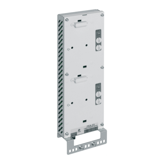
Hardware description 11 Hardware description Contents of this chapter This chapter contains a short description of the FEA-03 F-series extension adapter and the optical component types. Overview The FEA-03 is an extension adapter that is used to install I/O extension modules and encoder interface modules outside the drive unit. - Page 12 12 Hardware description Slot 1 Slot 2 Module connector 1 Status LED for Slot 1 Node address switch A Node address switch B Module connector 2 Status LED for Slot 2 Node address switch C Node address switch D Power supply connector (XPOW) Transmitter V1T and receiver V1R Transmitter current selector You can connect several FEA-03 extension adapters in a ring topology with a fibre-optic...
-
Page 13: Optical Component Types
Hardware description 13 Optical component types The FEA-03 F-series extension adapter has a 10 MBd fiber-optic link. The drive must also have a 10 MBd DDCS fiber-optic connection. These optical cable types can be used: • Plastic optical fibre (POF) cables (max. length 30 m [98 ft]) and ®... -
Page 15: Mechanical Installation
Mechanical installation 15 Mechanical installation Contents of this chapter This chapter contains a delivery checklist and instructions on how to install the extension adapter. Examining the delivery The package contains: • FEA-03 F-series extension adapter • fastening screws and latches for DIN rail installation •... -
Page 16: Installing The Adapter Vertically On A Din Rail
16 Mechanical installation Installing the adapter vertically on a DIN rail ■ 1. Attach the support bracket in the correct position on the wall. 2. Attach the latch to the back side of the adapter. 3. Click the adapter to the DIN rail. 4. -
Page 17: Installing The Adapter Horizontally On A Din Rail
Mechanical installation 17 Installing the adapter horizontally on a DIN rail ■ 1. Attach the latches to the back side of the adapter. 2. Click the adapter to the DIN rail. -
Page 18: Installing An Option Module On The Adapter
18 Mechanical installation Installing an option module on the adapter 1. Remove the cover from the module connector. 2. Pull out the lock on the option module. 3. Put the top edge of the option module into its position and push the module carefully into its position until the retaining clips lock it into position. -
Page 19: Removing An Option Module From The Adapter
Mechanical installation 19 Removing an option module from the adapter 1. Remove the screw. 2. Pull out the lock and remove the module. -
Page 21: Electrical Installation
Electrical installation 21 Electrical installation Contents of this chapter This chapter tells how to connect the FEA-03 F-series extension adapter to the drive. Connecting the adapter to the drive control unit Connect the adapter to the drive control unit through a DDCS communication module. With the BCU control unit, you can use an RDCO or FDCO communication module. - Page 22 22 Electrical installation FEA-03 FEA-03 FEA-03 FEA-03 V1T V1R FDCO FDCO RDCO RDCO 1. If you use an FDCO module, set the current selector switch to agree with the cable length as shown in the table below. Switch position Cable length POF, 1 mm HCS, 200 μm 0 - OFF...
-
Page 23: Start-Up
Start-up 23 Start-up Contents of this chapter This chapter contains the start-up instructions for the extension adapter. Defining node IDs for option modules You must define a node ID for each option module connected to the FEA-03 F-series extension adapter. The node ID is a two-digit decimal number that must be unique for each option module connected to the drive. -
Page 25: Diagnostics
Diagnostics 25 Diagnostics Contents of this chapter This chapter explains how to trace faults with the status LEDs on the extension adapter. General See the applicable drive firmware manual for fault and warning messages. Diagnostic LEDs Color Description PWR OK Green Is lit when power applied to the extension adapter is SLOT 1 STATUS... - Page 27 Technical data 27 Technical data Housing Painted and zinc-plated sheet steel. Mounting Onto 35 x 7.5 DIN rail. Power supply connection • Voltage: 24 V DC ±10% • Current consumption: Refer to I/O extension module's User's manual. Connectors • Fiber-optic link connection: Avago Versatile Link (10 MBd) •...
- Page 28 28 Technical data Degree of protection IP20 Standards Complies with the safety standard IEC 61800-5-1 and EMC standard IEC 61800-3. Dimensions...
- Page 29 Product and service inquiries Address any inquiries about the product to your local ABB representative, quoting the type designation and serial number of the unit in question. A listing of ABB sales, support and service contacts can be found by navigating to www.abb.com/searchchannels.
- Page 30 3AUA0000115811C © Copyright 2021 ABB. All rights reserved. Specifications subject to change without notice.