Table of Contents
Quick Links
Instruction Manual
VCIMD-14946
November 2021
Spence Types K5 and K6 Control Valve
▲
Failure to follow these instructions or
to properly install and maintain this
equipment could result in an explosion,
fire and/or chemical contamination
causing property damage and personal
injury or death.
Emerson Control Valve must be
installed, operated and maintained
in accordance with federal, state and
local codes, rules and regulations
and Emerson Process Management
Regulator Technologies, Inc.
(Emerson) instructions.
If the control valve vents gas or a
leak develops in the system, service
to the unit may be required. Failure
to correct trouble could result in a
hazardous condition.
Installation, operation and maintenance
procedures performed by unqualified
personnel may result in improper
adjustment and unsafe operation. Either
condition may result in equipment
damage or personal injury. Only a
qualified person shall install or service
the Types K5 and K6 control valve.
Introduction
Scope of the Manual
This manual provides instructions for the installation,
start-up, setting, maintenance, troubleshooting and
parts ordering for Types K5 and K6 control valve and
Type SKD62U Electric Actuator.
WARNING
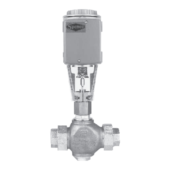
Figure 1. Types K5 and K6 Control Valves
Figure 2. Type SKD62U Electric Actuator.
www.SpenceValve.com
www.SpenceValve.com
Types K5 and K6
Table of Contents

Related Manuals for Emerson Spence K5


Summary of Contents for Emerson Spence K5
- Page 1 Emerson Control Valve must be installed, operated and maintained in accordance with federal, state and local codes, rules and regulations and Emerson Process Management Regulator Technologies, Inc.
-
Page 2: Specifications
Types K5 and K6 Specifications This section lists the specifications for the Types K5 and K6 and Type SKD62U Electric Actuator. Factory specification are stamped on the nameplate fastened on the control valve and actuator at the factory. Types K5 and K6 Control Valves Type SKD62U Electric Actuator (continued) Control Signals Control Valve Types... -
Page 3: Product Description
Types K5 and K6 EA0170R1 TEMPERATURE, °F ANSI/ASME B16.15 CLASS 250 SATURATED STEAM Figure 3. Auxillary Switch Figure 4. Types K5 and K6 Pressure and Temperature Chart Table 1. Types K5 and K6 Approximate Weight VALVE SIZE WEIGHT 17.5 1-1/4 23.5 1-1/2 23.5... -
Page 4: Installation
Types K5 and K6 SPENCE SAFETY RELIEF VALVE SPENCE UNIFLEX UNION SPENCE UNIFLEX UNION SPENCE DRIP PAN ELBOW SPENCE STEAM SPENCE TRAP STEAM TRAP SPENCE K5 AND K6 CONTROL VALVE SPENCE STEAM TRAP Figure 5. Types K5 and K6 Control Valve Recommended Installation for Steam Application Installation △... -
Page 5: Maintenance
Only parts manufactured by Emerson should be used for repairing this Start-up and Setting control valve. Due to normal wear or damage that may ▲... -
Page 6: Packing Replacement
Types K5 and K6 Disassembly of the Valve Body Replacing the Actuator on the Valve Body (See Figures 21 to 24) 1. Remove the stem adapter, stem nuts (key 24) and locking nut. 1. Thread the stem adapter all the way onto the valve stem. - Page 7 Types K5 and K6 ACTUATOR KEY FOR FIGURE 6 SKD620 Use earth ground isolating step-down Class 2 transformer per Siemens SKD62U actuator instructions. 4-20 mA CONTROLLER OPERATING VOLTAGE 24 vAC FOR INPUT SIGNAL 24 VAC System Potential (SP) System Neutral (SN) ANALOG SCALING MODULE ASM1 Control Input 0-10 vDC...
- Page 8 Types K5 and K6 0 to 135 Ohm 1. Remove the electric actuator control box cover and wire electric actuator and analog scaling module according to Figure 6B. 2. Set the signal potentiometer to 135 ohm. 3. Adjust the span potentiometer on the analog scaling module until the total valve travel is within 10% of rated travel.
-
Page 9: Troubleshooting
Control valves that have been actuator adjustment section for Types K5 and K6. disassembled for repair must be tested for proper operation before being returned to service. Only parts manufactured by Emerson should be used for repairing this control valve. -
Page 10: Mounting And Installation
Types K5 and K6 EA0410R1 Figure 10. Acceptable Mounting Positions To troubleshoot the valve and actuator, check for Installation, operation and maintenance procedures performed by unqualified the following: change in operating conditions; signal failure; power failure; foreign matter lodged between personnel may result in improper seat ring and plug;... - Page 11 Types K5 and K6 INDICATOR MANUAL AUTO EA0386R1 Figure 12. The Manual Setting Knob in Manual and Automatic Position G, G0 Operating voltage 24 Vac System Potential (SP) System Neutral (SN) Control input 0 to 10 Vdc Input for 4 to 20 mA or 0 to 1000 Ohm remote setting unit Measuring neutral Output for 0 to 10 Vdc or 4 to 20 mA measuring voltage.
- Page 12 Types K5 and K6 EARTH GROUND ISOLATING CLASS 2 TRANSFORMER FOR 24 VAC POWER MAX 10 DEVICES PER OUTPUT SIGNAL CAUTION: Modules must be in the same field panel. DO NOT EXCEED MAX 100 VA PER TRUNK EARTH GROUND ISOLATING CLASS 2 TRANSFORMER FOR 24 VAC POWER Figure 15.
- Page 13 Types K5 and K6 MAX 10 DEVICES PER AOV MAX 100 VA EARTH GROUND ISOLATING CLASS 2 TRANSFORMER FOR 24 VAC POWER EA0167R2 Figure 17. SCU Wiring Diagram for SEA in Series with 0 to 10 Vdc signal 100 VA EA0185R1 Figure 19.
-
Page 14: Manual Operation
Types K5 and K6 Normally Closed Valve Manual Operation • Actuator pressure cylinder moves outward (0 to 1): 1. Turn the manual setting knob clockwise for manual Valve opens. operation. As you begin to turn, a red indicator becomes visible. Each complete revolution (360°) •... -
Page 15: Service Kits
Types K5 and K6 Table 2. Types K5 and K6 Valve Body Assembly Part Numbers VALVE SIZE PART NAME MATERIAL NPS 1/2 / DN 15 NPS 3/4 / DN 20 NPS 1 / DN 25 NPS 1-1/4 / DN 32 NPS 1-1/2 / DN 40 NPS 2 / DN 50 Stem Nut... - Page 16 Types K5 and K6 Figure 20. Types K5 and K6 Valve Body Assembly - NPS 1/2 and 3/4 / DN 15 and 20...
- Page 17 Types K5 and K6 Figure 21. Type K6 Valve Body Assembly NPS 1 to 2 / DN 25 to 50...
- Page 18 Types K5 and K6 Figure 22. Type K5 Valve Body Assembly - NPS 1 to 2 / DN 25 to 50...
- Page 19 Types K5 and K6 ELECTRIC ACTUATOR 05-17381-00 STEM RETAINER STEM ADAPTER 4-17407-0 LOCKING NUT 4-17338-0 Figure 23. Types K5 and K6 Actuator Assembly...
- Page 20 SpenceValve.com VCIMD-14946 © 2021 Emerson Electric Co. All rights reserved. 11/21 Spence is a mark owned by one of the companies in the Emerson Automation Emerson Automation Solutions Solutions business unit of Emerson Electric Co. The Emerson logo is a trademark and service mark of Emerson Electric Co.