
Related Manuals for Emerson Rosemount 936


Summary of Contents for Emerson Rosemount 936
- Page 1 Reference Manual 00809-0100-4036, Rev AD October 2021 ™ Rosemount Toxic Open Path Gas Detector...
- Page 2 No part of the hardware, software, or documentation may be reproduced, transmitted, transcribed, stored in a retrieval system, or translated into any language or computer language in any form or by any means without prior written permission of Emerson. While great efforts have been made to ensure the accuracy and clarity of this document, Emerson assumes no responsibility resulting from any omissions in this document or from misuse of the information obtained herein.
- Page 3 Abbreviation Meaning Light-emitting diode Liquified natural gas MilliAmps (0.001 amps) ® Modbus Master-slave messaging structure Not applicable National pipe thread NTSC National Television System Committee (a color encoding system) Phase alternation by line (a color encoding system) Part number Concentration in parts per million. Defines the amount of gas molecule parts per million molecules of atmospheric ppm.m Integral of concentration in ppm units times the distance in meters.
-
Page 5: Table Of Contents
5.8 Wiring to detector terminals......................45 5.9 Wiring to ultraviolet (UV) source....................45 5.10 Align detector..........................47 Chapter 6 Operation........................ 51 6.1 Operating the open path system....................51 6.2 Safety precautions........................51 6.3 Power up........................... 51 6.4 Verifying signal.......................... 52 6.5 Zero calibrate..........................54 Rosemount 936... - Page 6 A.1 RS-485 communication network....................67 Appendix B SIL-2 features......................69 B.1 Safety relevant parameters......................69 B.2 General conditions for safe use....................69 Appendix C Support........................71 C.1 Return of material........................71 Appendix D Short range model....................73 Appendix E Declaration of Conformity..................75 Emerson.com/Rosemount...
-
Page 7: Chapter 1 Product Overview
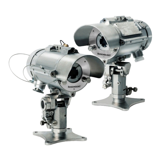
October 2021 Product overview The Rosemount 936 Gas Detector employs an advanced xenon flash source and integrated electronics package, both housed in stainless steel housings to provide high quality and performance, fast response, and line of sight gas monitoring. The source/ detector is backed by a three year warranty. - Page 8 Product overview Reference Manual October 2021 00809-0100-4036 Emerson.com/Rosemount...
-
Page 9: Chapter 2 Technical Description
Class I Zone 1 AEx db eb ib [ib Gb] IIB+H T4 Gb Zone 21 AEx tbm [ib Db] IIC T135 °C Db = -55 °C to +65 °C • TUV approved per SIL2 requirements. • Inmetro (UL) approved. • Programmable configuration via the Field Communicator Rosemount 936... -
Page 10: Applications
2.3.2 Optical path The Rosemount 936 detects the presence of toxic airborne vapors, gases, or aerosols in a monitored area when the defined substance crosses/enters the optical path between the radiation source unit and the detector. - Page 11 189 nm to 270 nm, which enables fast and reliable detection at low concentrations. 2.3.4 Ultraviolet (UV) source The Rosemount 936 employs the latest generation of Xenon UV flash bulbs to provide extended installation distance and maximum reliability. 2.3.5 Heated optics The Rosemount 936 includes heated optics for the detector and source.
-
Page 12: Product Certifications
• Display health and status You can connect the HART communication on the 0-20 mA line or thought the intrinsically safe (I.S.) connection with a standard Field Communicator loaded with Emerson's host software and attached by a special harness. ®... - Page 13 2.4.4 INMETRO The Rosemount 936 is in compliance with the standards ABNT NBR IEC 60079-0, ABNT NBR IEC 60079-1, ABNT NBR IEC 60079-7, ABNT NBR IEC 60079-11, ABNT NBR IEC 60079-28, ABNT NBR IEC 60079-31, and INMETRO decree No. 179 as of May 18th, 2010.
-
Page 14: Models And Types
Reference Manual October 2021 00809-0100-4036 The Rosemount 936 is a "Class 1 Laser Product" per IEC 60825-1: 2014 ed. 05. Models and types The Rosemount 936 is available as three transmitter models, determining the detection distance, with two possible detectors, detecting H S or ammonia. - Page 15 Transmitter - Range of 46 to 132 ft (14 to 40 m) Transmitter - Range of 115 to 200 ft (35 to 60 m) Gas calibration Code Description Transmitter Housing style / conduit Code Material Measurement Stainless steel ¾-in NPT Stainless steel Product certifications Code Description ATEX and IECEx Rosemount 936...
- Page 16 Toxic Open Path Gas Detector (Receiver) Receiver selection Code Description Receiver Gas calibration Code Description Hydrogen sulfide (receiver) Ammonia (receiver) Housing style / conduit Code Material Measurement Stainless steel ¾-in NPT Stainless steel Product certifications Code Description ATEX and IECEx INMETRO CU TR (EAC) Emerson.com/Rosemount...
-
Page 17: Description
• Ultraviolet source • Detector The Rosemount 936 detects gases over an open path transmitted from the source to the detector. 2.7.1 Ultraviolet (UV) source unit The UV source unit emits radiation pulses at the rate of one pulse per second. - Page 18 A. Front window B. Handheld fast connection C. Weather shield D. Front window section E. Label F. Main housing G. Mounting plate H. Junction box I. Back cover J. Indicator light-emitting diode (LED) K. Earth terminal L. Cable inlet Emerson.com/Rosemount...
-
Page 19: Chapter 3 Operating Modes
Reference Manual Operating modes 00809-0100-4036 October 2021 Operating modes Operational modes The Rosemount 936 has four operational modes: • Normal mode • Maintenance call mode (3 mA output) • Fault mode • Zero calibration mode (1 mA output) 3.1.1 Normal mode This mode is used for gas detection. -
Page 20: Visual Indicators
Fault Yellow 4 Hz - flashing Alignment / Standby Yellow 1 Hz - flashing Zero calibration Yellow Constant Normal Green 1 Hz - flashing Warning 2 Hz - flashing Alarm Constant The source statuses are listed in Table 3-2. Emerson.com/Rosemount... -
Page 21: Output Signals
Fault Yellow 4 Hz - flashing Normal Green 1 Hz - flashing Output signals The Rosemount 936 system provides the following outputs: • 0-20 mA current output • RS-485 interface 3.3.1 0-20 mA current output The 0-20 mA output provides the detector status measurements showing a continuous reading of exact gas concentration. -
Page 22: System Setup
Reference Manual October 2021 00809-0100-4036 System setup 3.4.1 Program detection functions The Rosemount 936 incorporates several functions that can be set by the customer using: • WinHost software ® • HART Field Communicator: The detector is equipped with an intrinsically safe connector to enable HART communication. - Page 23 Reference Manual Operating modes 00809-0100-4036 October 2021 Table 3-4: Detector Default Setup Function Setup Heat mode Auto Heat on 41 °F (5 °C) You can change the source defaults the same way. Rosemount 936...
- Page 24 Operating modes Reference Manual October 2021 00809-0100-4036 Emerson.com/Rosemount...
-
Page 25: Chapter 4 Specifications
< 3 sec, < 10 sec to T90 Spectral response 200 to 300 nm Sensitivity range Full scale Warning Alarm 500 ppm/m 100 ppm/m 300 ppm/m Field of view Line of sight Alignment tolerance ±1 degree Minimum detectable gas volume 50 ppm/m Rosemount 936... -
Page 26: Electrical Specifications
A digital communication protocol used to communicate between intelligent field instruments and the host system. Through the HART protocol, the detector can: — Display setup. — Reconfigure setup. — Display and determine the detector status. — Perform detector diagnostics. Emerson.com/Rosemount... -
Page 27: Mechanical Specifications
Source: 10.5 x 5.1 x 5.1 in. (267 x 130 x 130 mm) • Tilt mount: 4.7 x 4.7 x 5.5 in. (120 x 120 x 140 mm) Weight Detector: 11 lb. (5 kg) Source: 11 lb. (5 kg) Tilt mount: 4.2 lb. (1.9 kg) Rosemount 936... -
Page 28: Environmental Specifications
Reference Manual October 2021 00809-0100-4036 Environmental specifications The Rosemount 936 system is designed to withstand harsh environmental conditions. The source and detector units compensate for adverse conditions while maintaining accuracy. High temperature The Rosemount 936 is designed to meet DNVGL-CG-0039, class D. - Page 29 To fully comply with EMC directive 2014/30/EU and protect against interference caused by radio frequency interference (RFI) and electromagnetic interference (EMI), the cable to the detector must be shielded, and the detector must be grounded. Ground the shield at the detector end. Rosemount 936...
- Page 30 Specifications Reference Manual October 2021 00809-0100-4036 Emerson.com/Rosemount...
-
Page 31: Chapter 5 Installation
Mounts the detector on the tilt mount. Hex key 3/16 in. Aligns the detector. Screws ¾ stop plug. Hex key 5/16 in. Flat screwdriver 4 mm Connects ground terminal. Flat screwdriver 2.5 mm Connects wires to the terminal block. Rosemount 936... - Page 32 5.2.3 Site requirements When installing the Rosemount 936, take into account the weight of the monitored gas compared to that of the surrounding air and the individual site requirements. Ensure that the site selected gives the detector a direct view to the source. The mounting point for each item should be secure and stable with minimal vibrations.
- Page 33 To fully comply with electromagnetic compatibility (EMC) directive and protect against interference caused by radio frequency interference (RFI) and electromagnetic interference (EMI), the cable to the detector must be shielded, and the detector must be grounded. Ground the shield at the detector end. Rosemount 936...
-
Page 34: Preparations For Installation
Handle for cover opening • Alignment tool kit • Function check filter: for H S or NH Other accessories are available, per customer request: • Pole mount (U-bolt 5 in.) • Pole mount (U-bolt 2-3 in.) • RS-485 harness kit Emerson.com/Rosemount... -
Page 35: Certification Instructions
• HART hand-held harness kit • Protective cover See the Rosemount 936 Product Data Sheet for the accessory part numbers. 5.3.2 Unpacking Upon receipt of your detector, check and record the following: • Verify the appropriate purchase order. Record the part number and the serial number of the detectors and source units and the installation date in the appropriate log book. - Page 36 7.5 mH 7.5 mH 514 µH 96.9 µH Note Co @ 6.6 V is 22 µF, as per Table A.2 of IEC 60079-11:2011. Lo is calculated based on 1.5 times current for IIC, 40 µJ using E = 0.5 *(LI) Emerson.com/Rosemount...
- Page 37 CSA 80023016 Conditions for Canadian installations 1. The dimensions of the flameproof joints are other than the relevant minimum or maximum values required by Table 2 of CAN/CSA-C22.2 No. 60079-0:19 Ed. 4 for IIB + H2, as detailed below: Rosemount 936...
- Page 38 7. Equipment has only been tested for electrical safety. No evaluation of functional safety and performance characteristics has been conducted. 8. The equipment shall be supplied with Limited Energy Circuit (LEC) as defined in CSA C22.2 No. 61010-1-12 or Limited Poweer Source (LPS) as defined in CAN/CSA C22.2 No. 60950-1. Emerson.com/Rosemount...
- Page 39 Connecting thread: M25 x 1.5 or ¾-in. national pipe thread (NPT) 6. Equipment is only to be installed by manufacturer trained personnel. 7. Equipment has only been tested for electrical safety. No evaluation of functional safety and performance characteristics has been conducted. Rosemount 936...
-
Page 40: Install Conduits And Cables
When pulling the cables through the conduits, ensure that they are not tangled or stressed. Extend the cables about 12-in. (30 cm) beyond the detector location to accommodate wiring after installation. • After pulling the conductor cables through the conduits, perform a continuity test. Emerson.com/Rosemount... -
Page 41: Mount Detector And Source To Tilt Mount
You can install the detector and source in two ways with the same tilt mount by using the upper or lower mounting access. Figure 5-2: Mounting the Tilt Mount and Detector Using the Lower Mounting Access A. Front shield B. Back cover C. Security screw D. Locating pins E. Alternate mounting location Rosemount 936... - Page 42 B. Vertical fine alignment screw C. Tilt mount holding plate D. Horizontal fine alignment screw E. Vertical crude alignment tightening screw F. Vertical fine alignment tightening screw G. Horizontal crude alignment tightening screw H. Horizontal fine alignment tightening screw Emerson.com/Rosemount...
- Page 43 Procedure 1. Place the tilt mount holding plate in its designated location and secure it with four fasteners through four holes with diameters of 0.3-in. (8.5 mm). NOTICE Skip this step if the tilt mount is already installed. Rosemount 936...
-
Page 44: Install Detector Wiring
B. Terminal board C. Inlet conduit D. Detector holding plate E. Earth terminal F. Connection to Field Communicator 2. Remove the protective plug mounted on the detector conduit/cable entry inlet. 3. Pull the wires through the detector inlet conduit. Emerson.com/Rosemount... -
Page 45: Wiring To Detector Terminals
0-20 mA (output) RS-485 (+) RS-485 (-) Wiring to ultraviolet (UV) source 5.9.1 Install wiring to ultraviolet (UV) source Procedure 1. Release the back screw bolt (Figure 5-4) and open the source back cover. The chamber is now exposed. Rosemount 936... - Page 46 The external bonding conductor is manufactured from copper and is 4 in size. Use a tightening torque of 16 in.-lb. (1.8 Nm) to secure the bonding conductor. 5. Place and secure the source back cover by screwing on the cover and securing the back-screw bolt. Emerson.com/Rosemount...
-
Page 47: Align Detector
1. Make sure that the detector and flash source are installed properly. Installation provides installation instructions. 2. Remove the front shield using the two captive screws. 3. Install the alignment tool (Figure 5-4) on the detector/source front. 4. Fasten the alignment tool with fastening screws. Rosemount 936... - Page 48 7. Make sure the alignment tool cross is pointing to the detector and source center of the window. 8. Repeat Step 2 through Step 7 to align the detector. 9. Remove the alignment tool. 10. Install the front shield. Emerson.com/Rosemount...
- Page 49 Reference Manual Installation 00809-0100-4036 October 2021 Postrequisites Once you have completed fine alignment for both the source and detector, you can turn on the power. Figure 5-7: View through the Alignment Tool Rosemount 936...
- Page 50 Installation Reference Manual October 2021 00809-0100-4036 Emerson.com/Rosemount...
-
Page 51: Chapter 6 Operation
(PC). This chapter describes alignment, calibration, and operation. Important Accurate alignment is essential for proper operation of the Rosemount 936 system. Safety precautions After powering up, the detector requires minimal attention in order to function properly,... -
Page 52: Verifying Signal
Verifying signal Use a Field Communicator to verify the signal. The signal verification check determines the proper operation of the open path. It checks the alignment and cleanliness of the window and for any problems in the source or detector. Emerson.com/Rosemount... - Page 53 Up to 25 °C beyond ambient temperature Voltage 32 Vdc > V > 18 Vdc The minimum distance, as defined on the model number. Half the maximum distance, as defined on the model number. The maximum distance, as defined on the model number. Rosemount 936...
-
Page 54: Zero Calibrate
D. Maximum range E. Reference minimum F. Signal minimum G. Ratio H. NQ ratio Zero calibrate Prerequisites Zero calibrate after any of the following: • Installation • Realignment • Window cleaning • Any change in detector or source position Emerson.com/Rosemount... - Page 55 No combustible gases are present. There is a clear path between the source and the detector. Weather conditions are clear. Before zero calibrating, align the detector precisely. ® Figure 6-2: Screens shown when Zero Calibrating with WinHost Software Rosemount 936...
- Page 56 The 0-20 mA output should now be at 1 mA. 4. Wait up to sixty seconds until it switches to Normal mode. The detector reading is now set to Normal. The 0-20 mA output should now indicate 4 mA. Emerson.com/Rosemount...
-
Page 57: Functional Check
October 2021 Functional check Emerson calibrated the Rosemount 936 system at the factory for your specific gas or vapor detection requirements. Use the check filters included in the commissioning kit according to the corresponding calibrating gas to validate correct installation. - Page 58 The difference is the 0-20 mA current variance. 4. Record the 0-20 mA current variance in the maintenance log book. Postrequisites If the variance is more than a 30 percent change when compared to the previous check (see delivery form), repeat the alignment. Emerson.com/Rosemount...
-
Page 59: Chapter 7 Maintenance
Periodic maintenance Emerson recommends keeping the source and detector viewing windows as clean as possible. Note The frequency of cleaning operations is ultimately dependent upon the existing environmental conditions and the applications used. - Page 60 Maintenance Reference Manual October 2021 00809-0100-4036 8. Verify the signal. Verifying signal. 9. Zero calibrate (see Zero calibrate). 10. Do a functional check (see Functional check). Emerson.com/Rosemount...
-
Page 61: Chapter 8 Troubleshooting
Replace the light source. Detector fault Replace or repair the detector. NQ Ratio below the permitted limit Table 8-2: Potential Cause and Resolution Potential cause Resolution Gas in path Ensure that the path is clean and the weather conditions are good. Rosemount 936... -
Page 62: Nq Ratio Above The Permitted Limit
Clean the window. Detector fault Replace or repair the detector. Voltage less than 16 Vdc The detector is at V fault. Table 8-5: Potential Cause and Resolution Potential cause Resolution Low input voltage Check the power supply and installation. Emerson.com/Rosemount... -
Page 63: Appendix A Wiring Configurations
Wiring configurations 00809-0100-4036 October 2021 Wiring configurations Figure A-1: Detector Wiring Terminal A. Power (+) 18 to 32 Vdc B. Return (-) C. 0-20 mA (input) D. 0-20 mA (output) E. RS-485 (+) F. RS-485 (-) G. Ground Rosemount 936... - Page 64 Wiring configurations Reference Manual October 2021 00809-0100-4036 Figure A-2: Source Wiring Terminal A. Power (+) 18 to 32 Vdc B. Return (-) C. Not used D. RS-485 (+) E. RS-485 (-) F. Ground Emerson.com/Rosemount...
- Page 65 Reference Manual Wiring configurations 00809-0100-4036 October 2021 Figure A-3: 0-20 mA Sink 4 Wire A. Detector B. Controller C. Input power: 18-32 Vdc D. Return E. 0-20 mA meter Rosemount 936...
- Page 66 Figure A-4: 0-20 mA Non-Isolated Sink 3 Wire A. Detector B. Controller C. Input power: 18-32 Vdc D. Return E. 0-20 mA meter Figure A-5: 0-20 mA Source 3 Wire A. Detector B. Controller C. Input power: 18-32 Vdc D. Return E. 0-20 mA meter Emerson.com/Rosemount...
-
Page 67: Rs-485 Communication Network
October 2021 RS-485 communication network Using the RS-485 network capability of the Rosemount 936 detector and additional software, it is possible to connect up to 32 detectors in an addressable system with four wires only (two for power and two for communication). - Page 68 Wiring configurations Reference Manual October 2021 00809-0100-4036 Emerson.com/Rosemount...
-
Page 69: Appendix Bsil-2 Features
PFH percent 9.7 percent General conditions for safe use • The Rosemount 936 should consist only of the approved hardware and software models. • Consider the application advice and limitations of the Manual. For calibration and maintenance, consider the regional and national regulations. - Page 70 00809-0100-4036 • The operator must periodically check the transmitter's alarm conditions together with the typical gas calibration checks. The operator must switch the Rosemount 936 OFF and ON. • The connected controller must monitor the 0-20 mA signal current for values below 4 mA and above 20 mA.
-
Page 71: Appendix C Support
2. Pack all items to protect them from damage and use anti-static bags or aluminum- backed cardboard as protection from electrostatic damage. 3. Mark all packages with Return and include the RMA number. 4. Ship all equipment prepaid to the address provided by your Emerson representative. Important Ship all equipment prepaid. - Page 72 Support Reference Manual October 2021 00809-0100-4036 Emerson.com/Rosemount...
-
Page 73: Appendix D Short Range Model
Short range model The short range model detects hydrogen sulfide (H S) gas at a distance of 17 – 52 ft. (5 – 16 m). Table D-1: Rosemount 936 H S Open Path Gas Detector Series Range Source (transmitter) Minimum installation... - Page 74 Short range model Reference Manual October 2021 00809-0100-4036 Emerson.com/Rosemount...
-
Page 75: Appendix E Declaration Of Conformity
Reference Manual Declaration of Conformity 00809-0100-4036 October 2021 Declaration of Conformity Rosemount 936... - Page 76 2021 Emerson. All rights reserved. Emerson Terms and Conditions of Sale are available upon request. The Emerson logo is a trademark and service mark of Emerson Electric Co. Rosemount is a mark of one of the Emerson family of companies. All other marks are the property...