
Related Manuals for ABB 3000 Series


Summary of Contents for ABB 3000 Series
- Page 1 INSTRUCTION MANUAL MAGNETIC FLOWMETERS 10DS3111 Design Level E Sizes 1 through 12 inches SERIES 3000 AC MAGNETIC FLOWMETER PN25011...
- Page 2 Selection of materials and/or equipment is at the sole risk of the user of this publication. This document contains proprietary information of ABB Inc., and is issued in strict confidence. Its use, or reproduction for use, for the reverse engineering, development or manufacture of hardware or software described herein is prohibited.
-
Page 3: Table Of Contents
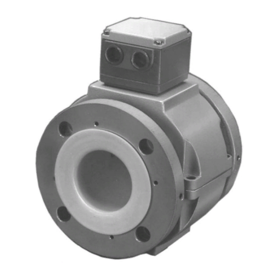
10DS3111E INSTRUCTION MANUAL Table of Contents READ FIRST ............I 1.0 INTRODUCTION . - Page 4 10DS3111E INSTRUCTION MANUAL Figure List FIGURE 1-1. EXPLOSION-PROOF/ CONTINUOUS SUBMERGENCE METER ....1-2 FIGURE 2-1. PROTECTOR PLATES FOR TEFLON LINERS ....... . 2-3 FIGURE 2-2.
- Page 5 10DS3111E INSTRUCTION MANUAL Table List TABLE 1-1. LIQUID TEMPERATURE........... . 1-6 TABLE 1-2.
-
Page 6: Read First
Read these instructions before starting installation; save these instructions for future reference. Contacting the Factory . . . Should assistance be required with any of the company’s products, contact the following: Telephone: 24-Hour Call Center 1-800-HELP-365 E-Mail: [email protected]... - Page 7 10DS3111E INSTRUCTION MANUAL The NEMA 4X rating applies to the meter body and electronics enclosure only. The following accessories (if supplied) may not meet NEMA 4X unless specifically ordered as NEMA 4X: • meter flanges • meter installation hardware: studs, nuts, bolts •...
-
Page 8: Introduction
10DS3111E INSTRUCTION MANUAL 1.0 INTRODUCTION 1.1 General 1.1.1 Description The Series 3000 Magnetic Flowmeter is a compact, volumetric, liquid flow rate detector that uses as the process transducing method the characteristic of a conductive liquid to generate an induced voltage when flowing through a magnetic field. The amplitude of the voltage produced is directly proportional to the flow rate of the metered liquid. - Page 9 10DS3111E INSTRUCTION MANUAL The Primary housing for the continuous submergence and explosion-proof design is different from the other configurations in that it is sealed with a round screw-on ac- cess cover. The interior of this housing is filled with a gelatin-like silicone rubber compound which helps give the meter its waterproof rating.
-
Page 10: Model Number Breakdown
10DS3111E INSTRUCTION MANUAL 1.2 Model Number Breakdown Refer to the data sheet or data tag on the equipment for the model number of the instrument furnished. The details of a specific model number are shown on the following pages. - Page 11 10DS3111E INSTRUCTION MANUAL Model Number Breakdown 10DS3111 Engineering Reference Design Level Meter Lay Length Short Form (WMAG) Replacement for 10D1419 & 10D1465 Replacement for 10D1435 Other Liner Material Hard Rubber Soft Natural Rubber Polyurethane PTFE TEFLON Neoprene Rotomolded TEFZEL Linatex Size inches 1-1/2...
- Page 12 10DS3111E INSTRUCTION MANUAL Model Number Breakdown (continued) 10DS3111 Electrode Material 316 Stn. Steel ® HASTELLOY ® HASTELLOY Titanium Tantalum Platinum / Iridium Zirconium Certification Standard (None) FM Approved-Nonincendive for CL I, Div 2, Gp A,B,C & D; Electrodes Intrinsically Safe forCL I, Div 1, Gp A,B,C &...
-
Page 13: Specifications
10DS3111E INSTRUCTION MANUAL 1.3 Specifications Power Requirements Refer to Section 1.2 Model Number Breakdown. Power Consumption Refer to the signal converter instruction bulletin. Meter Characteristics Meter Size/Flow Ca- Refer to Table 1-4. pacity Span Factory set at specified range between extremes listed in Table 1-4;... - Page 14 10DS3111E INSTRUCTION MANUAL TABLE 1-2. PRESSURE RATING, PSIG (MPa) Maximum Temperature Flange Flange Class Material (130 (180 Pressure PSIG (MPa) Carbon Steel 285 (1.96) 260 (1.79) 255 (1.76) 235 (1.62) 215 (1.48) ANSI 304 SST 275 (1.90) 245 (1.69) 240 (1.76) 215 (1.48) 190 (1.31) Carbon Steel 740 (5.10) 690 (4.76) 680 (4.69) 660 (4.55) 640 (4.41) ANSI 304 SST...
- Page 15 TABLE 1-4. METER CAPACITY VALUES Flow Ranges Capacity Setting 0 to Value Tabulated ( If not specified by Meter Meter customer) Size Capacity* Minimum Maximum L/min inch L/min L/min 16.00 60.0 52.83 2.65 10.0 52.8 200.0 ⁄ 50.0 158.5 7.93 30.0 158.0 600.0...
- Page 16 10DS3111E INSTRUCTION MANUAL Physical Characteristics Outline Dimensions See Figures 2-3 through 2-6 Vibration Limits 1.5 g for 10 - 150 Hz Signal Cable Non-Permanently Installed Cable: (supplied with the 100 ft. (33 m) Max. signal converter) Permanently Installed Cable: Standard Length - 50 feet (16 m) Optional Length - Up to 100 feet (33 m) in 10 foot increments, as specified Materials of...
-
Page 17: Installation
10DS3111E INSTRUCTION MANUAL 2.0 INSTALLATION 2.1 Inspection All meters are shipped in heavy duty containers which are specially designed to provide adequate protection during transit. Since the meter will be operated in conjunction with an electronic signal converter, both instruments may be in the same shipping container. An itemized list of all items included in the shipment is attached to the shipping container. -
Page 18: Meter Handling
10DS3111E INSTRUCTION MANUAL 2.2 Meter Handling When a TEFLON lined meter is specified, two optional liner protector plates (one on each flange face) are factory installed (when specified at time of order). These plates serve to contain the flared ends of the liner, and to prevent damage to the liner during installation and handling. These protector plates are attached to the meter with flat head screws that securely hold the liner in place. - Page 19 10DS3111E INSTRUCTION MANUAL LINER PROTECTOR PLATES, SIZES 1 THROUGH 4 INCHES LINER PROTECTOR/GROUNDING RINGS, SIZES 6 THROUGH 12 INCHES FIGURE 2-1. PROTECTOR PLATES FOR TEFLON LINERS...
- Page 20 10DS3111E INSTRUCTION MANUAL FIGURE 2-2. PROPER HOISTING METHOD Figure is for reference only, the flowmeter shown in this illustration is not the meter described in this instruction bulletin.
-
Page 21: Location
10DS3111E INSTRUCTION MANUAL 2.3 Location The Flowmeter is suitable for either indoor or outdoor installation. When selecting the location of the installation, consideration should be given to the ambient and process temperature limits, as stated in the Specifications Sub-Section 1.3. Several variations of resistance to water-entry are available: •... - Page 22 10DS3111E INSTRUCTION MANUAL Ref. 10D4287 FIGURE 2-3. OUTLINE DIMENSIONS, 1 - 4 INCH FLOWMETER WITH ANSI FLANGES...
- Page 23 10DS3111E INSTRUCTION MANUAL R e f . O D - 1 0 D - 4 1 2 3 r 4 FIGURE 2-4. OUTLINE DIMENSIONS, 6 - 12 INCH FLOWMETER WITH ANSI FLANGES...
- Page 24 10DS3111E INSTRUCTION MANUAL FIGURE 2-5. OUTLINE DIMENSIONS, 6 - 12 INCH FLOWMETER WITH ANSI FLANGES, HI-TEMP...
- Page 25 10DS3111E INSTRUCTION MANUAL Ref. 10D4288 FIGURE 2-6. OUTLINE DIMENSIONS, 1 - 4 INCH FLOWMETER WITH DIN FLANGES...
- Page 26 10DS3111E INSTRUCTION MANUAL FIGURE 2-7. OUTLINE DIMENSIONS, 6 - 12 INCH FLOWMETER WITH DIN FLANGES 2-10...
- Page 27 10DS3111E INSTRUCTION MANUAL FIGURE 2-8. OUTLINE DIMENSIONS, 6 - 12 INCH FLOWMETER WITH DIN FLANGES, HI-TEMP 2-11...
- Page 28 10DS3111E INSTRUCTION MANUAL FIGURE 2-9. OUTLINE DIMENSIONS, 1 - 4 INCH FLOWMETER WITH ANSI FLANGES, CONTINUOUS SUBMERGENCE 2-12...
- Page 29 10DS3111E INSTRUCTION MANUAL FIGURE 2-10. OUTLINE DIMENSIONS, 6 - 12 INCH FLOWMETER WITH ANSI FLANGES, CONTINUOUS SUBMERGENCE 2-13...
- Page 30 10DS3111E INSTRUCTION MANUAL FIGURE 2-11. OUTLINE DIMENSIONS, 1 - 4 INCH FLOWMETER WITH DIN FLANGES, CONTINUOUS SUBMERGENCE 2-14...
- Page 31 10DS3111E INSTRUCTION MANUAL FIGURE 2-12. OUTLINE DIMENSIONS, 6 - 12 INCH FLOWMETER WITH DIN FLANGES, CONTINUOUS SUBMERGENCE 2-15...
-
Page 32: Mounting
10DS3111E INSTRUCTION MANUAL 2.4 Mounting 2.4.1 Orientation The meter may be installed in horizontal, vertical or sloping pipe runs. However, precautions must be taken to assure that the metering tube is filled at all times during measurement. A vertical installation, with the pipe line carrying liquid upwards assures a filled line under low flow rate conditions and also minimizes wear on the meter lining by abrasive grit. - Page 33 10DS3111E INSTRUCTION MANUAL 2.4.3 Torque Specifications It is recommended that the bolts and nuts be lubricated and tightened using a torque wrench. The bolts and nuts should be tightened to approximately 50% of the torque value during the first pass, to approximately 80% during the second pass and to the full torque during the third pass.
- Page 34 10DS3111E INSTRUCTION MANUAL CBI-3007 FIGURE 2-14 . GASKET LOCATIONS 2-18...
- Page 35 FIGURE 2-15. RECOMMENDED PIPING ARRANGEMENT Figure is for reference only, the flowmeter shown in this illustration is not the meter described in this instruction bulletin.
-
Page 36: Grounding Procedure
10DS3111E INSTRUCTION MANUAL 2.5 Grounding Procedure 2.5.1 General Satisfactory operation of metering system requires that careful attention be paid to proper grounding techniques. A good ground is one that is in contact with the earth over a large conductive area. An excellent example of this is a metallic cold water pipe which is underground. -
Page 37: Conductive Pipeline
10DS3111E INSTRUCTION MANUAL 2.5.2 Conductive Pipeline If the meter is included as part of a conductive pipeline that is not electrically insulated from the liquid to be metered, the following grounding procedure should be followed. Refer to Figure 2-16 to supplement the following text. -
Page 38: Non-Conductive Or Electrically Insulated Pipeline
10DS3111E INSTRUCTION MANUAL 2.5.3 Non-Conductive or Electrically Insulated Pipeline If the meter is included as part of a non-conductive or liquid insulated pipeline (such as totally plastic pipe, ceramic lined iron pipe, or cast pipe with internal bitumastic coating), the following grounding procedures apply. -
Page 39: Electrical Interconnection
10DS3111E INSTRUCTION MANUAL 2.6 Electrical Interconnection The Series 3000 Magnetic Flowmeter is furnished with a remotely mounted Signal Converter. Interconnection details are provided in the Instruction Bulletin provided with the Signal Converter. WARNING ELECTRICAL SHOCK HAZARD. Equipment powered by ac line voltage constitutes a potential electric shock hazard to the user. - Page 40 FIGURE 2-19. CONDUIT ENTRY SEAL INSTALLATION...
-
Page 41: Start-Up And Operation
10DS3111E INSTRUCTION MANUAL 3.0 START-UP and OPERATION 3.1 General The meter is calibrated at the factory. Each meter is calibrated to determine its meter capacity at a given velocity. Refer to Table 1-4. Prior to initial system start up, verify that the meter is properly installed; check flow direction, wiring interconnection and grounding as discussed in Section 2.0 Installation. - Page 42 10DS3111E INSTRUCTION MANUAL CUSTOMER CONNECTIONS JUMPER TO BE IN "16A" POSITION GROUND TERMINAL FIGURE 3-2. 10DS3111E PRIMARY CONNECTIONS FOR REMOTE MOUNTED SIGNAL CONVERTER Note: The assembly shown is a "typical" assembly and may not represent the configuration of your specific model. Newer models may be different from the configuration shown.
- Page 43 10DS3111E INSTRUCTION MANUAL CUSTOMER CONNECTIONS FIGURE 3-3. CONTINUOUS SUBMERGENCE PRIMARY CONNECTIONS FOR REMOTE MOUNTED SIGNAL CONVERTER Note: Figure shows electronics without encapsulation material. Normally the converter housing is filled with a silicone rubber encapsulant.
-
Page 44: Functional Description
10DS3111E INSTRUCTION MANUAL 4.0 FUNCTIONAL DESCRIPTION The meter body houses two signal electrodes and two flux producing magnet coils, as shown schematically in Figure 4-1. All flowmeter intraconnection wiring is terminated at a printed circuit assembly located in the base mounted on the meter housing. The meter provides two output signals to the signal converter: •... -
Page 45: Volumetric Flow Rate Measurement
10DS3111E INSTRUCTION MANUAL This may be expressed mathematically as: (Equation #1) E s = α where: = induced electrode voltage B = magnetic field strength D = meter pipe diameter α = dimensionless constant V = liquid velocity The metered liquid constitutes a continuous series of conductive liquid disks moving through a magnetic field. -
Page 46: Operating Characteristics
10DS3111E INSTRUCTION MANUAL (Equation #3) Q = γ E where: Q = volumetric flow rate A = cross-sectional area D = pipe section diameter = induced signal voltage = reference voltage B = magnetic flux density α = dimensionless constant β... - Page 47 10DS3111E INSTRUCTION MANUAL The conductivity of the process liquid (in microsiemens/cm) may be determined from the electrode ac resistance measurement (in megohms) by substitution of values in the following equation. σ - 0.072) x Electrode Diameter, in cm where, 0.072 is the electrode barrier resistance in megohms; i.e., 36 kΩ x 2/10 and, typical electrode diameter is 0.77 cm For example, assuming the measured ac electrode resistance (full pipe) is 192,000 ohms and...
-
Page 48: Liquid Temperature
10DS3111E INSTRUCTION MANUAL 4.2.1.2 Liquid Temperature Having established the minimum liquid conductivity requirements for a given application, any liquid which exhibits equal or higher conductivity may be metered without concern for any system compen- sating adjustments. However, the effect of the liquid conductivity versus temperature should be considered. -
Page 49: Circuit Description
10DS3111E INSTRUCTION MANUAL 5.0 CIRCUIT DESCRIPTION 5.1 Meter Signals The meter body houses two signal electrodes and two flux producing magnet coils. All meter intraconnection wiring is terminated at the CMC/ZERO pc board located in the base of the meter housing. -
Page 50: Maintenance
10DS3111E INSTRUCTION MANUAL 6.0 MAINTENANCE 6.1 General Except for an occasional performance verification check, there is no routine maintenance required for the meter. It is suggested that the meter body not be disassembled. If disassembled, complete waterproof sealing is required for satisfactory operation and is best done at the factory. Replacement of faulty magnet drive coils and electrode replacement is a factory operation. - Page 51 10DS3111E INSTRUCTION MANUAL NOTE The meter housing is supplied as a sealed unit. Therefore, customer field repairs to these meters are not recommended. In the event of a malfunc- tion, repairs should only be performed by a factory field service engineer, or the complete meter returned to the manufacturer for service (shipping charges prepaid).
-
Page 52: Static Test
10DS3111E INSTRUCTION MANUAL 6.3 Static Test If improper operation of the meter is suspected, the following resistance measurements can be made to establish whether an electrical malfunction has occurred. An analog multimeter is required for checking the electrodes. Either an analog or digital multimeter can be used for checking the coils. These measurements can be made at the flowmeter pc board. -
Page 53: Electrode Check
10DS3111E INSTRUCTION MANUAL 6.3.2 Electrode Check The electrode check is essentially a resistance measurement that can be made to establish that a short (or high resistance leakage path) does not exist between one, or both, electrodes and the meter body. Verify that the system power service has been de-energized. To perform this test, the meter must be removed from the pipeline and the meter liner thoroughly dried. -
Page 54: Parts List
10DS3111E INSTRUCTION BULLETIN 7.0 PARTS LIST TABLE 7-1. FLANGE GASKETS FOR METER BODY NOTE Polyurethane and neoprene lined meters use neoprene gaskets. TEFLON lined meters use TEFLON gaskets. Two gaskets are required for each meter. If the meter has grounding rings, two additional gaskets are required for each meter. - Page 55 10DS3111E INSTRUCTION BULLETIN TABLE 7-2. PROTECTOR PLATES FOR TEFLON LINED METERS Order number consists of two protector plates and mounting screws. Grounding rings are not available for this application. When ordering, specify 614B452U__ and suffix from the table below. Meter Size Flange Rating ANSI Class 150 ⁄...
- Page 56 10DS3111E INSTRUCTION BULLETIN TABLE 7-5. GROUNDING RINGS - SIZES 6 THROUGH 12 INCHES NOTE Polyurethane and neoprene lined meters use neoprene gaskets. TEFLON lined meters use TEFLON gaskets. Order number consists of one grounding ring and mounting screws. Order a quantity of two for each meter.
- Page 57 The Company’s policy is one of continuous product improvement and the right is reserved to modify the information contained herein without notice. © 2003 ABB Inc. Printed in USA ABB Inc. ABB Instrumentation Ltd ABB Instrumentation S.p.A ABB Automation Products GmbH 125 East County Line Road Howard Road, St.