Table of Contents
Quick Links
Instruction manual
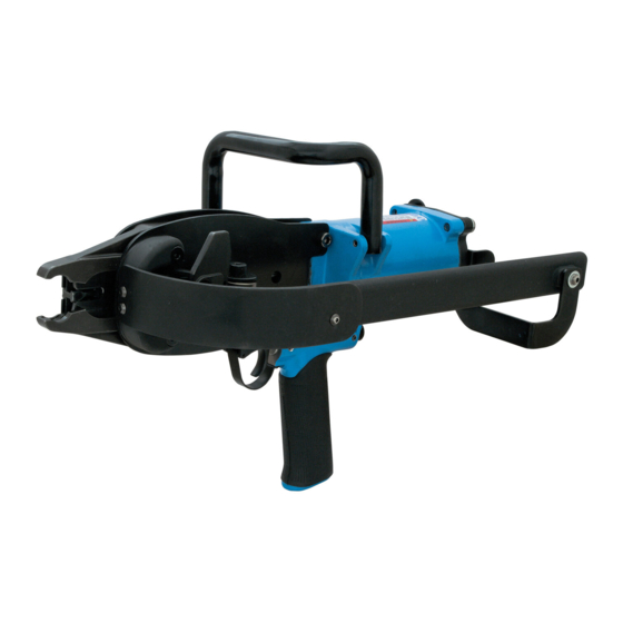
F CL45A GABION TOOL
WARNING
Before operating the pneumatic tool for CL45
Gabion Rings all operators must study this
manual to understand and follow the safety
warnings and instructions.
Keep these instructions with the tool for future
reference. If you have any questions, contact your
distributor.
Table of Contents

Summary of Contents for F CL45A
- Page 1 Instruction manual F CL45A GABION TOOL WARNING Before operating the pneumatic tool for CL45 Gabion Rings all operators must study this manual to understand and follow the safety warnings and instructions. Keep these instructions with the tool for future reference. If you have any questions, contact your...
-
Page 2: Table Of Contents
Index Content Page Tool specifications ........3 Safety instructions ..........4 Lubrication and maintenance ......5 Loading ............6 Operating ............7 Cleaning ............8 Jam clearing ..........9 Trouble shooting ......... 10 Clinchers replacement ........ 17 Blades replacement ........18 Piston O-ring replacement ...... -
Page 3: Tool Specifications
Tool Specifications Dimensions: Height Width Length Weight 370 mm 260 mm 510 mm 6.7 kg 14.57 inch 10.24 inch 20.01 inch 14,75 lbs Min-max operating pressure 6 - 8 bar / 87 - 120 psi Fastener type BECK CL45 Gabion Ring Magazine capacity 100 PCS Vibration Value... -
Page 4: Safety Instructions
Safety Instructions DANGER 1. Read this manual and understand all safety instructions before operation the tool. For any questions, contact an authorized dealer. 2. Never allow to use flammable gases or oxygen as a power source for the tool. Use filtered, lubricated, regulated compressed air only. -
Page 5: Lubrication And Maintenance
Lubrication and Maintenance NOTE Your tool requires lubrication before using it for the first time. Disconnect the air supply from the tool before lubricating. Turn the tool so the inlet is facing up and put one drop of pneumatic oil into the air inlet. -
Page 6: Loading
Loading Disconnect the air supply. Pull the pusher back and hang it on feeder arm. Insert a strip of appropriate Gabion CL45 rings from the backside into the magazine. Move the rings to the front. Put the pusher back on the magazine and position it against the end of the ring strip. -
Page 7: Operating
Operating Protect your eyes and ears. Wear safety glasses with WARNING side shields. Wear hearing protection. Employers and operators are responsible for ensuring the user or anyone near the tool wear this safety protection. To prevent accidental injuries: never place a hand or any WARNING other body part in the clinching area. -
Page 8: Cleaning
Cleaning DANGER Never use gasoline or other flammable liquids to clean the tool. Vapors in the tool can ignite by a spark and cause the tool to explode. This may result in death or serious injury. 1. Disconnect the tool from the air supply. -
Page 9: Jam Clearing
Jam clearing Disconnect the air supply. Unload the tool completely. No fasteners may remain in the magazine. Clear the jamming ring by using a manual plier. -
Page 10: Trouble Shooting
Trouble Shooting Problem Cause Solution Inside diameter of Slot (440195.3) worn Replace slot (440195.3) ring too big after clinching Wrong slot (too short) used Verify and replace slot (440195.3) if necessary (440195.3) Slot plate broken Replace slot plate (294247) (294247) Wrong piston rod (288458) Verify and replace piston (too short) - Page 11 Problem Cause Solution Inside diameter of Wrong clinchers Verify and eventually ring too small after (184206,184207) replace clinchers (184176, clinching 184177) Clinchers stop worn or Replace clinchers polished off Ring points not en- Tip of clinchers broken Replace clinchers tering into opposite clincher Mismatching clinchers.
- Page 12 Problem Cause Solution Ring drops instead Slot (440195.3) worn Replace slot (440195.3) of forming correctly Wrong slot, too short Verify and replace slot (440195.3) if necessary (440195.3) Slot plate (294247) bent or Replace slot plate broken. This plate must (294247) keep the slot (440195.3) tightly against the end of the side plate (294248)
- Page 13 Problem Cause Solution Rings jam Magazine (170230.1) Magazine (170230.1) 1.Damaged or bent 1.Replace magazine (changes position of (170230.1) magazine shoe (520015) 2. Replace magazine shoe 2. Too many shims. Ring Ring groove (520015) passes under maga- zine shoe (520015) without raising maga- zine shoe (520015);...
- Page 14 Problem Cause Solution Rings jam Defective rings Send sample of rings to 1.Burrs your distributor to be tested 2.Rings skewed on stick 3.Rings out of line on stick 4.Rings twisted 5.Rings not symmetrical 6.Rings strip flare at the ends Wrong wire gauge Verify wire size 11 gauge / 3.0mm Rings don’t feed...
- Page 15 Problem Cause Solution Ring spitting Build up of material in Remove material clinchers helix (when using plated, aluminum or plastic coated rings) Snapping noise as Defective rings ring is being fed 1. Burr on outside curve of Send ring samples to your from magazine ring distributor to be tested...
- Page 16 Problem Cause Solution Rear valve’s seat (140349) Leaking when Adjust the position of rear valve’s seat (140349) fighting is not at the right position Worn O-ring Replace O-ring The tool is designed to operate with rings manufactured within standard tolerances. As can be seen in the preceding pages, visibly defective rings can be the cause of many ring-forming troubles.
-
Page 17: Clinchers Replacement
Replace Clinchers Disconnect the air supply and remove rings from magazine. Loosen Screw and nut with M5 Hex. Wrench key and M17 spanner. Take away screw, nut, washer, lash, spring, clinchers, bushings, bracket and washer. Replace clinchers and bushings. Note Clinchers and bushings should be replaced only in pairs. -
Page 18: Blades Replacement
Replace Blades Disconnect the air supply and remove rings from magazine. Remove screw with M3 Hex. wrench key. Take away screw, rear cap and packing with M5 Hex. wrench key. Remove screw, nut, washer, latch spring, clinchers, magazine, washer and latch with M5 Hex. - Page 19 Take away screw, nut, side plates and throttle’s stem with M6 Hex. wrench key and M13 Take away pin, roller and blade. Replace blade.
-
Page 20: Piston O-Ring Replacement
Replace Piston‘s O-Ring Disconnect the air supply and remove rings from magazine. Remove screw. Take away screw, rear cap and packing with M5 Hex. wrench key. Remove screw, nut, washer, latch spring, clinchers, magazine, washer and latch with M5 Hex. wrench key and M17 Spanner. - Page 21 Take away screw, nut, side plates and throttle’s stem with M6 Hex. wrench key and M13 Take away pin, roller and blade. Push piston rod up. Take away nut with M16 Spanner and pliers. Then, take away piston and piston rod. Replace piston’s O-ring.
-
Page 22: Valve O-Ring Replacement
Replace valve’s O-ring Disconnect the air supply and remove rings from magazine Remove screw. Take away screw, rear cap and packing with M5 Hex. wrench key. Remove screw, nut, washer, latch spring, clinchers, magazine, washer and latch with M5 Hex. wrench key and M17 Spanner. - Page 23 Loosen to screw with M2 Hex. wrench key. Loosen and take away throttle stem and font valve seat. Remove screw and deflector with M3 Hex. wrench key. Take away rear valve’s seat and spring with flat screw driver. Loosen and take away screw, washer, O-ring end support, O-ring, O-ring center support and spacer with two pieces M3 Hex.
- Page 24 Reassemble font valve seat, let top of font valve seat 0.8mm higher than body. Reassemble spring and rear valve’s seat. Connect air supply. Reassemble throttle stem. If leaking when not shooting, then adjust the position of font valve seat. If leaking when shooting, then adjusting the position of rear valve’s seat.
-
Page 25: Pusher Spring Replacement
Replace pusher spring Disconnect the air supply and remove rings from the magazine. Remove screw and nut with M5 Hex. wrench key and M17 spanner. Disassemble screw, nut, washer, latch spring, clinchers, bushing and bracket. Disassemble screw and nut with M5 Hex. - Page 26 FASCO S.r.l. Via B. Buozzi 2 40057 Cadriano di Granarolo (BO) Italy Tel. +39 051 60181 Mail: [email protected] Homepage: www.fasco-tools.com...