
Related Manuals for Siemens SIMATIC NET RUGGEDCOM RS969


Summary of Contents for Siemens SIMATIC NET RUGGEDCOM RS969
- Page 1 Installation Manual SIMATIC NET Rugged Ethernet Switches RUGGEDCOM RS969 Edition 01/2021 https://www.siemens.com...
- Page 2 Preface Introduction Installing the Device SIMATIC NET Device Management Rugged Ethernet Switches RUGGEDCOM RS969 Communication Ports Technical Specifications Installation Manual Accessories Certification 01/2021 C79000-G8976-1038-03...
- Page 3 Note the following: WARNING Siemens products may only be used for the applications described in the catalog and in the relevant technical documentation. If products and components from other manufacturers are used, these must be recommended or approved by Siemens. Proper transport, storage, installation, assembly, commissioning, operation and maintenance are required to ensure that the products operate safely and without any problems.
-
Page 4: Table Of Contents
Accessing Documentation ....................... v Registered Trademarks ......................v Warranty ..........................v Training ..........................vi Customer Support ........................vi Contacting Siemens ....................... vii Introduction ........................... 1 Feature Highlights ....................1 Description ......................2 Required Tools and Materials ................. 5 Decommissioning and Disposal ................6 Cabling Recommendations .................. - Page 5 Table of Contents Fiber Optic Ethernet Port Specifications ............... 26 Operating Environment ..................26 Mechanical Specifications ..................27 Dimension Drawings ................... 27 Accessories .......................... 31 Power (1/unit) ..................... 31 Console (1/unit) ....................32 Failsafe (1/unit) ....................33 Ethernet (8/unit) ....................34 LC Fiber Optic (2/unit) ..................
-
Page 6: Preface
Warranty Siemens warrants this product for a period of five (5) years from the date of purchase, conditional upon the return to factory for maintenance during the warranty term. This product contains no user-serviceable parts. Attempted service by unauthorized personnel shall render all warranties null and void. -
Page 7: Training
Siemens Sales representative. Customer Support Customer support is available 24 hours, 7 days a week for all Siemens customers. For technical support or general information, contact Siemens Customer Support through any of the following methods: Online Visit http://www.siemens.com/automation/support-request... -
Page 8: Contacting Siemens
Preface Contacting Siemens • Ask questions or share knowledge with fellow Siemens customers and the support community Contacting Siemens Address Siemens AG Industry Sector 300 Applewood Crescent Concord, Ontario Canada, L4K 5C7 Telephone Toll-free: 1 888 264 0006 Tel: +1 905 856 5288... - Page 9 Preface Contacting Siemens viii RUGGEDCOM RS969 Installation Manual, 01/2021, C79000-G8976-1038-03...
-
Page 10: Introduction
Introduction The RUGGEDCOM RS969 is an industrially hardened, fully managed Ethernet switch providing dual fiber optical Fast Ethernet or Gigabit ports and eight Fast Ethernet copper ports in an IP65/IP67 rated package for protection against low pressure jets of water (IP65) or temporary immersion in water (IP67). Designed to operate reliably in harsh industrial environments the RUGGEDCOM RS969 provides a high level of immunity to electromagnetic interference and heavy electrical surges typical of environments found in electric utility substations, factory... -
Page 11: Description
Introduction 1.2 Description • Failsafe output relay for critical failure or error alarming Universal Power Supply Options • Fully integrated power supply • Universal high-voltage range: 88-300 VDC or 85-264 VAC. • Popular low-voltage DC ranges: 12, 24, 48 VDC • Dual redundant, parallel load-sharing power supplies (option) •... - Page 12 Introduction 1.2 Description Copper Ethernet Ports Port Status LED POWER 1 LED POWER 2 LED ALARM LED RS-232 Console Port Failsafe Output Relay M12 Power Supply Port Fiber Optic Ethernet Ports RUGGEDCOM RS969 Installation Manual, 01/2021, C79000-G8976-1038-03...
- Page 13 Introduction 1.2 Description Surge Ground Connection Chassis Ground Connection Figure 1.1 RUGGEDCOM RS969 (M12 Connectors Shown) Copper Ethernet Ports Port Status LED POWER 1 LED RUGGEDCOM RS969 Installation Manual, 01/2021, C79000-G8976-1038-03...
-
Page 14: Required Tools And Materials
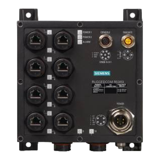
Introduction 1.3 Required Tools and Materials POWER 2 LED ALARM LED RS-232 Console Port Failsafe Output Relay M23 Power Supply Port Fiber Optic Ethernet Ports Surge Ground Connection Chassis Ground Connection Figure 1.2 RUGGEDCOM RS969 (RJ45 Connectors Shown) Port Status LED Indicate the status of each port. State Description Yellow (Solid) -
Page 15: Decommissioning And Disposal
Siemens recommends using RUGGEDCOM industrial Ethernet shielded cables for all Ethernet ports. Siemens does not recommend the use of copper cabling of any length for critical, real-time substation automation applications. All copper Ethernet ports on RUGGEDCOM products include transient suppression circuitry to protect against damage from electrical transients and conform with IEC 61850-3 and IEEE 1613 Class 1 standards. -
Page 16: Ingress Protection
Introduction 1.6 Ingress Protection Cable Type Wavelength (nm) Modal Bandwidth Distance (m) (MHz·km) 100Base-FX 1000Base-SX 10GBase-SR 1300 2000 — — OM4 (50/125) 3500 — 1300 2000 — — Laser optimized. Ingress Protection IEC International Standard 60529 (Edition 2.1: 2001-02) is a "classification of degrees of protection provided by enclosures as a system for specifying the enclosures of electrical equipment on the basis of the degree of protection provided by the enclosure."... - Page 17 Introduction 1.6 Ingress Protection RUGGEDCOM RS969 Installation Manual, 01/2021, C79000-G8976-1038-03...
-
Page 18: Installing The Device
This product contains no user-serviceable parts. Attempted service by unauthorized personnel shall render all warranties null and void. Changes or modifications not expressly approved by Siemens AG could invalidate specifications, test results, and agency approvals, and void the user's authority to operate the equipment. -
Page 19: Mounting The Device
Installing the Device 2.2 Mounting the Device IMPORTANT If any item is missing or damaged, contact Siemens for assistance. Mounting the Device The RUGGEDCOM RS969 is designed to be mounted on a panel by affixing the top and bottom flanges of the device to a panel using screws. -
Page 20: Connecting The Failsafe Alarm Relay
Installing the Device 2.3 Connecting the Failsafe Alarm Relay To mount the device to a panel, do the following: Place the device against the panel and align the flanges with the mounting holes. Flange Figure 2.1 Panel Mounting (Typical) Install the supplied screws to secure the flanges to the panel. Connecting the Failsafe Alarm Relay The Failsafe output relay is provided to signal critical error conditions that may occur on the RUGGEDCOM RS969 series switches. -
Page 21: Connecting Power
Installing the Device 2.4 Connecting Power The proper relay connections are as follows: Description Normally Closed Common Normally Open Figure 2.2 Failsafe Alarm Relay Wiring Connecting Power The RUGGEDCOM RS969 is equipped with either a Mini or M23 A-coded male power supply input connector. - Page 22 Installing the Device 2.4.1 Power Supply Connector Pin-Out Terminal # Description Usage PS1 Live/+ PS1 Live/+ is connected to the positive (+) terminal if the power source is DC or to the (Live) terminal if the power source is AC. Chassis Ground Chassis Ground is connected to the Safety Ground terminal for AC inputs or the equipment ground bus for DC inputs.
-
Page 23: 2.4.2 Power Supply Wiring
Installing the Device 2.4.2 Power Supply Wiring 2.4.2 Power Supply Wiring The following illustrates how to connect the RUGGEDCOM RS969 to a single or dual power supplies. Note • For 100-240 VAC rated equipment, a 250 VAC appropriately rated circuit breaker must be installed. - Page 24 Installing the Device 2.4.2 Power Supply Wiring M23 Power Connector Neutral Safety Line 250 VAC Breaker 110/230 VAC Power Source Safety Earth Figure 2.6 AC Power Supply Wiring Example (M23 Power Connector) Single Low DC Power Supply Wiring Mini Power Connector Ground Bus 300 VDC Breaker DC Power Source Figure 2.7...
- Page 25 Installing the Device 2.4.2 Power Supply Wiring M23 Power Connector Ground Bus 300 VDC Breaker DC Power Source Figure 2.8 DC Power Supply Wiring Example (M23 Connector) Dual AC/DC Power Supply Wiring (M23 Connector Only) M23 Power Connector Ground Bus Line 250 VAC Breaker Neutral 110/230 VAC Power Source (PS2) 110/230 VAC Power Source (PS1)
- Page 26 Installing the Device 2.4.2 Power Supply Wiring M23 Power Connector Ground Bus Line 250 VAC Breaker 110/230 VAC Power Source (PS2) Neutral Safety 300 VDC Breaker DC Power Source (PS1) Figure 2.10 AC and DC Power Supply Wiring Example M23 Power Connector Ground Bus 300 VDC Breaker DC Power Source (PS2)
-
Page 27: 2.4.3 Disabling Line-To-Ground Transient Protection
Installing the Device 2.4.3 Disabling Line-to-Ground Transient Protection 2.4.3 Disabling Line-to-Ground Transient Protection All line-to-ground transient energy is shunted to the Surge Ground terminal. In cases where users require the inputs to be isolated from ground, remove the ground braid between Surge and Chassis Ground. All line-to-ground transient protection circuitry will be disabled. -
Page 28: Device Management
Device Management This section describes how to connect to and manage the device. Connecting to the Device The following describes the various methods for accessing the RUGGEDCOM RS969 console and Web interfaces on the device. For more detailed instructions, refer to the RUGGEDCOM RS969 User Guide for the RUGGEDCOM RS969. -
Page 29: Configuring The Device
Device Management 3.2 Configuring the Device For more information about available ports, refer to "Communication Ports (Page 21)". Configuring the Device Once the device is installed and connected to the network, it must be configured. All configuration management is done via the RUGGEDCOM RUGGEDCOM RS969 interface. -
Page 30: Communication Ports
Communication Ports The RUGGEDCOM RS969 can be equipped with various types of communication ports to enhance its abilities and performance. To determine which ports are equipped on the device, refer to the factory data file available through RUGGEDCOM RS969 . For more information on how to access the factory data file, refer to the RUGGEDCOM RS969 User Guide for the RUGGEDCOM RS969. -
Page 31: Copper Ethernet Ports
Communication Ports 4.1 Copper Ethernet Ports RJ45 Copper Ethernet Ports Fiber Optic Ethernet Ports Figure 4.2 Port Assignment (RJ45 Connectors Shown) Copper Ethernet Ports The RUGGEDCOM RS969 supports eight 10/100Base-TX Ethernet ports that allow connection to standard Category 5 (CAT-5) unshielded twisted-pair (UTP) cables with RJ45 male connectors or M12 male connectors. -
Page 32: Fiber Optic Ethernet Ports
Communication Ports 4.2 Fiber Optic Ethernet Ports Pin-Out (RJ45) The following is the pin-out description for the RJ45 connectors: 10/100Base- Description TX Signal Receive Data+ Receive Data- Transmit Data+ Figure 4.3 RJ45 Ethernet Port Pin Reserved (Do Not Connect) Configuration Reserved (Do Not Connect) Transmit Data- Reserved (Do Not Connect) Reserved (Do Not Connect) - Page 33 Communication Ports 4.2 Fiber Optic Ethernet Ports Rx Connector Figure 4.5 LC Port For specifications on the available fiber optic Ethernet ports, refer to "Fiber Optic Ethernet Port Specifications (Page 26)". RUGGEDCOM RS969 Installation Manual, 01/2021, C79000-G8976-1038-03...
-
Page 34: Technical Specifications
Technical Specifications This section details the specifications and operating conditions of the device. Power Supply Specifications Power Minimum Maximum Internal Isolation Maximum Supply Type Input Input Fuse Rating Power Consumption 12–24 VDC 10 VDC 36 VDC 3.15A (T) 1.5 kVDC 10 W 24 VDC 18 VDC... -
Page 35: Fiber Optic Ethernet Port Specifications
All cabling is duplex type unless otherwise specified. • Maximum segment length is greatly dependent on factors such as fiber quality, and the number of patches and splices. Consult a Siemens sales associate when determining maximum segment distances. • All optical power numbers are listed as dBm averages. To convert from average to peak, add 3 dBm. -
Page 36: Mechanical Specifications
Technical Specifications 5.6 Mechanical Specifications Ambient Storage -40 to 85° C (-40 to 185° F) Temperature Ambient Relative 5% to 95% Humidity Maximum Altitude 2000 m (6562 ft) Measured from a 30 cm (12 in) radius surrounding the center of the RUGGEDCOM RS969 enclosure. Non-condensing Over temperature range of -40 to 85 °C (-40 to 185 °F) Mechanical Specifications... - Page 37 Technical Specifications 5.7 Dimension Drawings Figure 5.1 M12 Connectors RUGGEDCOM RS969 Installation Manual, 01/2021, C79000-G8976-1038-03...
- Page 38 Technical Specifications 5.7 Dimension Drawings Figure 5.2 RJ45 Connectors RUGGEDCOM RS969 Installation Manual, 01/2021, C79000-G8976-1038-03...
- Page 39 Technical Specifications 5.7 Dimension Drawings RUGGEDCOM RS969 Installation Manual, 01/2021, C79000-G8976-1038-03...
-
Page 40: Accessories
Accessories This chapter details the various accessories available for the RUGGEDCOM RS969. Power (1/unit) M23 Power Mating Connector • Description M23 5pin female connector, 600V, IP68 rated • Order Code 99-60-0007 • Cable Specifications 3/18 AWG, jacket OD range 0.20" - 0.48"... -
Page 41: Console (1/Unit)
Accessories 6.2 Console (1/unit) Console (1/unit) M12 Console Port Mating Cable Description • M12 8pin A-code male to DB9 female; unshielded, PUR jacket cable, 30V/4A, 3m • Order Code 99-43-0023-001 • Cable Specifications M12 8pin A-code male to free end, Figure 6.3 M12 Console Port Mating Cable M12 Console Port Mating Connector... -
Page 42: Failsafe (1/Unit)
Accessories 6.3 Failsafe (1/unit) Failsafe (1/unit) M12 FailSafe Port Mating Cable Description • M12 4pole A-coded; unshielded, PUR Jacket cable, 3m • Order Code 99-43-0024-001 Figure 6.5 M12 FailSafe Port Mating Cable M12 FailSafe Port Mating Connector • Description M12-straight plug, 4 pole, A-coded, IP67 rated Order Code •... -
Page 43: Ethernet (8/Unit)
Accessories 6.4 Ethernet (8/unit) Ethernet (8/unit) M12 D-code Ethernet Port Mating Cable Description • M12 D-code to RJ45; patch cable, 3meters • Order Code 99-43-0040-001 • Cable Specifications M12 D-code male 4 pin, CAT5e, 3m Figure 6.7 M12 D-code Ethernet Port Mating Cable M12 D-code Ethernet Port Mating Connector •... - Page 44 Accessories 6.4 Ethernet (8/unit) M12 D-Code Ethernet Port Mating Cable • Description M12 male D-code to male D-code; shielded PUR jacket patch cable, 5 meters Order Code • 99-43-0041-001 • Cable Specifications M12 male 4 pin, CAT 5e, 5m Figure 6.9 M12 D-Code Ethernet Port Mating Cable IP67 RJ45 Ethernet Port Mating Cable •...
-
Page 45: Lc Fiber Optic (2/Unit)
Accessories 6.5 LC Fiber Optic (2/unit) Figure 6.11 IP67 RJ45 Ethernet Port Mating Connector LC Fiber Optic (2/unit) LC Port Mating Connector • Description IP67 Multimode LC plug • Order Code 99-60-0006 Figure 6.12 LC Port Mating Connector • Description IP67 Singlemode LC plug Order Code •... - Page 46 Accessories 6.5 LC Fiber Optic (2/unit) • Description Multimode IP67 LC plug to LC connector, 3m • Order Code 99-43-0056-001 Figure 6.14 LC Port Mating Connector • Description Singlemode IP67 LC plug to LC connector, 3m • Order Code 99-43-0054-001 Figure 6.15 LC Port Mating Connector LC Port Mating Connector •...
- Page 47 Accessories 6.5 LC Fiber Optic (2/unit) RUGGEDCOM RS969 Installation Manual, 01/2021, C79000-G8976-1038-03...
-
Page 48: Certification
UL 62368-1 Information Technology Equipment – Safety Part 1: General Requirements 7.1.2 European Commission (EC) This device is declared by Siemens AG to comply with essential requirements and other relevant provisions of the following EC directives: • EN 60950-1 Information Technology Equipment – Safety – Part 1: General Requirements •... -
Page 49: 7.1.3 Fcc
Methods of Measurement The device is marked with a CE marking and can be used throughout the European community. A copy of the CE Declaration of Conformity is available from Siemens AG. For contact information, refer to "Contacting Siemens (Page vii)". -
Page 50: Iso
Support at https://support.industry.siemens.com/cs/ww/en/view/89855782. 7.1.8 RoHS This device is declared by Siemens AG to meet the requirements of the following RoHS (Restriction of Hazardous Substances) directives for the restricted use of certain hazardous substances in electrical and electronic equipment: China RoHS 2 •... -
Page 51: 7.1.9 Other Approvals
Certification 7.1.9 Other Approvals 7.1.9 Other Approvals This device meets the requirements of the following additional standards: • IEEE 1613 IEEE Standard Environmental and Testing Requirements for Communications Networking Devices in Electric Power Substations • IEC 61000-6-2 Electromagnetic Compatibility (EMC) – Part 6-2: Generic Standards – Immunity for Industrial Environments •... -
Page 52: Emc And Environmental Type Tests
Certification 7.3 EMC and Environmental Type Tests Test Description High Temperature Method 501.4 Procedure I Storage High Temperature Method 501.4 Procedure II Operational Low Temperature Method 502.4 Procedure I Storage Low Temperature Method 502.4 Procedure II Operational Temperature Shock Method 503.4 Procedure I Storage Acceleration Method 513.5 Procedure II Salt Fog Method 509.4 Procedure I Vibration Method 514.5... - Page 53 Certification 7.3 EMC and Environmental Type Tests Test Description Test Levels Severity Levels IEC 61000-4-29 Voltage Dips DC Power ports 30% for 0.1 s, 60% for — & Interrupts 0.1 s, 100% for 0.05 s AC Power ports 30% for 1 period, —...
- Page 54 Certification 7.3 EMC and Environmental Type Tests Description Test Levels HV Impulse Signal ports 5 kV (Failsafe Relay) DC Power ports 5 kV AC Power ports 5 kV Dielectric Strength Signal ports 2 kV (Failsafe Relay) DC Power ports 1.5 kV AC Power ports 2 kV Environmental Type Tests...
- Page 55 Certification 7.3 EMC and Environmental Type Tests RUGGEDCOM RS969 Installation Manual, 01/2021, C79000-G8976-1038-03...
- Page 56 Further Information Siemens RUGGEDCOM https://www.siemens.com/ruggedcom Industry Online Support (service and support) https://support.industry.siemens.com Industry Mall https://mall.industry.siemens.com Siemens AG Digital Industry Process Automation Postfach 48 48 90026 NÜRNBERG GERMANY...