Table of Contents
Quick Links
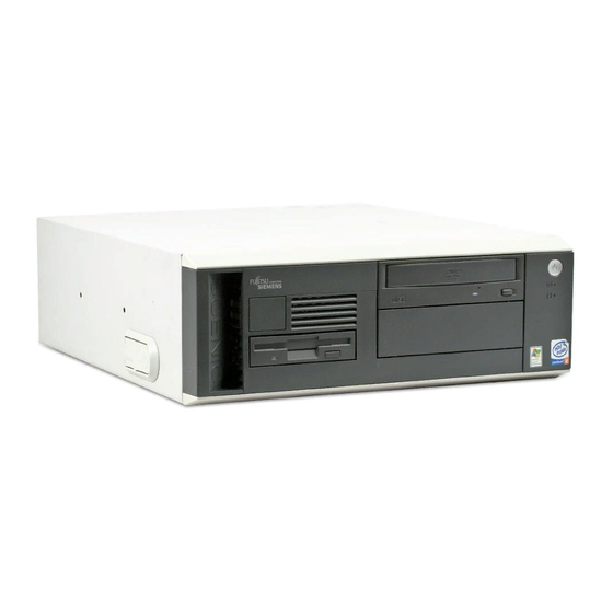
DESKPOWER N300 Series User's Manual
Fujitsu endeavours to ensure that the information in this document is correct, but accepts no liability
for any error or omission in the same. Any procedures described in this document for operating Fujitsu
products should be read and understood by the operator before such products are used. To ensure
that Fujitsu products function without risk to safety and health, such procedures should be strictly
observed by the operator. The development of Fujitsu products and services is continuous and
published information may not be up to date. Any particular issue of a product may contain facilities
not described herein. It is important to check the current position with Fujitsu. Specifications and
statements as to performance in this document are Fujitsu estimates intended for general guidance.
They may require adjustment in particular circumstances and should therefore not be taken as formal
offers or commitments.
DESKPOWER is a trademark of Fujitsu Limited. The following are registered trademarks of Microsoft
Corporation: MS, MS-DOS, Windows
®
NT, Windows
®
98, Windows Millennium, Window
®
2000 and
Windows XP.
Intel and Pentium are registered trademarks of Intel Corporation in the U.S.
Celeron is a registered trademark of Intel Corporation in the U.S.
Other product names are trademarks or registered trademarks of respective companies.
Other products are copyrighted by individual companies.
All other trademarks referenced are trademarks or registered trademarks of their respective owners,
whose protected rights are acknowledged.
Copyright
©
Fujitsu PC Asia Pacific
All rights, including rights of translation, reproduction by printing, copying or similar methods, in part
or in whole, are reserved.
Offenders will be liable for damages.
All rights, including rights created by patent grant or registration of a utility model or design, are reserved.
Delivery subject to availability. Right of teachnical modification reserved.
DECLARATION OF CONFORMITY
according to FCC Part 15 Class B
This device complies with Part 15 Class B of the FCC Rules. Operations are subject to the following
two conditions:
(1) This device may not be allowed to cause harmful interference, (2) This device must accept any
interference received, including interference that may cause undesired operation.
Wesbite: www.fujitsu-pc-asia.com
i
Table of Contents

Related Manuals for Fujitsu DESKPOWER N300 Series


Summary of Contents for Fujitsu DESKPOWER N300 Series
- Page 1 Fujitsu endeavours to ensure that the information in this document is correct, but accepts no liability for any error or omission in the same. Any procedures described in this document for operating Fujitsu products should be read and understood by the operator before such products are used. To ensure that Fujitsu products function without risk to safety and health, such procedures should be strictly observed by the operator.
- Page 2 IMPORTANT SAFETY INSTRUCTIONS 1. Read these instructions carefully. Save these instructions for future reference. 2. Follow all warnings and instructions marked on the product. 3. Unplug this product from the wall outlet before cleaning. Do not use liquid cleaners or aerosol cleaners.
- Page 3 13. Unplug this product from the wall outlet and refer servicing to qualified service personnel under the following conditions: a. When the power cord or plug is damaged or frayed. b. If liquid has been spilled into the product. c. If the product has been exposed to rain or water. d.
- Page 4 Make sure that you read the manual when using this product. Fujitsu, as a member of the International Energy Star Program, recognizes that this equipment is compliant with the standard of the International Energy Star Program.
- Page 5 Using this Product for High-Safety Applications This product is for office, personal, home, ordinary industry and other general use. It is not designed and manufactured for use in high-safety applications. Do not use this product for such applications without taking measures to satisfy the high-safety requirements.
- Page 6 Microsoft Service Pack Microsoft Corp. offers Service Pack to provide the users of Microsoft ® Windows ® with more stable system operation (http://www.microsoft.com/). ® The latest version of the Service Pack helps you configure the most stable system using Microsoft ®...
- Page 7 Conventions Used in This Manual Introduction This manual tells you how to put your PC into operation and how to operate it in daily use. Depending on the configuration level chosen some of the hardware components described may not be available on your PC. Please observe the notes on your operating system. You can incorporate operable drives (for example DAT drive) as well as other boards.
- Page 8 Important Notes In this chapter you will find information regarding safety which is essential to take note of when working with your PC. The manufacturer's notes contain helpful information on your PC. Safety CAUTION During installation and before operating the device, please observe the instructions on environmental conditions in the chapter entitled "Technical data"...
- Page 9 Fujitsu is not responsible for any radio or television interference caused by unauthorised modifications of this equipment or the substitution or attachment of connecting cables and equipment other than those specified by Fujitsu. The correction of interference caused by such unauthorised modification, substitution or attachment will be the responsibility of the user.
- Page 10 Transporting the PC CAUTION Transport all parts separately in their original packaging or in a packaging which protects them from knocks and jolts, to the new site. Do not unpack them until all transportation manoeuvres are completed. Never drop the monitor! Cleaning the PC CAUTION Turn off all power and equipment switches and remove the power plug from the mains supply.
- Page 11 Disposal and recycling This device has been manufactured to the highest possible degree from materials which can be recycled or disposed of in a manner that is not environmentally damaging. The device may be taken back after use to be recycled, provided that it is returned in a condition that is the result of normal use. Any components not reclaimed will be disposed of in an environmentally acceptable manner.
- Page 12 Warning and caution labels Your PC bears the warning and caution labels as shown below. The warning and caution labels must not be removed or damaged. Rear of the PC main unit To prevent electric shock, WARNING switch off the PC and connected peripherals and Electric shock unplug power cords from...
- Page 13 Organization of This Manual Before Reading This Manual This section contains cautions for safe operation, representations and symbols used in this manual. Be sure to read this first! Chapter Preparing for Use This chapter provides the names and functions of individual parts. Chapter Operation This section describes the location of installation and installation of the computer.
-
Page 14: Table Of Contents
Contents CHAPTER 1 Preparing for Use 1 Preparing for Use ................2 Unpacking and Checking the Delivery ............. 2 Steps for Initial Setup ..................2 Setting Up the PC .................... 3 Connect the Monitor, Mouse and Keyboard ............. 3 Connecting the PC to the Mains Voltage ............5 Initial Switch-on: Software will be Installed ............ - Page 15 CHAPTER 4 System Expansion 1 System Expansions ................ 28 Information about Boards ................28 Opening the Casing ..................29 Closing the Casing ..................30 Installing a Board ................... 31 Removing a Board ..................32 Low-Profiles Boards ..................33 Installing an Additional Serial Port ..............34 Installing and Removing Drives ..............
-
Page 16: Chapter 1 Preparing For Use
CHAPTER 1 Preparing for Use... -
Page 17: Preparing For Use
1 Preparing for Use CAUTION Please take note of the safety information in the "Important notes" chapter. Unpacking and Checking the Delivery It is recommended not to throw away the original packaging material! It may be required for reshipment at some later date. Unpack all the individual parts. -
Page 18: Setting Up The Pc
Setting Up the PC CAUTION When installing your PC, give consideration to the recommendations and safety notes. Set up the PC only in its correct orientation. The points to observe are illustrated on the following pages. We recommend that you place your equipment on a surface with good anti-slip qualities. In view of the multitude of different finishes and varnishes used on furniture, it is possible that the rubber feet of the devices will mark the surface they stand on. - Page 19 Connecting the mouse Connecting a PS/2 mouse Connect the PS/2 mouse to the PS/2 mouse port on the system unit. Connecting USB mouse Connect the USB mouse to the USB port on the system unit. If you do not attach a mouse at the PS/2 mouse port , you can disable the mouse controller in the BIOS Setup in order to free the IRQ12 for a different application.
-
Page 20: Connecting The Pc To The Mains Voltage
Connecting the PC to the Mains Voltage 100 V - 127 V 200 V - 240 V Check the voltage setting. CAUTION Devices with main power switch: Some units with a main power switch have a wide-range power supply, depending on the configuration level. -
Page 21: Initial Switch-On: Software Will Be Installed
Plug the system unit's power cable into the system unit (1) and then into the grounded mains outlet (2). Initial Switch-on: Software will be Installed If the PC is connected to a network, the network protocol is required as well as the user and server details. - Page 22 Switching on PC with devices with main power switch ON/OFF switch Press the ON/OFF switch on the front of the PC. The power-on indicator lights green and the PC is started. Installing the software During installation, follow the instructions on screen. Consult the operating system manual if there is anything unclear about the requested input data.
-
Page 23: Connecting External Devices
Connecting External Devices CAUTION Do not connect or disconnect cables during a thunderstorm. Always take hold of the actual plug. Never unplug a cable by pulling the cable itself. Connect and disconnect the cables in the order described below. With the exception of USB devices, always remove all power plugs before connecting external devices! Read the documentation on the external device before connecting it. - Page 24 Connections on the system unit The ports for external devices are on the rear and on the front of the system unit. The ports available on your PC depend on the configuration level you have selected. The standard ports are marked with the symbols shown below (or similar).
- Page 25 Connecting external devices to the serial port External devices can be connected to the serial port (e.g. a modem). Connect the data cable to the external device. Connect the data cable to the serial port For an exact description of how to connect external devices to the serial port , please refer to the device documentation.
-
Page 26: Chapter 2 Operation
CHAPTER 2 Operation... -
Page 27: Operation
1 Operation Switching On the PC Switch the monitor on (see the operating manual for the monitor). On devices with main power switch Switch the PC on with the main power switch on the back panel. If the power-on indicator lights orange or flashes green/orange, press the power button on the front of the casing. -
Page 28: Switching Off The Pc
Switching Off the PC On devices with main power switch Shut down the operating system properly. For Windows: select Shut Down from the Start menu. If the operating system does not automatically switch off the PC, switch the PC to ready to operate by pressing the power button or turn it off by pressing the main power switch when requested to do so. -
Page 29: Indicators On The Pc
I Indicators on the PC The indicators are on the front of the casing. Hard disk indicator The indicator lights up when the hard disk drive of the PC is accessed. Power-on indicator – The indicator lights green: The PC is on. –... -
Page 30: Keyboard
2 Keyboard 9 10 13 14 15 16 17 18 Esc key Pressing this key cancels the operation the application program is executing. F keys These F keys are assigned specific functions for each application. Back space key Press the Back Space key to move the cursor to the left while deleting characters. Insert key Press the Insert key to switch between character insert mode and overwrite mode. - Page 31 Ctrl key Use the Ctrl key in combination with another key. Its function varies with each application. 10 Windows key Press the Windows key to display the Start menu. 11 Alt key Use the Ctrl key in combination with another key. Its function varies with each application. 12 Application key This key has the same function as clicking the right mouse button.
-
Page 32: Floppy Disks
3 Floppy Disks Working with Floppy Disks Follow the instructions supplied by the vendor of the floppy disks. Never clean the floppy disk drives with cleaning disks. Any attempt would destroy the read/ write head in the disk drive within 20 seconds. Insertion direction Label area Write protection switch for a 720 KB or a 1.44 MB floppy disk... -
Page 33: Settings In Bios Setup
Settings in BIOS Setup The BIOS Setup menu allows you to set your hardware configuration and system functions. When the PC is delivered, the default entries are valid. You may customise these settings to your requirements in the BIOS Setup. Property and Data Protection Software functions and mechanical locking offer a broad range of functions for protecting your PC and your personal data from unauthorised access. -
Page 34: Bios Setup Security Functions
BIOS Setup Security Functions The Security menu in BIOS Setup offers you various options for protecting your personal data against unauthorised access, e.g.: Preventing unauthorised BIOS Setup entry Preventing unauthorised system access Preventing unauthorised access to the settings of boards with their own BIOS Preventing system booting from the diskette drive Preventing unauthorised writing of diskettes Protecting BIOS from being overwritten... - Page 36 CHAPTER 3 Troubleshooting and Tips...
-
Page 37: Troubleshooting And Tips
1 Troubleshooting and Tips CAUTION Take careful note of the safety warnings and in the “Preparing for Use” chapter, when you connect or disconnect cables. If a fault occurs, try to correct it as described: in this chapter in the documentation of the connected devices in the help systems of the software used. - Page 38 The screen stays blank If your screen remains blank this may be due to the following: Monitor is switched off Switch your monitor on. Power saving has been activated (screen is blank) Press any key on the keyboard. Deactivate the screen saver. Enter the appropriate password. Brightness control is set too dark Adjust the brightness control.
-
Page 39: No Mouse Pointer Displayed On The Screen
Wrong monitor has been set under Windows 2000/XP Restart the PC. If the message Starting Windows appears, press function key [F8]. The Windows 2000/XP Advanced Options Menu appears. Select Safe Mode or Safe Mode with Network. Set the correct values for the attached monitor as described in the operating manual of the monitor by selecting Start →... -
Page 40: Time And/Or Date Is Not Correct
I Time and/or Date is Not Correct You can set the time and date in the BIOS Setup or in the operating system. Set the time and date. If the time and date are repeatedly wrong when you switch on your PC, the on-board battery is flat. -
Page 42: Chapter 4 System Expansion
CHAPTER 4 System Expansion... -
Page 43: System Expansions
1 System Expansions It may be necessary to update the BIOS when carrying out a system expansion or hardware upgrade. Additional information is contained in the “BIOS Setup” manual or possibly in the technical manual for the mainboard. When installing components that become very hot, make sure that the maximum permissible temperatures of the individual components are not exceeded. -
Page 44: Opening The Casing
I Opening the casing Depending on the equipment level, your PC will be supplied with or without a casing lock. Switch the PC off. The PC must not be in the energy-saving mode! CAUTION Please take note of the safety information in the “Important notes” chapter. Pull the power plug out of the mains outlet! Remove all cables from the casing. -
Page 45: Closing The Casing
I Closing the casing Depending on the equipment level, your PC will be supplied with or without a casing lock. Place the top cover on the casing base (1) so that the distance (a) is approximately 3 cm. Ensure that the top cover of the casing engages in the guide rails in the lower part of the casing. When you close the casing, make sure that you do not bend the anchoring eye (b) on the top cover of the casing. -
Page 46: Installing A Board
I Installing a board Open the casing (see “Opening the casing” chapter). Press on the Flexy slot lever in the direction of the arrow (1), unhook it and swing it up in the direction of the arrow (2). Remove the cover plate from the slot (3). Do not dispose of the cover plate. -
Page 47: Removing A Board
If necessary, connect the cables. Close the casing (see “Closing the casing” chapter). If you have installed or removed a PCI board, please check the relevant PCI slot settings in the BIOS Setup. If necessary, change the settings. Further information is provided in the PCI board documentation. The two outer slots are suitable for low-profile cards with an adapter. -
Page 48: Low-Profiles Boards
I Low-Profile boards For units with a particularly low overall height, there are so-called low-profile boards with a slot cover with a lower overall height to match the low-profile units. To also install these low-profile boards in normal board slots, you must mount a corresponding slot adapter beforehand. Mounting slot adapter Fit the slot adapter on the slot cover of the low-profile board (1) and screw it on (2). -
Page 49: Installing An Additional Serial Port
I Installing an Additional Serial Port There are two ways of installing an additional serial port: 1. An additional serial interface can be installed in a rear slot cover plate like a board. The condition is that the mainboard has a free internal serial port. Install the rear slot cover plate with the serial port like a board (see "Installing and removing a board"). -
Page 50: Installing And Removing Drives
I Installing and Removing Drives The PC casing can accommodate a total of five drives: Three accessible drives. Two non-accessible drives. "Accessible drives" are e.g. DVD or CD ROM drives, into which a data carrier can be inserted from outside. Non-accessible drives are e.g. hard disk drives. IDE drives Four IDE drives are supported as standard equipment. - Page 51 Pull the EasyChange rails off the empty slide-in module. Do not dispose of the empty slide-in module. For cooling, protection against fire, and in order to comply with EMC regulations, you must refit the empty slide-in module if you remove the drive again later. Take the new drive out of its packaging.
-
Page 52: Removing An Accessible Drive
Push the accessible drive into the casing (1) until the EasyChange rails engage. Plug the data and the power supply connectors into the drive. Make sure the polarity is correct. Close the casing (see "Closing the casing" chapter). It may be necessary to modify the entry for the drive in the BIOS Setup. I Removing an accessible drive Open the casing (see "Opening the casing"... - Page 53 Pull the EasyChange rails off the drive. Press the EasyChange rails into the holes provided in the empty slide-in module. Slide the slide-in module (1) into the casing until it engages noticeably.
-
Page 54: Installing Or Removing The Hard Disk Drive
I Installing or Removing the Hard Disk Drive Open the casing (see “Opening the casing” chapter). The EasyChange rails for a second hard disk are in the slot for the second hard disk. Installing a hard disk drive Take the new hard disk drive out of its packaging. Make the required settings on the drive (e.g. - Page 55 Removing a hard disk drive Disconnect all cables connected to the drive (data cable, power supply cable). Press the EasyChange rails in the direction of the arrows (1). Take the hard disk drive out of the carrier (2). Pull the EasyChange rails off the hard disk drive. Close the casing (see “Closing the casing”...
-
Page 56: Replacing Lithium Battery
I Replacing Lithium Battery In order to permanently save the system information, a lithium battery is installed to provide the CMOS- memory with a current. A corresponding error message notifies the user when the charge is too low or the battery is empty. The lithium battery must then be replaced. CAUTION Incorrect replacement of the lithium battery may lead to a risk of explosion! The lithium battery may be replaced only with an identical battery or with a type... -
Page 58: Chapter 5 Technical Data
CHAPTER 5 Technical Data... -
Page 59: Technical Data
1 Technical Data I Electrical Data DESKPOWER P300 Rated voltage range: (selectable) 100 V -127 V / 200 V - 240 V Frequency: 50 Hz -60 Hz Max. rated current • Casing with monitor socket 100 V -127 V / 6,0 A 200 V -240 V / 3.0 A •... -
Page 60: List Of Specifications
Drive Bays (Free) Front Access: 1 x 3.5” [0], 2 x 5.25” [2] Internal: 2 x 3.5” [1] Display Fujitsu 15” Color Monitor Optional: Fujitsu 17” Color Monitor or Fujitsu 15” XGA TFT LCD Panel Housing Microtower ® ® OS Bundled... - Page 61 DESKPOWER N300 Dimensions Approx. 377mm (W) x 445mm (D) x 135mm (H) Weight Approx. 10.4kg ® ® * Only applicable to English Microsoft Windows Operating System. 1) 2 GB with future memory modules. ® 2) Only for Windows 3) Option to Purchase Deskview Manageability Software. 4) English Version only.