Table of Contents
CAUTION, MICROWAVE RADIATION .................................................................................................... 2
GENERAL INFORMATION ....................................................................................................................... 3
SERVICING .............................................................................................................................................. 4
PRODUCT SPECIFICATIONS ................................................................................................................. 7
APPEARANCE VIEW .............................................................................................................................. 8
OPERATION SEQUENCE ........................................................................................................................ 9
FUNCTION OF IMPORTANT COMPONENTS ..................................................................................... 10
TROUBLESHOOTING GUIDE ............................................................................................................... 11
TEST PROCEDURE .............................................................................................................................. 12
CONTROL PANEL ASSEMBLY ............................................................................................................ 18
COMPONENT REPLACEMENT AND ADJUSTMENT PROCEDURE ................................................... 22
MICROWAVE MEASUREMENT ........................................................................................................... 27
TEST DATA AT A GLANCE/WIRING/REWIRING .................................................................................. 28
SCHEMATIC DIAGRAMS ....................................................................................................................... 29
PICTORIAL DIAGRAM .......................................................................................................................... 30
CONTROL PANEL CIRCUIT DIAGRAM ................................................................................................ 31
TACT SWITCH DIAGRAM ...................................................................................................................... 32
PRINTED WIRING BOARD DIAGRAM .................................................................................................. 33
PRINTED WIRING BOARD OF TACT SWITCH DIAGRAM ................................................................... 34
PARTS LIST ........................................................................................................................................... 35
EXPLODED DIAGRAM OF OVEN PARTS ............................................................................................ 36
CONTROL PANEL/DOOR PARTS ......................................................................................................... 39
MISCELLANEOUS/PACKING & ACCESSORIES .................................................................................. 40
SERVICE MANUAL
R
R-24ST
MODELS
R-2B34(AL/K/W/ST)
In interests of user-safety the oven should be restored to its original
condition and only parts identical to those specified should be used.
TABLE OF CONTENTS
SHARP CORPORATION
R-24ST/R-2B34 - 1
S9110524STEHW
MICROWAVE OVEN
Page
Table of Contents

Related Manuals for Sharp R-24ST


Summary of Contents for Sharp R-24ST
-
Page 1: Table Of Contents
PRINTED WIRING BOARD DIAGRAM ....................33 PRINTED WIRING BOARD OF TACT SWITCH DIAGRAM ..............34 PARTS LIST ............................35 EXPLODED DIAGRAM OF OVEN PARTS .................... 36 CONTROL PANEL/DOOR PARTS ......................39 MISCELLANEOUS/PACKING & ACCESSORIES .................. 40 SHARP CORPORATION R-24ST/R-2B34 - 1... -
Page 2: Caution Microwave Radiation
Alle mikrobølgeindgange og-udgange, bølgeledere, flanger og tætningsstrimler må være forsvarligt udført. Anvend aldrig ovnen uden en mikrobølgeabsorberende anordning. Se aldrig ind i en åben bølgeleder eller antenne, mens ovnen er i brug. R-24ST/R-2B34 - 2... -
Page 3: General Information
R-24ST/R-2B34(AL/K/W/ST) GENERAL INFORMATION PRODUCT SPECIFICATION GENERAL IMPORTANT INFORMATION This Manual has been prepared to provide Sharp Corp. Service Engineers with Operation and Service Information. APPEARANCE VIEW It is recommended that service engineers carefully study the entire text of this manual, so they will be qualified to render satisfactory customer service. -
Page 4: Servicing
Sharp beveelt ten sterkste aan dat, voor zover mogelijk, onderdelen. defecten worden opgespoord wanneer de stekker uit het stopcontact is gehaald. - Page 5 (timem visar 0) kontrollerar du om vattnet är varmt. Om vattnet fortfarande är kallt utför Du 3 Sharp rekommenderar att felsökning sker med strömmen steg kontroller och kontrollerar anslutningarna till varje fränkopplad. Ibland kan det var nödvändigt att koppla på...
- Page 6 è rimasta fredda, eseguire i tre controlli iniziali e verificare nuovamente i collegamenti del componente in Sharp raccomanda, nei limiti del possibile, che la ricerca questione. dei guasti avvenga in assenza di alimentazione elettrica. In alcuni casi tuttavia, può essere necessario alimentare Dopo aver portato a termine le operazioni di l'apparecchio dopo aver rimosso la scatola esterna.
-
Page 7: Product Specifications
THE WIRES IN THIS MAINS LEAD ARE COLOURED IN ACCORDANCE WITH THE FOLLOWING CODE: GREEN-AND-YELLOW : EARTH BLUE : NEUTRAL BROWN : LIVE As part of our policy of continuous improvement, we reserve the right to alter design and specifications without notice R-24ST/R-2B34 - 7... -
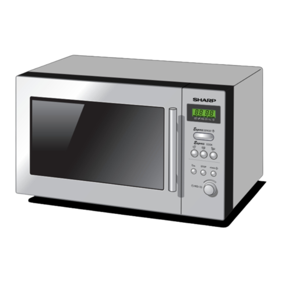
Page 8: Appearance View
Stir Turn over Weight Portion Indicator Microwave power level Cooking in progress indicator 1. DIGITAL DISPLAY 2. EXPRESS DEFROST buttons 3. EXPRESS COOK buttons POWER LEVEL button STOP button +1 MIN/STARTbutton TIME/WEIGHT/PORTION knob R-24ST/R-2B34 - 8... -
Page 9: Operation Sequence
SWITCH CONTACT COOKING (NO COOKING) Monitor switch COM-NC Open Closed Monitored latch switch COM-NO Closed Open The circuits to the power transformer, fan motor and turntable motor are cut off when the monitored latch switch is opened. R-24ST/R-2B34 - 9... -
Page 10: Function Of Important Components
2. When the oven door is opened, the contacts (COM - NO) must be opened. CAUTION: BEFORE REPLACING A BLOWN FUSE (F1) TEST THE MONITORED LATCH SWITCH (SW1) AND MONITOR SWITCH (SW2) FOR PROPER OPERATION. (REFER CHAPTER "TEST PROCEDURE".) R-24ST/R-2B34 - 10... -
Page 11: Troubleshooting Guide
800w cooking condition. Oven goes into cook cycle but shuts down before end of cooking cycle. Oven stops as soon as the oven is started. motor, oven lamp turntable motor do not operate at the same time. R-24ST/R-2B34 - 11... -
Page 12: Test Procedure
3. Place the load on the centre of the shelf. 4. Operate the microwave oven at HIGH for the temperature of the water rises by a value ∆ T of (10 ± 2) K. 5. Stir the water to equalize temperature throughout the vessel. R-24ST/R-2B34 - 12... - Page 13 Secondary winding ..140 ohms approximately c. Filament winding ... less than 1 ohm If the reading obtained are not as stated above, then the power transformer is probably faulty and should be replaced. CARRY OUT 4R CHECKS R-24ST/R-2B34 - 13...
- Page 14 Plunger Operation COM to NO COM to NC Normally open terminal Released Open circuit Short circuit Normally close terminal Depressed Short circuit Open Circuit If incorrect readings are obtained, or replace the switch. CARRY OUT 4R CHECKS. R-24ST/R-2B34 - 14...
- Page 15 INDICATION OF OHMMETER Between N and L Open circuit Between terminal N and WHITE Short circuit Between terminal L and RED Short circuit If incorrect readings are obtained, replace the noise filter unit. CARRY OUT 4R CHECKS R-24ST/R-2B34 - 15...
- Page 16 The figure of all digits flicker. h) When touching a tact switch, the control unit does not respond. 4. Other possible problems caused by defective control unit. a) Buzzer does not sound or continues to sound. b) Cooking is not possible. R-24ST/R-2B34 - 16...
- Page 17 *Insert the coil RCILF2003YAZZ between "c" and "d". NOTE: *At the time of making these repairs, make a visual inspection of the varistor. Check for burned damage. If any ab- normal condition is detected, replace the defective parts. (J1) CN - A R-24ST/R-2B34 - 17...
-
Page 18: Control Panel Assembly
This circuit generates voltage necessary in the control unit from the AC line voltage. In addition, the synchronizing signal is available in order to compose a basic standard time in the clock circuit. Symbol Voltage Application LSI(IC1) R-24ST/R-2B34 - 18... - Page 19 When the encoder is turned, the contacts of encoder make pulse signals. And pulse signals are input into R73. INT2 Signal synchronized with commercial power source frequency. H : +5V This is the basic timing for time processing of LSI. L : 0V 20.0 msec R-24ST/R-2B34 - 19...
- Page 20 Connected to LCD (Pin No. 1) COM2 Common data signal: COM2. Connected to LCD (Pin No. 2) COM3 Common data signal: COM1. Connected to LCD (Pin No. 3) COM4 Terminal not used. Power source voltage input terminal. Connected to VC. R-24ST/R-2B34 - 20...
- Page 21 A. On some models, the power supply cord between the touch control panel and the oven is so short that the two can't be separated. For those models, check and repair all the controls (sensor-related ones included) of the touch control R-24ST/R-2B34 - 21...
-
Page 22: Component Replacement And Adjustment Procedure
2. Disconnect the filament leads of the power transformer base plate. from high voltage capacitor and the magnetron. 5. Remove the transformer. 3. Disconnect the H.V. wire A from the power transformer. 6. Now, the power transformer is free. R-24ST/R-2B34 - 22... - Page 23 5. Turntable motor is now free. 3. Where the corners have been snipped off bent corner 6. After repplacement use the one (1) screw to fit the areas flat. No sharp edge must be evident after removal turntable motor cover. of turntable motor cover.
- Page 24 Power supply cord back plate OVEN CAVITY Green / Yellow BACK PLATE Wire Brown Wire Chassis support Blue Wire SQUARE HOLE Noise filter Figure C-1 (a) Replacement of Power Supply Cord Figure C-1(b). Replacement of Power Supply Cord R-24ST/R-2B34 - 24...
- Page 25 0.5mm. 2. The monitored latch switch and stop switch interrupt the Figure C-3. Latch Switch Adjustments circuit before the door can be opened. 3. The monitor switch contacts (COM-NC) close when the door is opened. R-24ST/R-2B34 - 25...
- Page 26 (Refer to chapter “Test Procedures”.). (B) An approved microwave survey meter should be used to assure compliance with proper microwave Finger tab radiation emission limitation standards. Figure C-6. Inner Sealer Film R-24ST/R-2B34 - 26...
-
Page 27: Microwave Measurement
6. The microwave radiation emission should be measured standard for microwave ovens must be used for testing. at any point of 5cm or more from the external surface of the oven. mW cm mW cm Microwave leakage measurement at 5 cm distance R-24ST/R-2B34 - 27... -
Page 28: Test Data At A Glance/Wiring/Rewiring
3. Wires are connected correctly as per pictorial diagram. voltage capacitor and high voltage rectifier). 4. No wire leads are trapped by the outer wrap. b) Parts that become hot. (Heating elements, oven lamp, oven cavity magnetron and high voltage transformer). R-24ST/R-2B34 - 28... -
Page 29: Schematic Diagrams
WITH 150˚C THERMOSTAT F1: FUSE IN PRIMARY WINDING (F8A) COM. N.O. RY-2 RY-1 H.V. CAPACITOR 0.91µF/ AC2100V N.O. SW3: STOP SWITCH N.C. COM. SW1: MONITORED SW2: MONITOR LATCH SWITCH SWITCH N.O. Figure 0-2 Oven Schematic-ON Condition, Open Closed. R-24ST/R-2B34 - 29... -
Page 30: Pictorial Diagram
PICTORIAL DIAGRAM R-24ST/R-2B34 - 30... -
Page 31: Control Panel Circuit Diagram
CONTROL PANEL CIRCUIT DIAGRAM R-24ST/R-2B34 - 31... -
Page 32: Tact Switch Diagram
TACT SWITCH UNIT CIRCUIT DIAGRAM CN-C Figure S-3. Tact Switch Unit Circuit Diagram R-24ST/R-2B34 - 32... -
Page 33: Printed Wiring Board Diagram
PRINTED WIRING BOARD DIAGRAM LED1 LED2 LED3 CN - C (J6) (J4) (J2) (J3) (J5) (J7) (R60) (R61) (R62) (R63) (WH-1) ZD71 (J1) CN - A Figure S-4. Printed Wiring Board R-24ST/R-2B34 - 33... -
Page 34: Printed Wiring Board Of Tact Switch Diagram
PRINTED WIRING BOARD DIAGRAM OF SWITCH UNIT Figure S-5. Printed Wiring Board Of Tact Switch Unit R-24ST/R-2B34 - 34... -
Page 35: Parts List
10k ohm 1/4W VRD-B12EF822J Resistor 8.2k ohm 1/4W VRD-B12EF332J Resistor 3.3k ohm 1/4W VRD-B12EF153J Resistor 15k ohm 1/4W VRD-B12HF152J Resistor 1.5k ohm 1/2W VRD-B12EF102J Resistor 1.0k ohm 1/4W VRD-B12EF153J Resistor 15k ohm 1/4W VRN-B12EK103F Resistor 10k ohm 1/4W R-24ST/R-2B34 - 35... - Page 36 Zener diode (HZ4C-3) ZD70-71 VHEHZ7C2///-1 Zener diode (HZ7C2) 3- 2 FPWBFA053URK0 Switch unit assembly 3- 3 HPNLCR022URF0 Control panel frame (R-24ST R-2B34(ST/AL/K) 3- 3 HPNLCW072URF0 Control panel frame (R-2B34(W) 3- 4 GMADIA032URR0 Display window printed (All) 3- 5 JBTN-S009URT0 Select button painted (R-24ST R-2B34(ST/AL/K)
- Page 37 Door panel assembly[All models] FWAKPW029URK0 Door frame assy R-2B34(W) FWAKPK003URK0 Door frame assy R-2B34(K) FWAKPA038URK0 Door frame assy R-2B34(AL) FWAKPS017URK0 Door frame assy R-24ST /R-2B34(ST) GWAKPR013URF0 Door frame (moulded) PGLSPA013URE0 Outer door glass[All models] LSTPPA013URF0 Latch head[All models] MSPRTA141WRE0 Latch spring[All models]...
-
Page 38: Exploded Diagram Of Oven Parts
EXPLODED DIAGRAM OF OVEN PARTS 4-10 7-10 4-11 4-12 NOTE: In the event of removing the turntable motor cover this part should be refitted using screw connection: LX-CZA030WRE0 (7-11) R-24ST/R-2B34 - 38... -
Page 39: Control Panel/Door Parts
3-1D 3 - 9 3 - 3 3 - 8 3 - 5 3 - 8 3 - 4 3 - 7 3 - 10 3 - 2 3 - 6 DOOR PARTS 5-13 5-11 5-12 5-10 R-24ST/R-2B34 - 39... -
Page 40: Miscellaneous/Packing & Accessories
MISCELLANEOUS/PACKING AND ACCESSORIES MISCELLANEOUS Actual wire harness may be different from illustration. COPYRIGHT C 2001 BY SHARP CORPORATION ALL RIGHT RESERVED. No part of this publication may be reproduced, stored in a retrieval system, or transmitted in any form or by any means, electronic, mechanical, photocopying, recording, or otherwise, without prior written permission of the publisher.