
Related Manuals for Samsung SSA-R1003


Summary of Contents for Samsung SSA-R1003
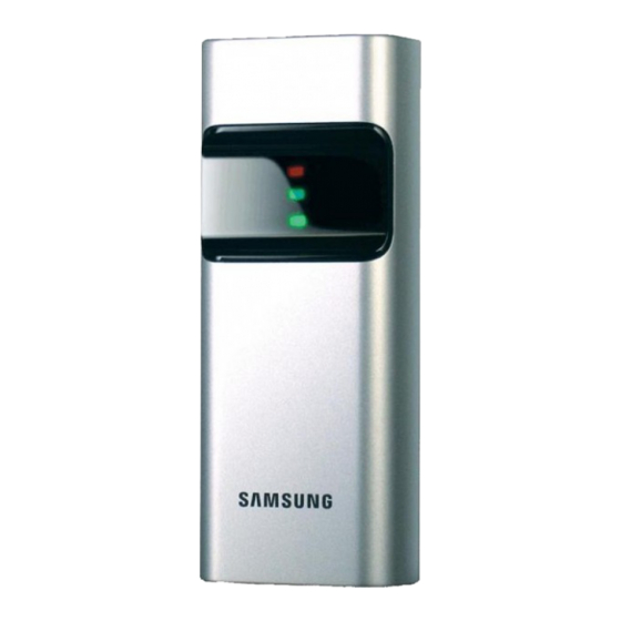
- Page 1 SSA-R1003 SSA-R1103 RFID Reader user manual imagine the possibilities Thank you for purchasing this Samsung product. To receive more complete service, please visit our website. www.samsungsecurity.com...
- Page 2 If this product fails to operate normally, contact the nearest service center. Never disassemble or modify this product in any way. (SAMSUNG is not liable for problems caused by unauthorized modifi cations or attempted repair.) . When cleaning, do not spray water directly onto parts of the product. Doing so may cause fi re or electric shock.
- Page 3 Apparatus shall not be exposed to dripping or splashing and no objects fi lled with liquids, such as vases, shall be placed on the apparatus. The Mains plug is used as a disconnect device and shall stay readily operable at any time. FCC Statement Caution : Any changes or modifi...
-
Page 4: Table Of Contents
contents PRODUCT INTRODUCTION Features What’s included At a Glance Cable Color Scheme Cable Selection INSTALLATION AND EXTERNAL Installation Precautions on installation CONNECTION External Connection Basic Operations INITIALIZATION WIEGAND Output OUTPUT FORMAT RS-232 Output TROUBLESHOOTING Troubleshooting PRODUCT SPECIFICATIONS Product Specifi cations contents... - Page 5 ◆ Reverse Polarity Protection ◆ Weatherproof WHAT’S INCLUDED Check if the following items are included in the product package. What’s included in SSA-R1003 3.5 x 40 screws (x2) Bezel of SSA-R1003 READER Module 3.5 x 25 screws (x2) Quick Guide...
- Page 6 product introduction AT A GLANCE Front/Rear Displays the system operation status using red and green indicators. Buzzer Piezo buzzer. Connection Cable Used to connect to the power or I/O cable. Fixing Hole Fixing hole for wall-mounting. product introduction...
- Page 7 CABLE COLOR SCHEME Item Cable Color Signal Line Description DC +12V DC +12V supplied Power Black Earth-grounding for power Blue Buzzer Control BUZZER Control Input Port Input Yellow LED Control LED Control Input Port Green Out Wiegand 0 Wiegand Data 0 Output Port Output White Out Wiegand 1...
-
Page 8: Installation
installation and external connection INSTALLATION - Inserted in the doorframe / attached to the wall Two 6-32 or M3 holes are 3.3” (8.38 cm) away from each other vertically; between the two exists one 1/2” hole through which the reader cables are arranged. The midway hole is located 1.7” (4.31cm) down from the upper hole. -
Page 9: Precautions On Installation
PRECAUTIONS ON INSTALLATION If installing on a metal wall If you install the reader on a metal wall, the read range may be reduced. To avoid this problem, it is recommended to insert the spacer between the metal wall and the reader as shown below. Metal Wall Spacer... -
Page 10: External Connection
EXTERNAL CONNECTION Wiring Diagram SSA-R1003/SSA-R1103 Buzzer Control In RS-232(TX) Brown Blue LED Control In Yellow CONTROLLER Wiegand Data 0 Out Green RS-232(GND) Black Wiegand Data 1 Out White Black DC +12V POWER Item Cable Color Connect the DC+12V to the red line. -
Page 11: Basic Operations
initialization BASIC OPERATIONS Initial State (when the power is supplied) When you apply power to the reader, it will sound a beep before entering Standby with the red indicator turned on . Using the card Present the card to the reader until you hear a beep and the red indicator turns green. When the reader has transferred the card data to the controller, it returns to Standby with the red indicator turned on and waits for reading the next card. -
Page 12: Wiegand Output
output format WIEGAND OUTPUT Timing Diagram 100us DATA-0 DATA-1 *n : 26 LOGIC Data Type • Bit 1 : Even Parity (bit 2 ~ bit 13) • Bit 2 ~ 9 : Facility Code (000 ~ 255) • Bit 10 ~ 25 : ID Number (00000 ~ 65,535) •... -
Page 13: Rs-232 Output
RS-232 OUTPUT Output Waveform +15V Space(=0) Indeterminate Region Mark(=1) 8 Data Bits -15V 2 Stop Bits Start Bit Data packet corresponding to ASCII character ‘A’ Data Type Start (0X02H) Data (8 Char) End (0x03H) START(0X02H) DATA (1~8 Char) END (0x03H) ... -
Page 14: Troubleshooting
troubleshooting TROUBLESHOOTING If the product does not function properly, please see the below for trouble shooting. PROBLEM SOLUTION My card is not read properly. Check the rated voltage specifi ed in the user manual and the catalog. Check if this is a 125KHz proximity (EM format) card. 3) If the problem persists, contact the nearest customer service for your assistance. -
Page 15: Product Specifi Cations
PRODUCT SPECIFICATIONS Item SSA-R1003 SSA-R1103 Power / Current DC 12V / Max.40mA Reading Time (Card) 30ms Input Port 2ea : External LED Control, External Buzzer Control Output Port 26bit Wiegand LED Indicator 2 Color LED (Red and Green) - Page 16 TEL : +82-70-7147-8740~60 FAX : +82-31-8018-3745 SAMSUNG TECHWIN AMERICA Inc. SAMSUNG TECHWIN EUROPE LTD. 1480 Charles Willard St, Carson, CA 90746, UNITED STATES Samsung House, 1000 Hillswood Drive, Hillswood Business Tol Free : +1-877-213-1222 FAX : +1-310-632-2195 Park Chertsey, Surrey, UNITED KINGDOM KT16 OPS www.samsungcctvusa.com TEL : +44-1932-45-5300 FAX : +44-1932-45-5325 www.samsungsecurity.com...