Table of Contents
Quick Links
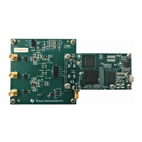
This user's guide describes the characteristics, operation and use of the ADS7042-EVM performance
demonstration kit (PDK). This kit is an evaluation platform for the ADS7042 low power, 12-bit, successive
approximation register (SAR) analog-to-digital converters (ADCs) that supports single-ended analog
inputs.
This EVM eases the evaluation of the ADS7042 device with hardware and software for computer
connectivity through universal serial bus (USB). This user's guide includes complete circuit descriptions,
schematic diagrams, and a bill of materials.
The following related documents are available through the Texas Instruments web site at
http://www.ti.com.
......................................................................................................................
1
Overview
1.1
ADS7042 EVM Features
1.2
ADS7042EVM-PDK Features
2
EVM Analog Interface
3
Power Supplies
4
Digital Interface
5
ADS7042EVM-PDK Initial Setup
5.1
Default Jumper Settings
5.2
Software Installation
6
ADS7042EVM-PDK Kit Operation
6.1
About the SCC Controller Board
6.2
Loading the ADS7042EVM Software
SBAU234A – October 2014 – Revised November 2014
Submit Documentation Feedback
Table 1. Related Documentation
Device
OPA835
TPS79101
REG71055
TPS62080
TPS3836K33
...........................................................................................
.....................................................................................
.......................................................................................................
..............................................................................................................
..............................................................................................................
..........................................................................................
...........................................................................................
................................................................................................
.......................................................................................
................................................................................
Copyright © 2014, Texas Instruments Incorporated
SBAU234A – October 2014 – Revised November 2014
ADS7042EVM-PDK
Literature Number
SLOS713
SLVS325
SBAS221
SLVSAE8
SGLS322
Contents
...........................................................................
User's Guide
3
3
3
3
4
5
5
5
5
11
11
11
1
ADS7042EVM-PDK
Table of Contents

Related Manuals for Texas Instruments ADS7042EVM-PDK


Summary of Contents for Texas Instruments ADS7042EVM-PDK
-
Page 1: Related Documentation
This EVM eases the evaluation of the ADS7042 device with hardware and software for computer connectivity through universal serial bus (USB). This user's guide includes complete circuit descriptions, schematic diagrams, and a bill of materials. The following related documents are available through the Texas Instruments web site at http://www.ti.com. Table 1. Related Documentation... -
Page 2: Table Of Contents
Related Documentation ....................Analog Input Connections ..................... AVDD Voltage Settings ..................... AVDD Voltage Settings ..................... Default Jumper Configurations ................... ADS7042EVM Bill of Materials ADS7042EVM-PDK SBAU234A – October 2014 – Revised November 2014 Submit Documentation Feedback Copyright © 2014, Texas Instruments Incorporated... -
Page 3: Ads7042Evm Analog Input Connections
Overview The ADS7042EVM-PDK is a platform for evaluation of the ADS7042 ADC. The evaluation kit combines the ADS7042EVM board with a Simple Capture Card controller board. This controller card consists of a TI Sitara embedded microcontroller (AM3352) and a field-programmable gate array (FPGA). It provides an interface from the EVM to the computer through a universal serial bus (USB) port. -
Page 4: Analog Input Connections
1.8V to 3.6V. The DVDD operates from 1.65 V to 3.6 V, independent of the AVDD supply. The analog portion of the ADS7042EVM-PDK operates from a 5-V supply. The ADS7042EVM-PDK is configured to use the onboard regulated analog 5-V supply that in turn generates an AVDD analog supply using the low-noise TPS79101 LDO. -
Page 5: Ads7042Evm Default Jumper Settings
The ADS7042EVM has clearly marked test points for all the SPI signals to allow observation of the interface signals using an oscilloscope. ADS7042EVM-PDK Initial Setup This section presents the steps required to set up the ADS7042EVM-PDK kit before operation. Default Jumper Settings A silkscreen plot detailing the default jumper settings is shown in... -
Page 6: Bottom View Of Simple Capture Card With Microsd Memory Card Installed
Install the microSD Memory Cards on the Simple Capture Card Controller Board As mentioned in the previous section, the ADS7042EVM-PDK includes two microSD memory cards. One is installed on the microSD socket (P6) at the back of the Simple Capture Card as shown in Figure 3. -
Page 7: Connecting Ads7042Evm Board To Simple Capture Card
Capture Card to boot properly. In addition to this the microSD card on the EVM contain Simple Capture Card firmware files (app and MLO files) and the ADS7042EVM-PDK software installation files inside the ADS7042 EVM V#.#.# folder. -
Page 8: Welcome Screen And Destination Directory Screens
Step 8. A progress bar appears; this step takes a few minutes. Step 9. The progress bar is followed by an Installation Complete notice. ADS7042EVM-PDK SBAU234A – October 2014 – Revised November 2014 Submit Documentation Feedback Copyright © 2014, Texas Instruments Incorporated... -
Page 9: Progress Bar And Installation Complete Screens
Figure 10. Windows 7 Driver Installation Warning NOTE: Driver installation prompts do not appear if the Simple Capture Card driver has been installed on your system previously. SBAU234A – October 2014 – Revised November 2014 ADS7042EVM-PDK Submit Documentation Feedback Copyright © 2014, Texas Instruments Incorporated... -
Page 10: Simple Capture Card Driver Installation
Step 2. A computer restart may be required to finish the software installation. If prompted, restart the PC to complete the installation. Figure 11. Simple Capture Card Driver Installation Figure 12. Simple Capture Card Driver Completion ADS7042EVM-PDK SBAU234A – October 2014 – Revised November 2014 Submit Documentation Feedback Copyright © 2014, Texas Instruments Incorporated... -
Page 11: Gui Display Prompt
Step 1. Make sure the EVM kit is configured and powered up as explained in Section Step 2. Start the ADS7042 EVM software. Go to Start → All Programs →Texas Instruments → ADS7042 EVM and click ADS7042 EVM to run the software. -
Page 12: Capturing Data With The Ads7042-Pdk
GUI screen; a menu with different GUI pages appears. Click on the Data Capture option in the menu as shown in Figure Figure 14. Open the Data Capture Page on the GUI ADS7042EVM-PDK SBAU234A – October 2014 – Revised November 2014 Submit Documentation Feedback Copyright © 2014, Texas Instruments Incorporated... -
Page 13: Data Capture Page
SCLK: This control sets the clock frequency used by the SPI interface to capture data. By configuring the SCLK frequency, the sampling rate of the ADS7042 is set. The ADS7042EVM-PDK software supports SCLK frequencies of 3.2 MHz to 16 MHz. In case the input in this field is beyond the capability of the device, it will be adjusted to the nearest value that can be supported. -
Page 14: Fft Analysis
Any harmonic signal greater than this number is treated as noise in the performance calculations. The typical value used in this analysis is 9 as per the ADS7042 datasheet (SBAS608). ADS7042EVM-PDK SBAU234A – October 2014 – Revised November 2014 Submit Documentation Feedback Copyright © 2014, Texas Instruments Incorporated... -
Page 15: Histogram Analysis
The Sigma indicator displays standard deviation of the data set. This value is equivalent to the RMS noise of the signal when analyzing a dc data set. SBAU234A – October 2014 – Revised November 2014 ADS7042EVM-PDK Submit Documentation Feedback Copyright © 2014, Texas Instruments Incorporated... -
Page 16: Offset Calibration
This computed offset will remain fixed, unless the device is reset or there is a significant change in operating temperature or analog supply voltage. ADS7042EVM-PDK SBAU234A – October 2014 – Revised November 2014 Submit Documentation Feedback Copyright © 2014, Texas Instruments Incorporated... -
Page 17: Estimated Current Consumption
Troubleshooting Although the ADS7042EVM GUI rarely stops responding while the ADS7042EVM-PDK is connected, in case this does happen, unplug the USB cable from the EVM, unload the ADS7042EVM-PDK software, reconnect the ADS7042EVM-PDK to the PC and reload the ADS7042EVM software. -
Page 18: Bill Of Materials, Pcb Layout, And Schematics
1.2~5.5V,Ultralow Noise High PSRR Fast RF 100mA LDO Texas Instruments TPS79101DBVREP Linear Regulator IC, Low-power SAR ADC, RUG-8, 1.5x1.5x0.4mm Texas Instruments ADS7042IRUG ADS7042EVM-PDK SBAU234A – October 2014 – Revised November 2014 Submit Documentation Feedback Copyright © 2014, Texas Instruments Incorporated... - Page 19 Texas Instruments TPS62080DSG Mode, SON-8 IC, Nanopower Supervisory Circuits, SOT23-5 Texas Instruments TPS3836K33DBVR for J2 SanDisk microSDHC™ Card - 4GB SANDISK SDSDQ-004G-A11M SBAU234A – October 2014 – Revised November 2014 ADS7042EVM-PDK Submit Documentation Feedback Copyright © 2014, Texas Instruments Incorporated...
-
Page 20: Pcb Layout
ADS7042EVM PCBs. Figure 20. ADS7042EVM PCB: Top Layer (L1) Figure 21. ADS7042EVM PCB: GND Layer (L2) ADS7042EVM-PDK SBAU234A – October 2014 – Revised November 2014 Submit Documentation Feedback Copyright © 2014, Texas Instruments Incorporated... -
Page 21: Ads7042Evm Pcb: Power Layer (L3)
Bill of Materials, PCB Layout, and Schematics www.ti.com Figure 22. ADS7042EVM PCB: Power Layer (L3) Figure 23. ADS7042EVM PCB: Bottom Layer (L4) SBAU234A – October 2014 – Revised November 2014 ADS7042EVM-PDK Submit Documentation Feedback Copyright © 2014, Texas Instruments Incorporated... -
Page 22: Schematics
Changed wording in first paragraph after ADS7042 EVM Analog Input Connections image. NOTE: Page numbers for previous revisions may differ from page numbers in the current version. Revision History SBAU234A – October 2014 – Revised November 2014 Submit Documentation Feedback Copyright © 2014, Texas Instruments Incorporated... - Page 23 0 (UN) 49.9 0 (UN) +3.3VD OPA+ 0.1µF AVDD AVDD 0.1µF SCLK DVDD SCLK DVDD OPA835IDBV AIN+ DVDD AINP VCCA VCCB 1µF 1µF 49.9 25.5 25.5 AIN- DVDD AINM OPA+ 10.0k 0.0015uF ADS7042IRUG 0.1µF SN74AVCH1T45DBVR 25.5 1.0M 0 (UN) 0.0015uF SMA-J-P-X-ST-EM1 OPA- 49.9...
- Page 24 STANDARD TERMS AND CONDITIONS FOR EVALUATION MODULES Delivery: TI delivers TI evaluation boards, kits, or modules, including any accompanying demonstration software, components, or documentation (collectively, an “EVM” or “EVMs”) to the User (“User”) in accordance with the terms and conditions set forth herein. Acceptance of the EVM is expressly subject to the following terms and conditions.
- Page 25 FCC Interference Statement for Class B EVM devices NOTE: This equipment has been tested and found to comply with the limits for a Class B digital device, pursuant to part 15 of the FCC Rules. These limits are designed to provide reasonable protection against harmful interference in a residential installation.
- Page 26 【無線電波を送信する製品の開発キットをお使いになる際の注意事項】 本開発キットは技術基準適合証明を受けておりません。 本製品のご使用に際しては、電波法遵守のため、以下のいずれかの措置を取っていただく必要がありますのでご注意ください。 1. 電波法施行規則第6条第1項第1号に基づく平成18年3月28日総務省告示第173号で定められた電波暗室等の試験設備でご使用 いただく。 2. 実験局の免許を取得後ご使用いただく。 3. 技術基準適合証明を取得後ご使用いただく。 なお、本製品は、上記の「ご使用にあたっての注意」を譲渡先、移転先に通知しない限り、譲渡、移転できないものとします。 上記を遵守頂けない場合は、電波法の罰則が適用される可能性があることをご留意ください。 日本テキサス・インスツルメンツ株式会社 東京都新宿区西新宿6丁目24番1号 西新宿三井ビル 3.3.3 Notice for EVMs for Power Line Communication: Please see http://www.tij.co.jp/lsds/ti_ja/general/eStore/notice_02.page 電力線搬送波通信についての開発キットをお使いになる際の注意事項については、次のところをご覧くださ い。http://www.tij.co.jp/lsds/ti_ja/general/eStore/notice_02.page SPACER EVM Use Restrictions and Warnings: 4.1 EVMS ARE NOT FOR USE IN FUNCTIONAL SAFETY AND/OR SAFETY CRITICAL EVALUATIONS, INCLUDING BUT NOT LIMITED TO EVALUATIONS OF LIFE SUPPORT APPLICATIONS.
- Page 27 Notwithstanding the foregoing, any judgment may be enforced in any United States or foreign court, and TI may seek injunctive relief in any United States or foreign court. Mailing Address: Texas Instruments, Post Office Box 655303, Dallas, Texas 75265 Copyright © 2014, Texas Instruments Incorporated...
- Page 28 IMPORTANT NOTICE Texas Instruments Incorporated and its subsidiaries (TI) reserve the right to make corrections, enhancements, improvements and other changes to its semiconductor products and services per JESD46, latest issue, and to discontinue any product or service per JESD48, latest issue.
- Page 29 Mouser Electronics Authorized Distributor Click to View Pricing, Inventory, Delivery & Lifecycle Information: Texas Instruments ADS7042EVM-PDK...