Quick Links
Siemens Industry, Inc.
Kit P/N 16300-1355
Kit P/N TGX:16300-1438
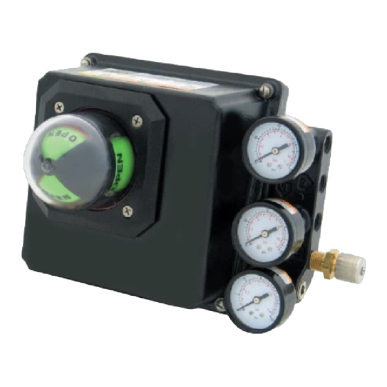
Use this kit to convert a Model 760P pneumatic input valve positioner to a Model 760E that accepts a 4-20 mA input
signal. This kit is also used to replace a failed I/P transducer in a 760E. A copy of SD760, the Series 760 Installation
and Service Instruction, should be available for reference. Refer to SD760 for non-hazardous and hazardous area
installation requirements and for environmental specifications. When installing or servicing in a hazardous area,
refer to Siemens Control Drawing 15032-7602, supplied in SD760.
•
Remove power from all wires and terminals before working on
equipment.
•
In potentially hazardous atmosphere, remove power from equipment
before connecting or disconnecting power, signal, or other circuit.
•
Observe all pertinent regulations regarding installation in a hazardous
area.
Kit Parts List
Description
I/P Transducer
I/P Manifold
O-Ring
Wire Clamp
Clamping Plate
10-32 x 2-1/4 Binding Head Screw
Installation
Perform the following steps to install the parts in this kit. Note the following when a step is prefaced with a 760
model:
•
"760P" - Perform this step when converting a 760P to a 760E.
•
"760E" - Perform this step when replacing an I/P transducer in a 760E.
1.
Remove all electrical power and process signals from the positioner.
2.
Remove supply air from the positioner.
3.
Remove the cover by loosening a screw at each corner of the cover and lifting the cover from the positioner.
KIT INSTALLATION INSTRUCTION
ValvePAC™ Series 760 Valve Positioner
I/P Transducer Kit
Electrical shock hazard
Explosion hazard
Can cause death, serious injury or property damage
Quantity
1
1
4
1
1
1
WARNING
Description
10-32 x 3/8 Slotted Hex Head Screw
8-32 x 1/4 Binding Head Screw
8-32 x .375 SL/TX PN TR
#8 External Tooth Lockwasher
Terminal Washer
Pipe Plug
15900-378
Rev. 8
November 2021
Quantity
1
1
1
1
1
1

Related Manuals for Siemens ValvePAC Series


Summary of Contents for Siemens ValvePAC Series
- Page 1 Service Instruction, should be available for reference. Refer to SD760 for non-hazardous and hazardous area installation requirements and for environmental specifications. When installing or servicing in a hazardous area, refer to Siemens Control Drawing 15032-7602, supplied in SD760. WARNING...
- Page 2 I/P Transducer Kit 15900-378 Remove installed parts. Refer to the figure on page 3 as needed. • 760P: Remove the sealing plate screw, sealing plate and two O-rings (the O-rings may adhere to the back of the sealing plate). • 760E: Disconnect two signal input wires from the I/P transducer.
- Page 3 Customer/Product Support For support and the location of your local Siemens representative, refer to the table below for the URL of the Process Instrumentation (PI) portion of the Siemens public Internet site. Once at the site, click Support in the right column and then Product Support.
- Page 4 Industry, Inc. or other supplier companies whose use by third parties for their own purposes could violate the rights of the owners. Siemens Industry, Inc. assumes no liability for errors or omissions in this document or for the application and use of information in this document. The information herein is subject to change without notice.