
Related Manuals for Emerson Rosemount 2051G


Summary of Contents for Emerson Rosemount 2051G
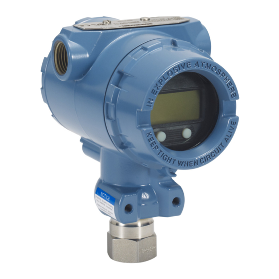
- Page 1 Quick Start Guide 00825-0700-4101, Rev AD May 2019 ™ Rosemount 2051G Pressure Transmitter ® with 4-20 mA HART Protocol (Revision 5 and 7)
-
Page 2: Table Of Contents
Quick Start Guide May 2019 Contents About this guide...........................3 System readiness......................... 5 Mount the transmitter........................6 Set the switches........................... 9 Connect the wiring and power up....................10 Verify transmitter configuration....................13 Trim the transmitter........................19 Safety instrumented systems..................... 22 Product certifications......................... 23 Emerson.com/Rosemount... -
Page 3: About This Guide
™ This guide provides basic guidelines for Rosemount 2051G Transmitters. It does not provide instructions for configuration, diagnostics, maintenance, service, troubleshooting, Explosion-proof, Flameproof, or intrinsically safe (I.S.) installations. See the Rosemount 2051G Reference Manual for more information. WARNING Explosions could result in death or serious injury. - Page 4 Physical security is an important part of any security program and fundamental to protecting your system. Restrict physical access by unauthorized personnel to protect end users’ assets. This is true for all systems used within the facility. Emerson.com/Rosemount...
-
Page 5: System Readiness
Procedure ™ 1. Verify the latest Device Driver (DD/DTM ) is loaded on your systems to ensure proper communications. 2. Reference Emerson.com FieldCommGroup.org for the latest DD. 3. Select desired product and download the DD. a) Reference Table 2-1 for the correct DD. -
Page 6: Mount The Transmitter
Figure 3-2: Panel and Pipe Mounting Panel mount Pipe mount Liquid flow applications Procedure 1. Place taps to the side of the line. 2. Mount beside or below the taps. 3. Mount the transmitter so the drain/vent valves are oriented upward. Emerson.com/Rosemount... - Page 7 May 2019 Quick Start Guide Gas flow applications Procedure 1. Place taps in the top or side of the line. 2. Mount level or above the taps. Steam flow applications Procedure 1. Place taps to the side of the line. 2.
- Page 8 Keep the vent path free of any obstruction, including but not limited to paint, dust, and lubrication by mounting the transmitter so the contaminants can drain away. Figure 3-3: Gage Low Side Pressure Port Low side pressure port (atmospheric reference) Emerson.com/Rosemount...
-
Page 9: Set The Switches
May 2019 Quick Start Guide Set the switches Set alarm and security switch configuration before installation as shown in Figure 4-1. • The alarm switch sets the analog output alarm to high or low. Default alarm is high. • The security switch allows ( ) or prevents ( ) any configuration of the transmitter. -
Page 10: Connect The Wiring And Power Up
Do not connect the powered signal wiring to the test terminals. Power could damage the test diode in the terminal block. Use the following steps to wire the transmitter: Procedure 1. Remove the housing cover on the FIELD TERMINALS side. Emerson.com/Rosemount... - Page 11 May 2019 Quick Start Guide 2. Connect the leads as shown in Figure 5-1. 3. Tighten the terminal screws to ensure full contact with the terminal block screw and washer. When using a direct wiring method, wrap wire clockwise to ensure it is in place when tightening the terminal block screw.
- Page 12 (internal or external). If the transmitter is currently not wired for power up and communication, follow Connect the wiring and power up. When the transmitter is properly wired, refer to Figure 5-2 for internal and external transient grounding locations. Emerson.com/Rosemount...
-
Page 13: Verify Transmitter Configuration
Refer to Table 6-2 and the appropriate column based on your Field Revision and HART Revision for Fast Key sequences. Note Emerson recommends installing the latest DD to access the complete functionality. Visit Emerson.com or FieldCommGroup.org. Figure 6-1: Traditional Interface... - Page 14 Digital To Analog Trim (4– 1,2,3,2,1 20 mA Output) Disable Local Span/Zero 1,4,4,1,7 Adjustment Field Device Info 1,4,4,1 Keypad Input 1,2,3,1,1 Loop Test 1,2,2 Lower Range Value Lower Sensor Trim 1,2,3,3,2 Message 1,3,4,3 Meter Type 1,3,6,1 Number of Requested 1,4,3,3,2 Emerson.com/Rosemount...
- Page 15 May 2019 Quick Start Guide Table 6-1: Traditional Interface Fast Keys (continued) Function Fast Key sequence Output Trim 1,2,3,2 Percent Range 1,1,2 Poll Address 1,4,3,3,1 ✓ Range Values 1,3,3 Rerange 1,2,3,1 Scaled D/A Trim (4–20 mA 1,2,3,2,2 Self Test (Transmitter) 1,2,1,1 Sensor Info 1,4,4,2...
- Page 16 Verifying configuration with LOI The optional LOI can be used for commissioning the device. The LOI is a two- button design with internal and external buttons. The internal buttons are located on the display of the transmitter, while the external buttons are Emerson.com/Rosemount...
- Page 17 May 2019 Quick Start Guide located underneath the top metal tag. To activate the LOI, push any button. LOI button functionality is shown on the bottom corners of the display. See Table 6-3 Figure 6-4 for button operation and menu information. Figure 6-3: Internal and External LOI Buttons A.
- Page 18 Generic Menu: Procedure Manual Setup → Device Information → Identification → Message a) To change to HART Revision 5, Enter: “HART5” in the Message field. b) To change to HART Revision 7, Enter: “HART7” in the Message field. Emerson.com/Rosemount...
-
Page 19: Trim The Transmitter
May 2019 Quick Start Guide Trim the transmitter Devices are calibrated by the factory. Once installed, it is recommended to perform a zero trim on gage and absolute transmitters to eliminate error due to mounting position or static pressure effects. A zero trim can be performed using either a Field Communicator or configuration buttons. - Page 20 Select Rerange to perform an analog zero trim. b) Select Zero Trim to perform a digital zero trim. 7.3.2 Perform trim with analog zero and span (option D4) Procedure 1. Set the transmitter pressure. Emerson.com/Rosemount...
- Page 21 May 2019 Quick Start Guide 2. Press and hold the zero button for two seconds to perform an analog zero trim. 7.3.3 Perform trim with digital zero (option DZ) Procedure 1. Set the transmitter pressure. 2. Press and hold the zero button for two seconds to perform a digital zero trim.
-
Page 22: Safety Instrumented Systems
Quick Start Guide May 2019 Safety instrumented systems ™ For safety certified installations, refer to the Rosemount 2051G Reference Manual for installation procedure and system requirements. Emerson.com/Rosemount... -
Page 23: Product Certifications
A copy of the EU Declaration of Conformity can be found at the end of the Quick Start Guide. The most recent revision of the EU Declaration of Conformity can be found at Emerson.com/Rosemount. North America E5 USA Explosionproof (XP) and Dust-Ignitionproof (DIP) - Page 24 2. Flameproof joints are not intended for repair. 3. Non-standard paint options may cause risk from electrostatic discharge. Avoid installations that could cause electrostatic build-up on painted surfaces, and only clean the painted surfaces with a damp Emerson.com/Rosemount...
- Page 25 May 2019 Quick Start Guide cloth. If paint is ordered through a special option code, contact the manufacturer for more information. 4. Appropriate cable, glands and plugs need to be suitable for a temperature of 5 °C greater than maximum specified temperature for location where installed.
- Page 26 Installation, maintenance and use shall take into account the environmental conditions to which the diaphragm will be subjected. The manufacturer’s instructions for installation and maintenance shall be followed in detail to assure safety during its expected lifetime. 2. Flameproof joints are not intended for repair. Emerson.com/Rosemount...
- Page 27 May 2019 Quick Start Guide 3. Non-standard paint options may cause risk from electrostatic discharge. Avoid installations that could cause electrostatic build-up on painted surfaces, and only clean the painted surfaces with a damp cloth. If paint is ordered through a special option code, contact the manufacturer for more information.
- Page 28 Installation, maintenance, and use shall take into account the environmental conditions to which the diaphragm will be subjected. The manufacturer's instructions for installation and maintenance shall be followed in detail to assure safety during its expected lifetime. 2. Flameproof joints are not intended for repair. Emerson.com/Rosemount...
- Page 29 May 2019 Quick Start Guide 3. Non-standard paint options may cause risk from electrostatic discharge. Avoid installations that could cause electrostatic build-up on painted surfaces, and only clean the painted surfaces with a damp cloth. If paint is ordered through a special option code, contact the manufacturer for more information.
- Page 30 1. See certificate for special conditions. IM EAC Intrinsic Safety Certificate TC RU C-US.AA87.B.00534 Markings 0Ex ia IIC T4 Ga X, T4(–55 °C ≤ T ≤ +70 °C) Special Conditions for Safe Use(X) 1. See certificate for special conditions. Emerson.com/Rosemount...
- Page 31 May 2019 Quick Start Guide Combinations combination of E1, I1, and N1 combination of E2 and I2 combination of E3 and I3 combination of E5 and I5 combination of E6 and I6 combination of E7, I7, N7, and NK combination of K5 and K6 combination of E1, I1, K5, and K6 combination of EM and IM Conduit plugs and adapters...
- Page 32 2. The blanking plug shall not be used with an adapter. 3. Blanking Plug and Threaded Adapter shall be either NPT or Metric thread forms. G 1/2 thread forms are only acceptable for existing (legacy) equipment installations. Emerson.com/Rosemount...
- Page 33 May 2019 Quick Start Guide ™ Figure 9-1: Rosemount 2051G Declaration of Conformity Quick Start Guide...
- Page 34 Quick Start Guide May 2019 Emerson.com/Rosemount...
- Page 35 May 2019 Quick Start Guide Quick Start Guide...
- Page 36 Quick Start Guide May 2019 Emerson.com/Rosemount...
- Page 37 May 2019 Quick Start Guide Quick Start Guide...
- Page 38 Quick Start Guide May 2019 Emerson.com/Rosemount...
- Page 39 May 2019 Quick Start Guide Quick Start Guide...
- Page 40 The Emerson logo is a Twitter.com/Rosemount_News trademark and service mark of Emerson Electric Facebook.com/Rosemount Co. Rosemount is mark of one of the Emerson Youtube.com/user/ family of companies. All other marks are the RosemountMeasurement property of their respective owners.