Vaillant uniSTOR VIH SW GB 500 BES Installation And Maintenance Instructions Manual
Hide thumbs
Also See for uniSTOR VIH SW GB 500 BES:
- Installation and maintenance instructions manual (24 pages) ,
- Operating instructions manual (12 pages) ,
- Installation and maintenance instructions manual (24 pages)

Related Manuals for Vaillant uniSTOR VIH SW GB 500 BES


Summary of Contents for Vaillant uniSTOR VIH SW GB 500 BES
- Page 1 Installation and maintenance instructions uniSTOR VIH S GB 500 BES GB, IE Publisher/manufacturer Vaillant GmbH Berghauser Str. 40 D-42859 Remscheid Tel. +492191 18 0 Fax +492191 18 2810 [email protected] www.vaillant.de...
-
Page 2: Table Of Contents
Contents Contents Inspection and maintenance work – Overview............. 18 Technical data............ 18 Safety ..............3 Commissioning Checklist......... 21 Action-related warnings ......... 3 Index ................... 24 Risk caused by inadequate qualifications....3 Intended use ............3 General safety information ........3 Regulations (directives, laws, standards) .... -
Page 3: Safety 1
Safety 1 Safety for the product and any other system com- ponents Action-related warnings – installing and setting up the product in ac- Classification of action-related warnings cordance with the product and system ap- proval The action-related warnings are classified in –... -
Page 4: Regulations (Directives, Laws, Standards)
1 Safety 1.4.4 Risk of material damage caused by using an unsuitable tool ▶ Use the correct tool. 1.4.5 Risk of material damage caused by frost ▶ Do not install the product in rooms prone to frost. 1.4.6 Risk of injury due to the heavy weight of the product ▶... -
Page 5: Notes On The Documentation 2
VIH SW GB 500 BES 0010019234 Benchmark Vaillant is a licensed member of the Benchmark Scheme. Benchmark places responsibilities on both manufacturers and installers. The purpose is to ensure that customers are provided with the correct equipment for their needs, that it is installed, commissioned and serviced in accordance with the manufacturer’s instructions by a competent person approved... -
Page 6: Hot Water Association
Hot Water Association Install the product in such a way that the thermostat and immersion heater can be accessed easily. Vaillant is a full member of the Hot Water Association and – Leave sufficient space around the product for installing, promotes the scheme in association with its cylinder range. -
Page 7: Unpacking The Product
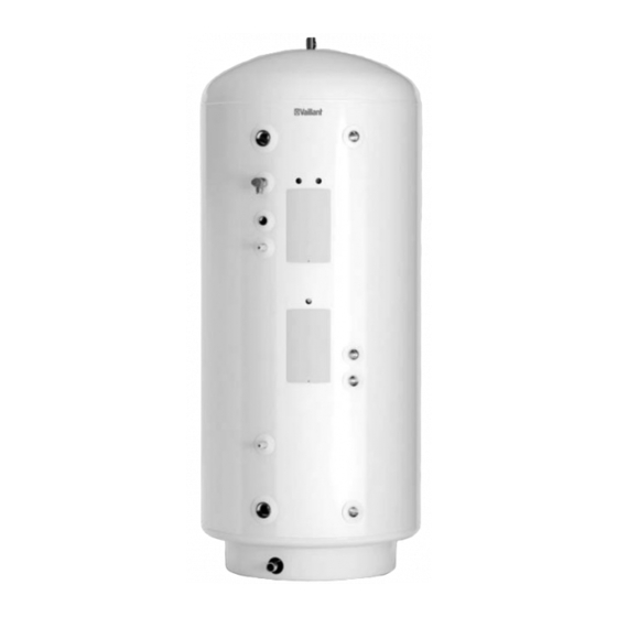
Set-up 4 Unpacking the product Product dimensions Remove the product from its box. Remove the protective film from all of the product's components. Checking the scope of delivery Ø 607 ▶ Check that the scope of delivery is complete. Quant- Description Minimum clearances and installation gend... -
Page 8: Installation
5 Installation Reference Description point 500 mm (on a switching system) ▶ Provide sufficient clearance (B) on at least one side of the product in order to facilitate access for maintenance and repair work. ▶ When using the accessories, observe the minimum clear- ances/installation clearances. - Page 9 Installation 5 5.2.2 Connecting the product to the primary circuit 5.2.4 Installing the safety group Connect the primary circuit to the inlet (12) and the out- Caution. let (18). Excessive pressure in the domestic hot – Minimum diameter of the copper pipe: ≥ 28 mm water cylinder Excessive pressure in the domestic hot water Note...
- Page 10 5 Installation a T-piece for this. The pipe system must continuously Size of Minimum Minimum Maximum Resist- slope downwards, must be visible and must be protec- the outlet diameter diameter permiss- ance per ted against frost. There must be no risk of injury to per- valve of the of the dis-...
- Page 11 Installation 5 5.2.6.1 High-level drain 5.2.8 Installing a secondary return Installing the highest drain is permitted as long as this does not present a danger to anyone in or outside the building at the drain point. Examples of points to consider when decid- ing whether a location is suitable for the highest drain: –...
-
Page 12: Electrical Installation
These thermostat connections make it possible to install a Risk of material damage by drilling connection box from a third-party manufacturer in addition to through the product. the Vaillant thermostat. The product may be damaged by drilling work. 5.3.2.2 Immersion heater ▶... - Page 13 Relay and switch must be rated to maximum sup- heater ply amps. Remove the cover for the electrics on the cylinder. From Vaillant heat pump control (see appropriate schematic for wiring configuration). Install a separate power supply for the immersion heater in accordance with the applicable standards.
- Page 14 5 Installation 5.3.5 Connecting the solar circuit to the power Condition: Installing a third-party control supply GREY BLUE GREEN ORANGE BROWN 60 50 60 50 Solar collector Solar pump Pump output ▶ Connect the thermal cut-out. To do this, consult the in- 60 50 60 50 structions for the control or the multi-functional module.
-
Page 15: Start-Up 6
60 50 60 50 Check whether the drain valve is closed. 230 V signal for a 3-port motorised Vaillant control valve/2-port motorised Open the domestic hot water draw-off valves. valve Open the water supply valve. ▶... -
Page 16: Filling And Purging The Solar Circuit
7 Handing the product over to the end user Inspection and maintenance Remove the cover for the electrics. Set the product's thermostat and the immersion heater's thermostat. Observing inspection and maintenance – Setting the thermostats: 60 ℃ intervals Start up the heat generator. Adhere to the minimum inspection and maintenance inter- Drain the heating circuit as soon as the operating vals. -
Page 17: 11 Customer Service
Customer service 11 11 Customer service To ensure regular servicing, it is strongly recommended that arrangements are made for a Maintenance Agreement. Please contact Vaillant Service Solutions for further details: Telephone: 0330 100 3461 0020235301_03 uniSTOR Installation and maintenance instructions... -
Page 18: Inspection And Maintenance Work
Appendix Appendix Detecting and eliminating faults Fault Possible cause Remedy No flow rate at the valve Water supply valve closed Check and open the valve. Main filter blocked Close the water supply valve, clean the filter and the water pressure reducer. Pressure reducer not installed correctly Check whether the pressure reducer has been installed correctly. - Page 19 Appendix VIH SW GB 500 Pressure of the pressure reducer 0.35 MPa (3.50 bar) Opening pressure in the expansion relief valve 0.6 MPa (6.0 bar) Temperature and pressure expansion relief valve 0.7 MPa (7.0 bar) 90 ℃ Temperature and pressure expansion relief valve Load pressure in the expansion vessel 0.3 MPa (3.0 bar)
- Page 20 Appendix VIH SW GB 500 3-way motorised valve 230/240 V, 50Hz Thermostat 230/240 V, 50Hz IP rating Technical data – Material VIH SW GB 500 Cylinder material Stainless steel (1.4521) Insulation material Glass wool Insulation thickness 65 mm Propellant for insulating material GWP <...
-
Page 21: D Commissioning Checklist
Appendix Commissioning Checklist 0020235301_03 uniSTOR Installation and maintenance instructions... - Page 22 Appendix MAINS PRESSURE HOT WATER STORAGE SYSTEM COMMISSIONING CHECKLIST This Commissioning Checklist is to be completed in full by the competent person who commissioned the storage system as a means of demonstrating compliance with the appropriate Building Regulations and then handed to the customer to keep for future reference. Failure to install and commission this equipment to the manufacturer’s instructions may invalidate the warranty but does not affect statutory rights.
- Page 23 Appendix SERVICE RECORD It is recommended that your hot water system is serviced regularly and that the appropriate Service Record is completed. Service Provider Before completing the appropriate Service Record below, please ensure you have carried out the service as described in the manufacturer’s instructions. SERVICE 01 SERVICE 02 Date:...
-
Page 24: Index
Index Index Article number ............... 5 Basic diagram................ 3 CE marking................5 Checking the pre-charge pressure of the expansion vessel .................. 16 Competent person..............3 Decommissioning ..............16 Decommissioning the product ..........16 Discharge pipe ..............10 Documents ................5 Drain valve ................ - Page 28 0020235301_03 0020235301_03 29.11.2019 Supplier Vaillant Ltd. Nottingham Road Belper Derbyshire DE56 1JT Telephone 0330 100 3461 [email protected] www.vaillant.co.uk © These instructions, or parts thereof, are protected by copyright and may be reproduced or distributed only with the manufacturer's written consent. Subject to technical modifications.