
Related Manuals for Taiden HCS-5100Plus


Summary of Contents for Taiden HCS-5100Plus
- Page 1 New Generation Digital Infrared Language Distribution System Installation and Operating Manual V 2.4...
- Page 2 To protect your hearing avoid high pressure level on earphones. Adjust to a lower and convenient level. If any detailed information needed, please contact your local agent or TAIDEN service center in your region. Any feedback, advice and suggestion about the products is appreciated TAIDEN is the registered trademark of TAIDEN Co., Ltd.
- Page 3 The apparatus should be connected to the MAINS please contact the nearest TAIDEN Service Center. socket-outlet with protective earth. 21. All TAIDEN products are guaranteed for definite time Clean only with dry cloth. (see the WARRANTY CARD for details) excluding the Do not block any ventilation openings.
- Page 4 Important Safety Instructions The lightning flash with an arrowhead symbol, with an equilateral triangle, is intended to alert the user to the presence of uninsulated ‘dangerous voltage’ within the products enclosure that may be of sufficient magnitude to constitute a risk of electric shock to persons.
- Page 5 Lithium battery safety precautions • To change battery please power off and take off the battery immediately. • Keep the battery away from heat sources to prevent fire or explosion. • Do not use a battery that is leaking, deformed, discolored or overheats. •...
-
Page 6: Table Of Contents
Contents Chapter 1. Introduction ....................... 1 1.1 Summary ............................1 1.2 System technology ........................3 1.2.1 Basic system concept ............................. 3 1.2.2 IR radiation ................................3 1.2.3 Signal processing ..............................3 1.2.4 Audio quality modes ............................... 4 1.2.5 Carriers and channels ............................4 1.3 Aspects of infrared distribution ...................... - Page 7 2.6.14 Simultaneous Interpretation ..........................25 2.6.15 Floor Input Sen. Setting ............................. 27 2.6.16 IR Audio In Gain Setting ............................ 27 2.6.17 SI Channel Parameters Setting ........................27 2.6.18 Floor Distribution Setting ........................... 28 2.6.19 Time Setting ................................. 28 2.6.20 Time Display Setting............................28 2.6.21 Interpreter Unit Numbering ..........................
- Page 8 4.7.2 System with two or more transmitters in one room ..................61 4.7.3 System with more than 4 carriers and a radiator under a balcony ..............63 4.7.4 System that mixes TAIDEN radiator with other brand compatible radiator ..........63 Chapter 5. Digital Infrared Receiver ..................64 5.1 Overview .............................
- Page 9 7.1.2 Charging procedure .............................. 76 7.2 Storage case ..........................77 Chapter 8. Fault diagnosis ....................... 78 Chapter 9. Technical data ......................79 9.1 System specification ........................79 9.2 Infrared transmitters ........................80 9.3 Radiators and accessories ......................81 9.4 Receiver ............................82 9.5 Accessory............................
- Page 10 The manual is divided into the following chapters: Chapter 8: Fault diagnosis Chapter 1: Introduction Trouble-shooting guide for simple faults. Introduction to the HCS-5100Plus system, as well as introducing the user into constitution, technical principle and aspects of infrared distribution systems. Chapter 9: Technical data...
- Page 11 Installation & User Guide This manual is applicable to: Digital Infrared Receiver Digital Infrared Transmitter HCS-5100R/04F/08F/16F/32F/40F HCS-5100MA/FS/04F/08F/16F 4, 8, 16, 32, 40 CHs Digital Infrared Receiver (LCD, 4, 8, 16 CHs Digital Infrared Transmitter (compatible with language display, optional rechargeable battery pack or interpreter unit HCS-4100M/HCS-8300M,...
-
Page 12: Chapter 1. Introduction
Chapter 1. Introduction 1.1 Summary HCS-5100Plus series is the new generation system for distribution occasions, such as music distribution digital infrared language distribution. It uses digital (mono as well as stereo). infrared audio transmitting and control technique The HCS-5100Plus series is compliant to IEC 61603-7... - Page 13 The system is composed of one or more of the following: Digital Infrared Receiver Digital Infrared Transmitter HCS-5100R/04F/08F/16F/32F/40F HCS-5100MA/FS/04F/08F/16F 4, 8, 16, 32, 40 CHs Digital Infrared Receiver (LCD, 4, 8, 16 CHs Digital Infrared Transmitter (compatible language display, optional rechargeable battery pack with interpreter unit or HCS-4100M/HCS-8300M, or 2xAA alkaline cells) single-mode optical fiber interface)
-
Page 14: System Technology
1.2.2 IR radiation In the IR receivers, a reverse processing is used to convert the modulated infrared light to separate digital HCS-5100Plus series audio signal is based on audio channels. transmission by modulated infrared radiation (IR). Infrared radiation is part of the electro-magnetic spectrum, which is composed of visible light, radio waves and other types of radiation. -
Page 15: Audio Quality Modes
The table below lists all possible channel combinations per carrier: Figure 1.4 Standard band of HCS-5100Plus infrared language distribution system Figure 1.5 Band allocation Table 1.1 The numbers and quality modes of channels per carrier... -
Page 16: Aspects Of Infrared Distribution
The sensitivity of a receiver is at its best when it is 1.3.1 Ambient lighting aimed directly towards a radiator. To minimize the HCS-5100Plus can be operated without any problem disadvantage of this aspect, HCS-5100R/RA/F receiver even if fluorescent lamps (with or without electronic... -
Page 17: Positioning The Radiators
dark grey area in figure 1.8 to figure 1.10). In this area, 1.3.5 Positioning the radiators the direct signal is strong enough to ensure proper Because infrared radiation can reach a receiver directly reception when the receiver is directed towards the and/or via diffused reflections, it’s important to take this radiator. -
Page 18: Overlapped Footprints And Multipath Effects
1.3.6 Overlapped footprints multipath If the path of the infrared signals is blocked, e.g. under effects balconies, at least one additional radiator is needed to If footprints of two radiators overlap, the total coverage cover the ‘shaded’ area (see figure 1.12). area maybe larger than the sum of the two separate footprints. -
Page 19: Chapter 2. Digital Infrared Transmitter
Chapter 2. Digital Infrared Transmitter 2.1 Overview The HCS-5100M/F transmitter is the heart of the HCS-5100Plus system. Up to 40 unbalanced audio signals can be accepted (under combination mode) via digital/analog audio signal input connectors. It can be connected to HCS-8300 or HCS-4100/50 congress... -
Page 20: Functions And Indications
2.2 Functions and indications Front of HCS-5100M/F Rear of HCS-HCS-5100MA/F Rear of HCS-5100MA/FS/F Rear of HCS-5100MC/FD Rear of HCS-5100MC/F Figure 2.1 HCS-5100M/F Digital Infrared Transmitter... - Page 21 Figure 2.1: 1. Standby button with indicator 17. INTERPRETER’S UNIT / MAIN UNIT When the switch is off, it does not completely For connecting to interpreter unit For disconnect the unit from mains connecting HCS-4100M/50 2. “MENU” button HCS-8300M congress main unit via CBL6PP-02 After starting initialization:, press the “MENU”...
-
Page 22: Installation
2.3 Installation The transmitter can be fixed in a standard 19-inch cabinet. The transmitter is equipped with a pair of fixing brackets ①. First unscrew the lateral screws ② from the housing. Then fasten the brackets with these screws and put the CMU in the cabinet. Finally fix the four holes ③... -
Page 23: Connection
2.4 Connection 2.4.2 To external audio sources Typical system connection includes: to another transmitter HCS-5100M/F transmitter has up to 40 audio inputs to external audio sources (depends on transmitter type) for connecting to to emergency signal switch external unbalanced audio sources (such as other ... -
Page 24: To Interpreter Unit
Paperless Multi-media Congress System HCS-5100MC/F transmitter do not have optical fiber interface, 6P-DIN interface or DCS interface, it can be connected to TAIDEN HCS-8300M congress main unit through TAIDEN HCS-8300MO 8 Channels Audio Output Device. The output of HCS-8300MO should be... - Page 25 Figure 2.8 HCS-5100MA/F transmitter connecting to HCS-8300M congress main unit Figure 2.9 HCS-5100MC/F transmitter connecting to HCS-8300M congress main unit through HCS-8300MO...
-
Page 26: Menu Structure
2.5 Menu structure 2.5.1 Transmitter menu structure (work mode: Master-Analog) Figure 2.12a Transmitter menu structure (work mode: Master-Analog) -
Page 27: Transmitter Menu Structure (Work Mode: Master- Interp. U)
2.5.2 Transmitter menu structure (work mode: Master- Interp. U) Figure 2.12b Transmitter menu structure (work mode: Master- Interp. U) -
Page 28: Transmitter Menu Structure (Work Mode: Master- Central U)
2.5.3 Transmitter menu structure (work mode: Master- Central U) Figure 2.12c Transmitter menu structure (work mode: Master- Central U) -
Page 29: Transmitter Menu Structure (Work Mode: Master-Dante)
2.5.4 Transmitter menu structure (work mode: Master-Dante) Figure 2.12d Transmitter menu structure (work mode: Master-Dante) -
Page 30: Transmitter Menu Structure (Work Mode: Bypass)
2.5.5 Transmitter menu structure (work mode: Bypass) Figure 2.12e Transmitter menu structure (work mode: Bypass) -
Page 31: Configuration And Operation
2.6 Configuration and operation Via an interactive menu on the LCD and 4 operation buttons. A) Starting initialization: “Master - Dante” mode Switch on the HCS-5100M/F transmitter. The current When the HCS-5100MC/FD transmitter is connected to status of the transmitter will be displayed on the LCD: the Dante network via the Dante interface, the simultaneous interpretation status will be displayed on the LCD. -
Page 32: Work Mode
→“Parameters Backup/Restore” →“About Dante” →“Machine Rename” →“About” In “Bypass” mode: →“Work Mode” →“Operation Language Setting” In “Master - Interp. U” mode: →“Work Mode” →“Network Setting” →“Simultaneous Interpretation” →“Machine Rename” →“Floor Input Sen. Setting” →“About” →“IR Audio In Gain Setting” →“SI Channel Parameters Setting” →“Floor Distribution Setting”... -
Page 33: Carrier(S) Setting
c). Transmitter needs to restart to implement working b) Use the “MENU” button to the save channel number mode configuration. Use the “/” button to select setting. reset now or not. 4) Audio quality a) Go to the audio quality setting interface; 2.6.2 Carrier(s) Setting b) Press the “MENU”... -
Page 34: Audio Input Sensitivity
2.6.4 Audio Input Sensitivity “Stereo Music”: If “Play music”, stereo music from 2 channels “Input sensitivity” includes 2 submenus: auxiliary audio input will be distributed to all output • “All”: adjust all channels input sensitivity channels, usually playing music when •... -
Page 35: Alarm Setting
2.6.7 Alarm Setting 2) Setting up “Subnet Mask” and “Gateway”: Same chronological order as for the “IP address” set Enable alarm function or not. Note: “IP address”, “Subnet Mask” and “Gateway” of the system software should correspond a). Use the “/” button to select “Yes” or “No”; with the above transmitter settings, else b). -
Page 36: Machine Rename
2.6.12 Machine Rename Operation steps: Set alias for the HCS-5100M with a maximum length of a). Setup the number of interpretation channels 16 characters or less. a). Press the “MENU” button to enter the name setting Use the “/” button to switch the number of interface;... - Page 37 d). Set interlock mode between booths f). Set switch outgoing channel When mic. on Select interlock mode between booths, includes: Set switch outgoing channel when microphone on for "INTERLOCK" HCS-8385. "OVERRIDE" "OVERRIDE-BC" 1). Use the “/” button to switch between “Enable” and “Disable”, 1).
-
Page 38: Floor Input Sen. Setting
Note: If channel B and C of a booth have no output, this booth can not be set as auto-relay booth. “None” stands for no language output from channel B; 2.6.15 Floor Input Sen. Setting “All” stands for the language of channel B which can be any of the selected languages. -
Page 39: Floor Distribution Setting
Under channel state interface, press “MENU” to select 2.6.21 Interpreter Unit Numbering the channel number or parameter and press “/” to All HCS-4385U/50 interpreter units must be numbered change the channel number or parameter. when the system is used for first time or when adding Note: or replacing interpreter units. -
Page 40: Channel Gain Setting
2.7 Monitor For testing the transmitter, the front panel has a 2.6.24 Channel Gain Setting monitoring facility including a monitor channel selector, “Input sensitivity” includes 2 submenus: a monitor earphone jack and a monitor volume control • “All”: adjust all channels input gain knob (please refer to figure 2.1). -
Page 41: Chapter 3. Digital Infrared Transmitter
Chapter 3. Digital Infrared Transmitter 3.1 Overview The HCS-5100M/A transmitter is the heart of the HCS-5100Plus system. Up to 40 unbalanced audio signals can be accepted (under combination mode) via digital/analog audio signal input connectors. It can be connected to HCS-8300 or HCS-4100/50 congress... -
Page 42: Functions And Indications
3.2 Functions and indications Front of HCS-5100M/A Rear of HCS-HCS-5100MA/A Rear of HCS-5100MA/FS/A Rear of HCS-5100MC/AD Rear of HCS-5100MC/A Figure 3.1 HCS-5100M/F Digital Infrared Transmitter Figure 3.1: 1. Standby button with indicator 3. Operation knob For LCD menu operation; 2. - Page 43 5. Mini IR radiator 18. Power on/off 4 IREDs transmitting the same infrared signal as 19. Power supply the radiator output for monitor purpose 20. Single-mode fiber, SC connecter For connecting to the congress main unit, 6. A type USB interface ...
-
Page 44: Installation
3.3 Installation HCS-5100M/A series Digital Infrared Transmitter can be fixed in a standard 19-inch cabinet. Put the main unit in the cabinet and fix the four holes up with screws ①. Figure 3.2 Installation of transmitter In addition, 1U metal stripes are included as decoration to be installed between the transmitters in the cabinet. -
Page 45: Connection
3.4 Connection 3.4.2 To external audio sources Typical system connection includes: to another transmitter HCS-5100M/A transmitter has up to 40 audio inputs to external audio sources (depends on transmitter type) for connecting to to emergency signal switch external unbalanced audio sources (such as other ... -
Page 46: To Interpreter Unit
Paperless Multi-media Congress System HCS-5100MC/A transmitter do not have optical fiber interface, 6P-DIN interface or DCS interface, it can be connected to TAIDEN HCS-8300M congress main unit through TAIDEN HCS-8300MO 8 Channels Audio Output Device. The output of HCS-8300MO should be... - Page 47 Figure 3.8 HCS-5100MA/A transmitter connecting to HCS-8300M congress main unit Figure 3.9 HCS-5100MC/A transmitter connecting to HCS-8300M congress main unit through HCS-8300MO...
-
Page 48: Menu Structure
3.5 Menu structure 3.5.1 Transmitter menu structure (work mode: Master-Analog) Figure 3.10a Transmitter menu structure (work mode: Master-Analog) -
Page 49: Transmitter Menu Structure (Work Mode: Master- Interp. U)
3.5.2 Transmitter menu structure (work mode: Master- Interp. U) Figure 3.10b Transmitter menu structure (work mode: Master- Interp. U) -
Page 50: Transmitter Menu Structure (Work Mode: Master- Central U)
3.5.3 Transmitter menu structure (work mode: Master- Central U) Figure 3.10c Transmitter menu structure (work mode: Master- Central U) -
Page 51: Transmitter Menu Structure (Work Mode: Master-Dante)
3.5.4 Transmitter menu structure (work mode: Master-Dante) Figure 3.10d Transmitter menu structure (work mode: Master-Dante) -
Page 52: Transmitter Menu Structure (Work Mode: Bypass)
3.5.5 Transmitter menu structure (work mode: Bypass) Figure 3.10e Transmitter menu structure (work mode: Bypass) -
Page 53: Configuration And Operation
3.6 Configuration and operation Via an interactive menu on the LCD and the operation In “Master - Interp. U” mode: →“Work Mode Setting” knob. →“SI Status” →“Simultaneous Interp.” A) Starting initialization: →“Floor Input Sen.” →“Monitor Setting” Switch press standby key, →“SI Ch. -
Page 54: Work Mode Setting
→“Network Setting” 3.6.1 Work Mode Setting →“Operation Language” a) Rotate the operation knob to switch between →“Use Testing Audio” “Master” and “Bypass”; →“Backup/Restore” →“Machine Rename” →“Screensaver” →“About” →“About Dante” →“Return” “Master”, Press the operation knob to confirm and go to step b); In “Bypass”... -
Page 55: Carrier(S) Setting
3.6.2 Carrier(s) Setting b) Rotate the operation knob to switch channel number (in the case of more than one channel). Users can set the status of every carrier, the number of “Audio input:” indicates the current channel channels and the audio quality. corresponding to the HCS-5100M transmitter audio input channel;... -
Page 56: Auxiliary Input Setting
• “All”: auxiliary audio input will be distributed to all output Rotate the operation knob to adjust the max. level for channels, usually playing music when all audio inputs and then press the operation knob to adjournment. save. Range from –12 dBV - +12 dBV. “Mono + Emergency”: Once the alarm signal is turned on, the emergency signal from Aux-R audio input will be distributed to all... -
Page 57: Monitor Setting
3.6.7 Monitor Setting 3.6.9 Operation Language The front panel has a monitor earphone jack for Select the LCD display language from simplified testing the transmitter. Chinese, Traditional Chinese, English, etc. Other languages can be added by the user through LCD_Designer software operation. •... -
Page 58: Use Testing Audio
2) Setting up “Subnet Mask” and “Gateway”: 3.6.13 Machine Rename Same chronological order as for the “IP address” set Set alias for the HCS-5100M with a maximum length of 16 characters or less. Note: “IP address”, “Subnet Mask” and “Gateway” of the system software should correspond with the above transmitter settings, else connection error will occur. -
Page 59: Status
3.6.16 SI Status b). Setup language for channel When the HCS-5100MA/A transmitter is connected to the simultaneous interpretation unit via the 6P-DIN interface, the simultaneous interpretation status will be displayed on the LCD (F: floor channel, +: SI channel used, ×: no use). It once displays 8 channel status, 1). - Page 60 “OVERRIDE-BC” mode enables A/B/C g). Select language of output channel for the booth channel of an interpreter unit in another booth To distribute the interpretation languages separately, to override an occupied B/C channel in A/B/C channels are provided in each interpretation unit. another booth, but supplying the same The language setting of A/B/C channels for all channel;...
-
Page 61: Floor Input Sen
3). Repeat 1) - 2) to setup output channel A/B/C 3.6.18 Floor Input Sen. language for all booths; 4). Press the operation knob to confirm selected interlock mode and go to step h). h). Auto-Relay booth Setting Setup Auto-Relay booth. a). -
Page 62: Time Setting
b). Press the operation knob to save and return to the c). Press the operation knob to stop number and return upper level menu. to the upper level menu. 3.6.21 Time Setting 3.6.24 Fiber Port Setting Setup system clock. Enable/disable the fiber port. a). -
Page 63: About Dante
audio inputs. Range from –12 dB - +12 dB. • “Per Input”: a) Press the operation knob to switch channel number; b) Rotate the operation knob to adjust the gain for each audio input. Range from –12 dBV - +12 dBV. 3.6.27 About Dante Dante software information will be displayed, including: Dante version, device version and device name. -
Page 64: Chapter 4. Digital Infrared Radiator
Chapter 4. Digital Infrared Radiator 4.1 Overview This unit accepts carrier signals generated by the transmitter and emits infrared radiation, carrying up to 40 audio distribution channels. Radiators are connected to the HF (BNC) connectors of the IR transmitter. A maximum of 30 radiators, daisy chained connected, can be connected to each of these outputs. -
Page 65: Functions And Indications
4.2 Functions and indications Figure 4.1 Radiator (front) Figure 4.1: 1. Power indicator 2. Temperature protection indicator Figure 4.3 Radiator (side face) 3. Input signal indicator 4. Fault indicator Figure 4.3: 5. Infrared emission area 1. Delay compensation indicator 2. Delay compensation switch (-/+) 3. -
Page 66: Position Planning
4.3 Position planning For position planning, please read section Guaranteed rectangular footprints also understand and consider every aspect of infrared calculated with the footprint calculation tool (available distribution. on the documentation CD-ROM). The given values are for one radiator only, they do not take into consideration the beneficial effects of overlapping 4.3.1 Rectangular footprints footprints and reflections (see section 1.3.6). -
Page 67: Cabling
4.3.3 Cabling Signal delay differences can occur because of the differences in the cable length from the transmitter to each radiator. In order to avoid the risk of black spots (see section 1.3.6), use equal cable length from transmitter to radiator if possible (see figure 4.7). Figure 4.7 Radiators with equal cable length If radiators are loop-through, the cabling between each radiator and the transmitter should be as symmetrical... -
Page 68: Mounting
4.4 Mounting The radiator can be permanently installed onto the wall, 4.4.2 Wall mounting under a ceiling or a balcony by bracket. The mounting angle can be adjusted for optimal coverage through A separate bracket (HCS-5100TBZJ) is optional for angle adjust handle. wall mounting (refer to figure 4.10). -
Page 69: Ceiling Mounting
4.4.3 Ceiling mounting The radiator can be fixed to the ceiling by using the Infrared radiator installing on a soft wall (such as built-in bracket. Please make sure to have enough plaster): space for a proper air flow around the radiator when 1. -
Page 70: Connecting To Transmitter
4.5 Connecting to transmitter 4.6 Output power selection There are six functionally identical HF signal output The radiator can be switched to half power output. This interfaces on the transmitter. Each one can connect up is usually done when full power output is not needed, to 30 radiators by daisy chain. -
Page 71: Setting The Radiator Delay Switches
4.7 Setting the radiator delay switches As described in section 1.3.6, signals picked up by the Take signal delay rate as 5.0 ns/m (value as an receiver from two or more radiators can cause black example for calculation only, real value depends on spots due to delay differences. -
Page 72: System With Two Or More Transmitters In One Room
Table 4.1 Calculation of the cable signal delays Radiator Total cable Cable length Cable signal delay Signal delay Delay switch number length L(m) difference L -L(m) per meter (ns/m) difference (ns) position 30+20=50* 50 - 50 = 0 0*5.0 = 0 0/25 = 0 50 - 30 = 20 20*5.0 =100... - Page 73 Figure 4.17 System with master and bypass transmitter in multi purpose room Table 4.2 Calculation of the master-bypass signal delay Master-bypass transmitter cable length Cable signal delay per meter Master-bypass signal delay (ns/m) (ns) 50*5.0=250 Table 4.3 Calculation of the delay switch positions of a system with two transmitters Cable Cable Master-bypass...
-
Page 74: System With More Than 4 Carriers And A Radiator Under A Balcony
Other brands on the market have a higher electric input to light output delay - for example 760 ns which means a 400 ns higher delay compared to TAIDEN HCS-5100 (equivalent to the delay caused by about 80 m of cable, i.e.16 steps of delay switch position). -
Page 75: Chapter 5. Digital Infrared Receiver
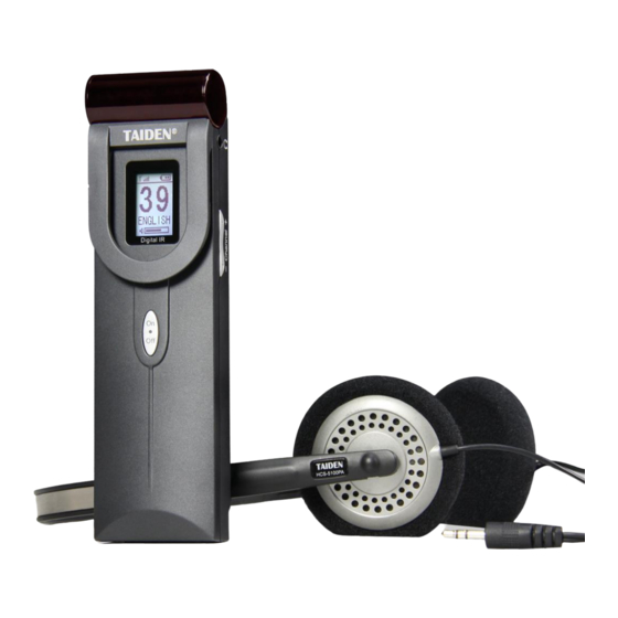
Chapter 5. Digital Infrared Receiver 5.1 Overview HCS-5100R/RA is a series of Digital Infrared Receivers, which can receive up to 40 language channels. Both rechargeable Li-ion battery and disposable battery can be used. The receiver is equipped with channel selector, volume control, power switch, Ø... -
Page 76: Functions And Indications
5.2 Functions and indications Note: When the receiver is not used, please disconnect the earphone. This ensures that the receiver is totally switched-off and no energy is consumed from the batteries or the battery pack. Figure 5.1 HCS-5100R/RA receiver Figure 5.1: 1. -
Page 77: Operation
5.3 Operation The receiver only works when an earphone is connected and the receiver switches to stand-by state. Push shortly Note: When the receiver will not be used in a long on the power switch button to switch on the receiver. The channel number is shown on the LCD. -
Page 78: Testing The Coverage Area
5.4 Testing the coverage area To make sure that the whole area is covered with direction of the receiver b) shaded-off or simply adequate IR radiation and avoiding thus black spots, an switched-off. IR radiation, reflected from a surface with extended reception quality test should be done. -
Page 79: Earphones
5.5 Earphones The earphones are connected to the conference units EP-960BH headphone via a Ø 3.5 mm stereo jack. Suitable earphone types include: EP-820AS single earphone Any other compatible type (see chapter 9, Technical Data). EP-829 single earphone 5.6 Li-ion Rechargeable Battery Pack ... -
Page 80: Chapter 6. Web Server
Chapter 6. Web server Running environment: browser for Firefox29.0, Google25.0, IE10 or higher. 6.1 Login and exit The user inputs the IP address of CMU into the Web browser to login. The default UserName is “admin” and default Password is “123456”, the password can be changed after login. The default username is administrators that cannot be deleted. -
Page 81: Conference Management
There are two buttons in the right top of the interface: Password Change: click this button and the below dialog box is shown: Input the Old Password, New Password and Password Confirm, and then click the “OK” button to change the password. Note: Password only supports a sequence of numbers or letters (case sensitive) with maximal 20 characters. -
Page 82: Normal
6.2.1 Normal User can assign the quantity and language of the SI channels, or play music. The interface is shown in the following figure: Figure 6.3 Normal setting Channels: set up the number of simultaneous interpretation channel; CH: assign a language from the list for each channel. Languages also can be added or deleted conveniently, ... -
Page 83: Carrier Setting
Send to CMU: save the current setting and send it to the main unit; Music: plays music to all channels. 6.2.2 Carrier Setting Carrier setting includes AUX. mode setting, carrier setting, etc.. Figure 6.4 Carrier setting AUX. Mode: includes “Stereo Music” and “Mono+Emergency”; “Stereo Music”: stereo music from 2 channels auxiliary audio input will be distributed to all output channels, usually for playing music when adjournment;... -
Page 84: Sensitivity
6.2.3 Sensitivity Adjust the sensitivity of each channel and auxiliary audio. The interface as shown in the following figure: Figure 6.5 Sensitivity Setting All Channels: adjust the max. level for all audio inputs. Range from –12 dBV - +12 dBV; ... -
Page 85: Setup
6.2.4 S.I. Setup Setup of simultaneous interpretation channel and the outgoing languages for the A, B, C channels for each interpreter booth in “Master-Interp.U” mode. The interface as shown in the following figure: Figure 6.6 S.I. Setup Channels: set up the number of simultaneous interpretation channel; ... - Page 86 Note: The user-defined language must include the full name and its abbreviation. The full name only supports a sequence of numbers or letters (case sensitive) with maximal 8 characters and the abbreviation supports 3 characters at most.
-
Page 87: Chapter 7. Charging Case And Storage Case
Chapter 7. Charging Case and Storage case 7.1 Charging case 7.1.1 Overview 7.1.2 Charging procedure The charging Case can charge up to 60 receivers at a Connect power cord; time. It uses universal power supply with automatic Switch on; voltage matching. There is a charging indicator on the Insert receiver;... -
Page 88: Storage Case
7.2 Storage case HCS-5100KS storage case is used to store and to transport IR receivers (HCS-5100R/RA/F). It can contain 100 receivers in 1 storage case. Figure 7.2 HCS-5100KS storage case... -
Page 89: Chapter 8. Fault Diagnosis
Chapter 8. Fault diagnosis Some simple trouble-shooting instructions are provided in this chapter. If more serious faults arise, please contact a qualified technician. Fault Solution Confirm that transmitter power cord is connected correctly and the power is Transmitter display does not light up switched on. -
Page 90: Chapter 9. Technical Data
Chapter 9. Technical data 9.1 System specification System performance Cabling and system limits Conforms to IEC 60914, the international standard for Cable type 75 Ohm RG59 conference systems Maximum number of radiators 30 per HF output Conforms to IEC 61603-7, the international standard Maximum cable length 300 m per HF output for digital infra-red transmission of audio signals for... -
Page 91: Infrared Transmitters
9.2 Infrared transmitters 5100MA/FS/F 5100MA/F 5100MC/FD 5100MC/F Type 5100MA/FS/A 5100MA/A 5100MC/AD 5100MC/A Mains voltage AC 100 V – 240 V, 50 Hz / 60 Hz Power consumption Maximal 25 W -6 dBV - +18 dBV Balanced audio input: Audio input Unbalanced audio inputs : -12 dBV - +12 dBV Output: BNC×6... -
Page 92: Radiators And Accessories
9.3 Radiators and accessories Type HCS-5100T/15B HCS-5100T/25B HCS-5100T/35B Mains voltage AC 100 V – 240 V, 50 Hz / 60 Hz 35 W 62 W 120W Power consumption Power consumption (standby) 75 Ω HF input/output ±22° Angle of half intensity (mm)... -
Page 93: Receiver
9.4 Receiver Type HCS-5100R/RA/F Supply voltage 2.5 V – 4.2 V, 3.0 V nominal ) 38 mA( 32 Ohm headphone Power consumption ) 0 mA( unplug headphone jack IR irradiance level 4mW/m per carrier 270° Angle of sensitivity 450 mVrms Headphone output level at 3.0 V (speech at maximum volume, 32 Ohm headphone) -
Page 94: Accessory
9.5 Accessory 9.5.1 Earphones EP-960BH headphone EP-820AS Single Earphone • Used with the receiver/conference unit • Used with the receiver/conference unit • Hi-Fi sound quality • Hi-Fi sound quality • 150 Ohm×2, Ø 3.5 mm stereo jack • Ø... -
Page 95: Storage Case (Hcs-5100Ks)
9.6 Connection details 9.5.4 Storage Case (HCS-5100KS) 9.6.1 Mains cables Physical characteristics Blue Neutral Brown Live Dimensions (H×W×D) 669×307×205 mm Green/Yellow Earth/Ground Weight 6 kg (excl. receivers) 14kg (incl. 100 receivers, excl. batteries) 9.6.2 Audio cables Color Blue 3-pole XLR connector (female) Pin 1 Earth Pin 2... -
Page 96: Guaranteed Rectangular Footprints
9.7 Guaranteed rectangular footprints HCS-5100T/15B HCS-5100T/25B HCS-5100T/35B Mounting N0. of Mounting Area Length Width Offset Area Length Width Offset Area Length Width Offset height carriers angle L(m) W(m) X(m) L(m) W(m) X(m) L(m) W(m) X(m) H(m) 1674 1632 1066 -3.5 -7.5 1581 1260... -
Page 97: Display Language List
9.8 Display language list Chinese English Chinese English 639-3 639-2/5 639-1 639-3 639-2/5 639-1 原声 爱尔兰语 Floor Irish 阿尔巴尼亚 哈萨克语 Albanian Kazakh 阿拉伯语 吉尔吉斯语 Arabic Kirghiz 保加利亚语 老挝语 Bulgarian 加泰罗利亚 蒙古语 Catalan Mongolian 汉语 尼泊尔语 Chinese Nepali 捷克语 塔吉克语 Czech Tajik 丹麦语... - Page 98 Chinese English 639-3 639-2/5 639-1 Chinese English 639-3 639-2/5 639-1 奥里亚语 茨瓦纳语 Oriya Tswana 旁遮普语 乌尔都语 Panjabi Urdu 罗曼什语 威尔士语 Romansh Welsh 梵文 祖鲁语 Sanskrit Zulu 信德语 壮族语 Sindhi Zhuang Sinhala / 僧加罗语 傣族语 Sinhalese Southern 梭托语 维吾尔语 Uighur Sotho / Sotho 斯瓦西里语...
- Page 99 TAIDEN INDUSTRIAL CO., LTD. 6/F, Block B, Future Plaza, 6060 Qiaoxiang Rd, Nanshan District, Shenzhen,China P.C.: 518053 Copyright by TAIDEN Website: http://www.taiden.com Last Revision: 04/2020...