YOKOGAWA SL1000 User Manual
High-speed data acquisition unit
Hide thumbs
Also See for SL1000:
- User manual (239 pages) ,
- User manual (96 pages) ,
- User manual (51 pages)
Table of Contents
Quick Links
Table of Contents

Related Manuals for YOKOGAWA SL1000


Summary of Contents for YOKOGAWA SL1000
- Page 1 SL1000 High-Speed Data Acquisition Unit IM 720120-01E 1st Edition...
- Page 2 Product Registration Thank you for purchasing YOKOGAWA products. YOKOGAWA provides registered users with a variety of information and services. Please allow us to serve you best by completing the product registration form accessible from our homepage. http://www.yokogawa.com/tm/ PIM 103-02E...
- Page 3 Thank you for purchasing the SL1000 High-Speed Data Acquisition Unit. This user’s manual contains useful information about the instrument’s functions and operating procedures and lists the handling precautions of the SL1000. To ensure correct use, please read this manual thoroughly before beginning operation.
-
Page 4: Checking The Contents Of The Package
300 VA MAX 50/60 Hz MODEL Suffix Code Description 720120 SL1000 High-Speed Data Acquisition Unit 8 slots, up to 128 MW memory With 1 license for the Xviewer Standard Edition (701992-SP01) Power cord UL/CSA Standard power cord (Part No.: A1006WD) Maximum rated voltage: 125 V, Maximum rated current: 7 A VDE Standard Power Cord (Part No.: A1009WD) - Page 5 Maximum rated voltage: 250 V, Maximum rated current: 10 A A1064WD GB Standard Power Cord Maximum rated voltage: 250 V, Maximum rated current: 10 A Acquisition Software (CD) B8073ZA Acquisition software used to configure and control the SL1000. Soft case B8081HG For storing accessories. Cover panels B8073CY For empty module slots.
- Page 6 Checking the Contents of the Package Modules (Sold Separately) Check that the MODEL indicated on the module is what you ordered. MODEL Name Minimum Abbreviation Q’ty 720210 High-Speed 100 MS/s, 12-Bit Isolation Module (2CH) HS100M12 701250 High-Speed 10 MS/s, 12-Bit Isolation Module HS10M12 701251 High-Speed High-Resolution 1 MS/s, 16-Bit Isolation HS1M16...
- Page 7 Checking the Contents of the Package Optional Accessories (Sold Separately) The optional accessories below are available for purchase separately. For information and ordering, contact your nearest YOKOGAWA dealer. Model Part Min. Specifications Number ’ Isolated Probe 700929 1 1000Vrms-CAT II, for the 701250/701251/701260/720210 (10:1)
- Page 8 Checking the Contents of the Package Current Probe Current Probe Isolated Probe Current Probe 701931 701930 700929 701933 Safety Mini-Clip Passive Probe (10:1) 1:1 BNC Safety Alligator Clip (hook type) 701940 Adapter Lead (dolphin type) 701959 701901* 701954 Alligator Clip Adapter Alligator Clip Adapter Fork Terminal 1:1 BNC-Alligator...
-
Page 9: Safety Precautions
The general safety precautions described herein must be observed during all phases of operation. If the instrument is used in a manner not specified in this manual, the protection provided by the instrument may be impaired. Yokogawa Electric Corporation assumes no liability for the customer’s failure to comply with these requirements. - Page 10 To prevent electric shock or fire, be sure to use the power cord supplied by YOKOGAWA. The main power plug must be plugged into an outlet with a protective earth terminal. Do not disable this protection by using an extension cord without protective earth grounding.
- Page 11 Safety Precautions Precautions to Be Taken When Using the Probes • If you are measuring high voltages using the 720210 (HS100M12), 701250 (HS10M12) or the 701251 (HS1M16), use the isolated probe (700929) or 1:1 safety cable (combination of 701901 and 701954). •...
-
Page 12: Waste Electrical And Electronic Equipment
With reference to the equipment types in the WEEE directive Annex 1, this product is classified as a “Monitoring and Control instrumentation” product. Do not dispose in domestic household waste. When disposing products in the EU, contact your local Yokogawa Europe B. V. office. IM 720120-01E... -
Page 13: How To Use This Manual
How to Use This Manual Structure of the Manual This user’s manual consists of the following sections. Chapter Title Description Names and Uses of Parts Describes the names and uses of each part and the screen display. Explanation of Functions Describes the measurement principles and the functions of the instrument. - Page 14 How to Use This Manual Conventions Used in This Manual Unit k: Denotes 1000. Example: 100 kS/s (sampling rate) K: Denotes 1024k. Example: 710 KB (file size) Bold Characters Bold characters used in the procedural explanations indicate characters that are marked on the panel keys or the characters of the soft keys displayed on the screen menu.
-
Page 15: Table Of Contents
Contents Checking the Contents of the Package ..................ii Safety Precautions........................vii Waste Electrical and Electronic Equipment .................x How to Use This Manual........................xi Chapter 1 Names and Uses of Parts Front Panel and Rear Panel ................... 1-1 Keys and Indicators ....................... 1-3 Display .......................... - Page 16 Contents Chapter 7 Specifications Input Section ........................7-1 Display Section ....................... 7-1 Storage ..........................7-1 External I/O Section ....................... 7-2 Computer Interface ......................7-3 7.6 General Specifications ....................7-4 External Dimensions ...................... 7-7 Appendix Appendix 1 TCP and UDP Port Numbers Used in Ethernet Communications ....App-1 Index IM 720120-01E...
-
Page 17: Chapter 1 Names And Uses Of Parts
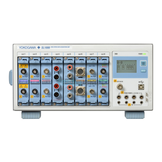
Names and Uses of Parts Front Panel and Rear Panel Front Panel Handle Input module installation slots Used to carry the SL1000. A total of 8 slots. For a description of the indicated → Section 3.1 For the procedure to install or remove information, see section 1.3. - Page 18 GO/NO-GO output terminals Delivers GO/NO-GO determination output signals. → Section 5.6 Note Be sure to use the DIP switch at the factory default setting. If you change the setting, the SL1000 may not operate properly. Factory default settings Status OFF IM 720120-01E...
-
Page 19: Keys And Indicators
Keys and Indicators POWER TRIG’D START/ STOP DISPLAY Name Function START/STOP key Starts or stops the measurement or measurement and recording. The key illuminates while measurement is in progress. ON: Measuring OFF: Stopped DISPLAY key Switches the screen. Module status screen, system error screen, and communication parameter screen POWER indicator Displays the power status. - Page 20 Display Screens The available SL1000 screens are the module status screen, error screen, and communication parameter screen. Startup or timeout DISPLAY DISPLAY DISPLAY Communication Module status Error screen parameter screen screen • At startup, the module status screen appears. • Press DISPLAY to switch screens.
- Page 21 For details on errors and messages, see section 6.2. Instrument No. Displays the SL1000 unit's instrument number. IP address Displays the IP address setting of the SL1000. Status icon Indicates the SL1000 status using icons. • System error icon Blinking: System error status* OFF: Normal system status •...
-
Page 22: Chapter 2 Explanation Of Functions
Chapter 2 Explanation of Functions System Configuration and Block Diagram System Configuration • External clock input Internal hard disk (option) • External trigger input • GO/NO-GO output • Trigger output • Alarm output • USB interface • Ethernet interface (option) Measured item Signal input •... - Page 23 2.1 System Configuration and Block Diagram Block Diagram Module Block Diagram CPU Block Diagram Acquisition Block Diagram Plug-in Module CH1 - CH16 720210(HS100M12) ACQ Memory ASIC 100MW Main Memory Isolator 128 MB Isolation Block 701250(HS10M12) ASIC ATA-4 40 GB (Option) Isolator Isolation Block USB Port...
- Page 24 2.1 System Configuration and Block Diagram Signal Flow on the SL1000 The flow of the signal applied to the input terminal varies depending on the input module. Here, the High-Speed 100 MS/s, 12-Bit Isolation Module (720210 (HS100M12)) will used an example to describe the signal flow. (For details on the signal flow on each module, see the block diagram.)
-
Page 25: Input Modules
Input Modules The SL1000 supports the following 12 input modules. MODEL Name Abbreviation 720210 High-Speed 100 MS/s, 12-Bit Isolation Module HS100M12 701250 High-Speed 10 MS/s, 12-Bit Isolation Module HS10M12 701251 High-Speed 1 MS/s, 16-Bit Isolation Module HS1M16 701255 High-Speed 10 MS/s, 12-Bit Non-Isolation Module... -
Page 26: Operating Configuration
Operating Configuration Online Operation In this configuration, you connect the SL1000 to a PC via the USB or Ethernet (option) interface and use a dedicated software program to specify measurement conditions and carry out measurements. You use a dedicated software program to start or stop measurements. The SL1000 measures and holds the data in its acquisition memory, and the PC reads it. - Page 27 You cannot specify measurement conditions directly on the SL1000. To make measurements in the standalone configuration, specify the SL1000 measurement conditions online in advance. In standalone configuration, you can connect the SL1000 to a PC via the USB or Ethernet (option) interface after measurements are complete and read the measured data on a PC.
-
Page 28: Chapter 3 Making Preparations For Measurements
If you notice any symptoms of trouble such as unusual odors or smoke coming from the instrument, immediately turn OFF the power switch and unplug the power cord. If these symptoms occur, contact your nearest YOKOGAWA dealer. Handle the Power Cord with Care Do not place objects on top of the power cord and keep it away from any heat sources. - Page 29 3.1 Handling Precautions Carry the Instrument Properly First, remove the power cord and connection cables. The instrument weighs approximately 6 kg without any modules installed and 9 kg when eight modules are installed. Carry the instrument by the handles as shown below or carry it with both hands. HI GH -S PE IS IT...
-
Page 30: Installing The Instrument
Installing the Instrument Installation Orientation WARNING To prevent fire, never use the instrument with the rear panel facing down. There are vent holes for the cooling fan on the rear panel. Placing the instrument with the rear panel down can cause a fire when the instrument malfunctions. •... - Page 31 3.2 Installing the Instrument Installation Conditions Install the instrument in a place that meets the following conditions: Well-Ventilated Location There are vent holds on the right and bottom panels of this instrument. In addition, there are exhaust holes for the cooling fan on the rear panel. To prevent internal overheating, allow for enough space around the instrument (see the figure below) and do not block the vent and inlet holes.
- Page 32 3.2 Installing the Instrument Storage Location • We strongly recommend you store the SL1000 in an environment with a temperature between 5 and 40°C and a relative humidity between 20 to 80%RH. • When storing the SL1000, avoid the following locations.
-
Page 33: Installing Modules
Installing Modules WARNING • To prevent electric shock and damage to the instrument, make sure to turn OFF the power before installing or removing an input module. • Check that the input cable is not connected to the input terminals before installing or removing an input module. - Page 34 Switching the installed input module with a different module and turning ON the power initializes the settings on that channel. If you want to save the settings, use the SL1000 Acquisition Software to specify the save destination medium and save the settings. For details, see section 8.2 in the Acquisition Software User’s Manual IM720120-61E.
- Page 35 CAUTION CLASS 3R INVISIBLE LASER RADIATION WHEN OPEN AVOID DIRECT EYE EXPOSURE Complies with 21 CFR 1040.10 and 1040.11 Yokogawa Electric Corporation 2-9-32 Nakacho, Musashino-shi, Tokyo, 180-8750, Japan CAUTION CLASS 3R INVISIBLE LASER RADIATION WHEN OPEN AVOID DIRECT EYE EXPOSURE Complies with 21 CFR 1040.10 and 1040.11...
- Page 36 ≤ 1 mW If you use the instrument in a manner not specified in this manual, the protection provided by the instrument may be impaired. Yokogawa Electric Corporation assumes no liability for the customer’s failure to comply with these requirements.
-
Page 37: Connecting The Power Supply
• To prevent electric shock or fire, be sure to use the power cord for the instrument that is supplied by YOKOGAWA. • Make sure to connect protective earth grounding to prevent electric shock. Connect the power cord to a three-prong power outlet with a protective earth terminal. - Page 38 Check that the power cord is securely connected. • Check that the correct voltage is being supplied from the AC outlet. (See the previous page.) If the instrument still fails to power up after checking these items, contact your nearest YOKOGAWA dealer for repairs. 3-11 IM 720120-01E...
- Page 39 The settings are stored using an internal lithium battery. The battery lasts for approximately 5 years if it is used at an ambient temperature of 23°C. The user cannot replace the battery. Contact your nearest YOKOGAWA dealer to have the battery replaced. 3-12...
-
Page 40: Connecting The Probes
DI SP E R( WARNING • When connecting an item to be measured to the SL1000, be sure to turn OFF the power to the item. Connecting or disconnecting the measuring lead while the Index item being measured is turned ON is very dangerous. - Page 41 3.5 Connecting the Probes • If you are measuring high voltages using the 720210 (HS100M12), 701250 (HS10M12) or the 701251 (HS1M16), use the isolated probe (700929) or 1:1 safety cable (combination of 701901 and 701954). • If you are applying high voltage using the 701260 (HV (with RMS)), use the 1:1 safety cable (combination of 701901 and 701954) or the isolated probe (700929).
- Page 42 3.5 Connecting the Probes • 701251 (HS1M16) Maximum input voltage (at a frequency of 1 kHz or less) • Combined with the isolated probe 700929 (10:1) 600 V (DC+ACpeak) • Safety cable (1:1) (combined with 701901+701954) or direct input 140 V (DC+ACpeak) Maximum allowable common mode voltage (at a frequency of 1 kHz or less) •...
- Page 43 3.5 Connecting the Probes • 701280 (FREQ) Maximum input voltage (at a frequency of 1 kHz or less) • Combined with the isolated probe 700929 (10:1) 420 V (DC+ACpeak) • Safety cable (1:1) (combined with 701901+701954) or direct input 42 V (DC+ACpeak) Maximum allowable common mode voltage (at a frequency of 1 kHz or less) •...
- Page 44 ( 12 CAUTION Use the probe power supply (option) on the front panel of the SL1000 only to supply power to the current probes (701930, 701931, or 701933). Also, be sure to use only the number of probes allowed. Otherwise, the SL1000 or the device connected to the probe power supply terminal may break.
- Page 45 (current measured by the current probe). The characteristics of the measured current versus the current consumption of a current probe that can be connected to the SL1000 are shown below. Current probe (701930)
-
Page 46: Compensating The Probe (Phase Correction)
Compensating the Probe (Phase Correction) When making measurements using a probe on the following modules, be sure to perform phase correction of the probe first. • High-Speed 100 MS/s, 12-Bit Isolation Module: 720210 (HS100M12) • High-Speed 10 MS/s, 12-Bit Isolation Module: 701250 (HS10M12) •... - Page 47 3.6 Compensating the Probe (Phase Correction) Explanation Why Phase Correction of the Probe Is Necessary The probe comes with its phase corrected approximately to match the input capacitance of the relevant measuring instrument. However, there is some error in the input resistance and input capacitance of each input channel of individual measuring instruments.
-
Page 48: Connecting Measuring Leads
L (black) WARNING • When connecting an item to be measured to the SL1000, be sure to turn OFF the power to the item. Connecting or disconnecting the measuring lead while the item being measured is turned ON is very dangerous. -
Page 49: Connecting Thermocouples
CAUTION • The 701261 (UNIVERSAL), 701262 (UNIVERSAL (AAF)), or 701265 (TEMP/ HPV) is isolated from the SL1000. However, applying a voltage exceeding the value below may damage the input section. If the frequency is above 1 kHz, the input section may be damaged even if the voltage is less than the indicated values. -
Page 50: Connecting A Bridge Head
Connecting a Bridge Head Strain is measured by connecting a strain gauge bridge (bridge head) or a strain gauge transducer to the strain module (701270 (STRAIN_NDIS) or 701271 (STRAIN_DSUB)). This section will mainly describe the procedures and precautions related to the connection of the bridge head (Model 701955/701956/701957/701958). - Page 51 (negative bridge voltage sensing) If Using the A1002JC Connector by YOKOGAWA You can create your own cable by using the YOKOGAWA A1002JC connector that is compatible with the strain module and use the cable to connect a strain gauge bridge or a strain gauge transducer to the strain module.
- Page 52 3.9 Connecting a Bridge Head Pin Arrangement of the D-Sub Connector When viewed (1) 1: Floating common 2: Sense– (negative bridge voltage sensing) 3: Shuntcal– (negative shunt signal) 4: Shuntcal+ (positive shunt signal) 5: Sense+ (positive bridge voltage sensing) D-Sub 9-pin 6: Bridge–...
-
Page 53: 3.10 Connecting Acceleration Sensors
The acceleration signal (charge signal) that has been converted to a voltage signal by the charge amplifier is applied to the SL1000 using a normal coaxial cable. The SL1000 measures the signal in the voltage measurement mode. - Page 54 The SL1000 measures the signals in the acceleration measurement mode and supplies bias current to the charge converter. Set the input sensitivity of the SL1000 according to the charge converter gain and the sensitivity of the charge output type acceleration sensor.
-
Page 55: 3.11 Connecting Sensors To The Frequency Module
• Set the preset to electromagnetic pickup (EM Pickup) only when using the electromagnetic pickup. Connecting the Electromagnetic Pickup • The SL1000 allows power-generating electromagnetic pickup to be connected directly. The SL1000 does not support electromagnetic pickups that require external power supply or those that require a terminator at the output. -
Page 56: Chapter 4 Starting/Stopping Measurements
Precautions to Be Taken When Connecting the Cable • Connect the USB cable by inserting the connector firmly into the USB connector. • When connecting multiple devices using USB hubs, connect the SL1000 to the USB hub that is closest to the controller. - Page 57 4.1 Connecting to a PC Connecting Using the Ethernet Interface (Option) Ethernet Interface Specifications There is a 1000BASE-T port on the rear panel of the SL1000. Item Specifications Number of Ethernet ports Electrical and mechanical Conforms to IEEE802.3 specifications Transmission system...
- Page 58 Avoid connecting the PC directly to the SL1000 without going through the hub or router. Operations are not guaranteed for communications using direct connection. • You can connect the SL1000 to a network that has DHCP turn ON without having to change the Ethernet settings of the SL1000. •...
- Page 59 Rotary switch (UNIT) positions 8 and 9 are invalid. • The group and unit IDs are not changed while the SL1000 is turned ON. To change the group or unit ID, set them after you turn OFF the SL1000. IM 720120-01E...
- Page 60 Starting/Stopping Measurements You start or stop measurements in standalone mode. For the operating procedures in online mode, see the Acquisition Software User’s Manual IM720120-61E. Procedure Starting the Measurement Note Set the measurement conditions in advance using a dedicated software before starting a measurement.
-
Page 61: Chapter 5 External I/O Terminals
Only input signals that meet the specifications below. Otherwise, undesirable signal such as excessive voltage may damage the SL1000. External Clock Input Terminal Use this terminal if you want to operate the SL1000 using an external clock signal. EXT CLK IN Item... -
Page 62: Connecting The External Trigger Input Terminal (Trig In)
(TRIG IN) CAUTION Only input signals that meet the specifications below. Otherwise, undesirable signal such as excessive voltage may damage the SL1000. External Trigger Input Terminal Use this terminal to use an external signal for the trigger source. TRIG IN... -
Page 63: Connecting The Trigger Output Terminal (Trig Out)
Connecting the Trigger Output Terminal (TRIG OUT) CAUTION Do not apply external voltage to the TRIG OUT terminal. If you do, the SL1000 may malfunction. Trigger Output Terminal This terminal outputs a CMOS signal when a trigger occurs. The signal level is normally high and switches to low when a trigger is activated. - Page 64 5.3 Connecting the Trigger Output Terminal (TRIG OUT) Hold Time of the Low and High Level Signals Trigger occurrence Trigger occurrence Trigger output Post time Trigger Trigger Pre-trigger Post-trigger Pre-trigger Post-trigger Waveform acquisition IM 720120-01E...
-
Page 65: Connecting The Alarm Output Terminals (Alarm)
• Do not apply external voltage to the alarm output terminals. If you do, the SL1000 may malfunction. • Do not short between alarm output terminals. If you do, the SL1000 may malfunction. • Be sure to turn OFF the power switch when connecting (or removing) signal wires to the alarm output terminals. - Page 66 5.4 Connecting the Alarm Output Terminals (ALARM) Circuit Diagram of the Alarm Output +5 V 4.7 kΩ 120 Ω ALARM IM 720120-01E...
-
Page 67: Connecting The Remote Input Terminals (Remote)
To remove a signal wire, press down on the top section of the screwless terminal with a flat-blade screwdriver and pull the wire out. Note the top section of the screwless Be sure to hold the SL1000 firmly while pressing down on terminal with a flat-blade screwdriver. Use the following signal wires for the remote input. - Page 68 5.5 Connecting the Remote Input Terminals (REMOTE) Circuit Diagram of the Remote Input +5 V 4.7 kΩ VHC14 or equivalent 120 Ω REMOTE 100 pF IM 720120-01E...
-
Page 69: Connecting The Go/No-Go Output Terminals
Connecting the GO/NO-GO Output Terminals CAUTION • Do not apply external voltage to the GO/NO-GO output terminals. If you do, the SL1000 may malfunction. • Do not short between GO/NO-GO output terminals. If you do, the SL1000 may malfunction. • Be sure to turn OFF the power switch when connecting (or removing) signal wires to the GO/NO-GO output terminals. GO/NO-GO Output Terminals The GO/NO-GO judgement result on the SL1000 can be output externally. GO NOGO Item Specifications Connector type Screwless terminal Output level TTL level (0 to 5 V) Logic High level when normal, low level when a given judgment is made Connecting or Removing the Signal Wires Press down on the top section of the screwless terminal with a flat-blade screwdriver and insert the stripped tip of the signal wire into the terminal. Check that the signal wire is Index securely locked to the terminal. To remove a signal wire, press down on the top section of the screwless terminal with a flat-blade screwdriver and pull the wire out. - Page 70 5.6 Connecting the GO/NO-GO Output Terminals NO-GO OUT Signal When the judgment result is NO-GO (fail), the output signal level (TTL level) temporarily changes from high to low. GO OUT Signal When the judgment result is GO (pass), the output signal level (TTL level) temporarily changes from high to low. Circuit Diagram of the GO/NO-GO Output +5 V 4.7 kΩ 120 Ω GO/NO-GO GO/NO-GO OUT Output Timing Output timing EXEC 5 ms Waveform Waveform or more acquisition acquisition...
-
Page 71: Chapter 6 Maintenance
– Trigger does not activate. The trigger settings are not appropriate. Set the trigger conditions correctly. Measured values are not Insufficient warm-up. Warm up the SL1000 for 30 minutes after – correct. turning ON the power. Not calibrated. Perform a calibration. -
Page 72: Codes And Corrective Actions
An error code may appear on the screen during operation. This section describes the meanings of the messages and their corrective actions. If the corrective action indicates servicing, contact your nearest YOKOGAWA dealer for repairs. In addition to the error codes below, there are Acquisition Software error messages. - Page 73 6.2 Codes and Corrective Actions System Errors Type Code Description Corrective Action Reference Section Buffer overrun occurred. Lower the sample rate or reduce the number of IM720120-61E Could not write data within a specified time. measuring channels. Buffer overrun occurred on internal hard disk. Could not write data within a specified time.
-
Page 74: Recommended Replacement Parts
Internal hard disk One year after purchase (data is excluded) The following items are expendable items. We recommend that you replace them according to the period indicated below. Contact your nearest YOKOGAWA dealer to have parts replaced. Parts Name Recommended Replacement Period... -
Page 75: Input Section
Effective display screen size 45.2 mm × 27.0 mm Display resolution 128 × 64 Displayed contents Common area • SL1000 group ID and unit ID • Status icons Displays the following information one at a time (switched by pressing DISPLAY) • Module status • Error information •... -
Page 76: External I/O Section
External I/O Section External Clock Input (EXT CLK IN) Item Specifications Connector type Input level TTL (0 to 5 V) Valid edge Rising edge Minimum pulse width 100 ns or more for high and low External clock frequency 5 MHz maximum range Sampling jitter Within (100 ns + 1 sample period) -
Page 77: Computer Interface
7.4 External I/O Section / 7.5 Computer Interface Probe Power Output (/P4 Option) Item Specifications Number of output terminals 4 Output voltage ±12 V 2 outputs (up to a total of 1300 mA) Compatible probes Current probe 701930 (150A) Up to 4 probes Current probe 701931 (500A) Up to 3 probes Current probe 701933 (30A) -
Page 78: General Specifications
319 mm (W) × 154 mm (H) × 350 mm (D) (excluding projections) Weight Approx. 6 kg (the SL1000 only) Approx. 9 kg (the SL1000 + eight High-Speed 100 MS/s, 12-Bit Isolation Modules) Cooling method Forced air cooling, inlet on the right and bottom panels, exhaust from the rear panel... - Page 79 (TDK: ZCAT2035-0930A, YOKOGAWA: A1190MN) at the SL1000 end. • USB cable Use a shielded cable (YOKOGAWA: A1421WL) and attach a ferrite core (TDK: ZCAT2035-0930A, YOKOGAWA: A1190MN) to the SL1000 end of the cable.
- Page 80 7.6 General Specifications Item Specifications Immunity1 Test condition 701250: 10 MS/s, envelope mode, 500 mV range, no input filter, with the tip of the probe (700929 (10:1)) shorted 701251: 1 MS/s, envelope mode, 100 mV range, no input filter, with the tip of the probe (700929 (10:1)) shorted 701255: 10 MS/s, envelope mode, 500 mV range, no input filter, with the tip of the probe (701940 (10:1)) shorted...
-
Page 81: External Dimensions
External Dimensions SL1000 Unit: mm Rear View Index 28.5 ±5 Unless otherwise specified, tolerance is ±3% (however, tolerance is ±0.3 mm when below 10 mm). IM 720120-01E... -
Page 82: Appendix
Appendix Appendix 1 TCP and UDP Port Numbers Used in Ethernet Communications The TCP and UDP port numbers that the SL1000 Ethernet interface uses are as follows: TCP Port Numbers That the SL1000 Uses Port Number Description Function File Transfer [Default Data]... - Page 83 Index Symbols Page Page 1000BASE-T port ..............4-2 factory default setting ............1-2 file error ................6-3 frequency module ............... 3-28 Page frequency module, LEDs ............3-9 front panel................1-1 acceleration sensor ............3-26 FTP connection ..............2-6 accessories................iii, v functional ground terminal ............
- Page 84 Index Page Page online operation ..............2-5 Xviewer ................. 2-5 Page phase compensation ............3-19 phase compensation signal ..........3-20 power consumption ............3-10 power cord ................3-10 POWER indicator ..............1-3 power switch ................ 3-11 power switch, turning OFF........... 3-11 power switch, turning ON ............