Table of Contents
Quick Links
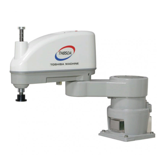
TH850A/TH1050A–IP/TS2100
INSTRUCTION MANUAL
INDUSTRIAL ROBOT SPECIFICATIONS
1.
Make sure that this instruction manual is delivered to the final
user of Toshiba Machine's industrial robot.
2.
Before operating the industrial robot, read through and
completely understand this manual.
3.
After reading through this manual, keep it nearby for future
reference.
DUST- & DRIP-PROOF TYPE
Notice
April, 2009
TOSHIBA MACHINE CO., LTD.
NUMAZU, JAPAN
STE 80765–0
Table of Contents

Related Manuals for Toshiba TH850A


Summary of Contents for Toshiba TH850A
- Page 1 INDUSTRIAL ROBOT SPECIFICATIONS Notice Make sure that this instruction manual is delivered to the final user of Toshiba Machine’s industrial robot. Before operating the industrial robot, read through and completely understand this manual. After reading through this manual, keep it nearby for future reference.
- Page 2 DUST- & DRIP-PROOF TYPE SPECIFICATIONS MANUAL Copyright 2009 by Toshiba Machine Co., Ltd. All rights reserved. No part of this document may be reproduced in any form without obtaining prior written permission from Toshiba Machine Co., Ltd. The information contained in this manual is subject to change without prior notice to effect improvements.
- Page 3 DUST- & DRIP-PROOF TYPE SPECIFICATIONS MANUAL Preface This manual describes the specifications of the TH–A series dust- and drip-proof type industrial robot. This manual is essential to keep the robot performance for a long time, to prevent failures and to assure safety. Be sure to look through this manual and set up a maintenance program before actually starting the robot.
- Page 4 DUST- & DRIP-PROOF TYPE SPECIFICATIONS MANUAL [Explanation of symbols] Symbol Meaning of symbol This means that the action is prohibited (must not be done). Details of the actions actually prohibited are indicated with pictures or words in or near the symbol. This means that the action is mandatory (must be done).
- Page 5 Disassembly prohibited • Always use the Toshiba Machine's designated spare parts when replacing the parts. • Maintenance and inspection should be performed regularly. Otherwise, the system may malfunction or accidents will be Mandatory caused.
- Page 6 DUST- & DRIP-PROOF TYPE SPECIFICATIONS MANUAL This manual is comprised of the following seven (7) sections: Section 1 Specifications This section describes the basic specifications and names of respective parts for the dust- and drip-proof type industrial robot. Section 2 Transportation This section describes how to remove the dust- and drip-proof type robot from its box and how to transport it to the installation site.
-
Page 7: Table Of Contents
DUST- & DRIP-PROOF TYPE SPECIFICATIONS MANUAL Table of Contents Page Specifications ......................9 Name of Each Part ..................9 Outer Dimensions ..................10 Specifications Table..................13 Transportation ......................15 Unpacking......................15 Transportation ....................15 2.2.1 Mass and Outer Dimensions .............16 2.2.2 Transporting the Robot..............18 Installation ......................20 Installation Environment ................20 Ingress Protection (IP) Class of Dust- and Drip-Proof Specification ....21 Air Purge......................22 Coordinate System ..................23... - Page 8 DUST- & DRIP-PROOF TYPE SPECIFICATIONS MANUAL Page Maintenance ......................37 Layout of Robot Components ................37 Maintenance Tools and Provisions ..............38 Replacing Bellows ..................39 5.3.1 Procedures for Replacing Lower Bellows..........39 5.3.2 Procedures for Replacing Upper Bellows..........40 Mounting and Dismounting Covers..............42 5.4.1 Base Cover ..................42 5.4.2 Arm 1 Covers ..................44 5.4.3...
-
Page 9: Specifications
DUST- & DRIP-PROOF TYPE SPECIFICATIONS MANUAL Specifications Name of Each Part The names of respective parts of the dust- and drip-proof type robot are shown in Fig. 1.1 below. (The figure below shows the TH850A robot.) Axis 2 (rotation) Wiring panel... -
Page 10: Outer Dimensions
Fig. 1.2 and Fig. 1.3 show the outer dimensions, and Fig. 1.4 and Fig. 1.5 refer to the operating range of the robot. 配線用パネル Z-axis stroke (340 mm) Z-axis stroke (170 mm) Space required for cable connection Fig. 1.2 Outer dimensions of the robot (TH850A) STE 80765 – 10 –... - Page 11 DUST- & DRIP-PROOF TYPE SPECIFICATIONS MANUAL Wiring panel Z-axis stroke (340 mm) Z-axis stroke (170 mm) Space required for cable connection Fig. 1.3 Outer dimensions of the robot (TH1050A) STE 80765 – 11 –...
- Page 12 DUST- & DRIP-PROOF TYPE SPECIFICATIONS MANUAL Fig. 1.4 Operating range of the robot (TH850A) Fig. 1.5 Operating range of the robot (TH1050A) STE 80765 – 12 –...
-
Page 13: Specifications Table
DUST- & DRIP-PROOF TYPE SPECIFICATIONS MANUAL Specifications Table Item Specifications Structure Horizontal multi-joint type SCARA robot Model TH850A–IP TH1050A–IP Ingress protection (IP) class of IP65 (*1) dust- and drip-proof structure Applicable controller TS2100 (*2) Mass of robot body 77 kg 81 kg No. - Page 14 DUST- & DRIP-PROOF TYPE SPECIFICATIONS MANUAL For details of the IP class, see Para. 3.2. The structure of the robot controller is not dust- and drip-proof. When the mass of load exceeds 2 kg, or when the gravity center position of load is away from the axis 4 center position, both the speed and acceleration should be reduced, using the PAYLOAD command.
-
Page 15: Transportation
The package posture and contents are the same as in the standard robot. See the TH850A/TH1050A Installation and Transportation Manual provided separately. For the dust- and drip-proof type robot, strictly observe the following cautions. -
Page 16: Mass And Outer Dimensions
The mass and outer dimensions of the robot at the time of transport are shown in Fig. 2.1 and Fig. 2.2. Mass of main robot = 77 kg Fixture Fig. 2.1 Outer dimensions at transport (TH850A) STE 80765 – 16 –... - Page 17 DUST- & DRIP-PROOF TYPE SPECIFICATIONS MANUAL Mass of main robot = 81 kg Fixture Fig. 2.2 Outer dimensions at transport (TH1050A) STE 80765 – 17 –...
-
Page 18: Transporting The Robot
The precautions to be taken at transport are stated below. The precautions other than the below are the same as in the standard robot. See the TH850A/TH1050A Installation and Transportation Manual provided separately. (The figure below shows the TH850A robot.) DO NOT hold the bellows. - Page 19 DUST- & DRIP-PROOF TYPE SPECIFICATIONS MANUAL CAUTION • When lifting up the robot by workers, hold the shaded locations by hands, as shown in Fig. 2.3. If the ball screw spline shaft is held by hands, an unusually large force is exerted, resulting in a malfunction. •...
-
Page 20: Installation
DUST- & DRIP-PROOF TYPE SPECIFICATIONS MANUAL Installation Installation Environment Table 3.1 shows the environmental conditions for the location in which the robot and controller are to be installed. Table 3.1 Environmental conditions for robot and controller Item Specifications Temperature In operation 0 to 40°C In storage –10 to 50°C... -
Page 21: Ingress Protection (Ip) Class Of Dust- And Drip-Proof Specification
DUST- & DRIP-PROOF TYPE SPECIFICATIONS MANUAL Ingress Protection (IP) Class of Dust- and Drip-Proof Specification For the dust- and drip-proof specification of TH850A/TH1050A, the ingress protection (IP) class against dust and water is IP65 or equivalent. Be sure to perform air purge. Under some operating environment, water or dust may enter. -
Page 22: Air Purge
DUST- & DRIP-PROOF TYPE SPECIFICATIONS MANUAL Air Purge The dust- and drip-proof type robot is provided with an air supply port for air purge in its base connector unit. See Fig. 1.1. (Quick-operated joint with speed controller) By feeding air into the air supply port, entry of dust into the robot can be prevented. The air supply unit (reducer or pressure reducing valve, air filter, etc.) and air tube (8 mm-dia.) should be provided by the customer. -
Page 23: Coordinate System
Origin of base coordinate system when Z-axis stroke is 170 mm Axis 3 (–) Origin of base coordinate system when Z-axis stroke is 340 mm Fig. 3.1 Base coordinate system and joint angle origin (TH850A) STE 80765 – 23 –... - Page 24 DUST- & DRIP-PROOF TYPE SPECIFICATIONS MANUAL Reference Reference surface surface (–) (–) (–) Axis 4 Axis 2 Axis 1 Origin of base coordinate system when Z-axis stroke is 170 mm Axis 3 (–) Origin of base coordinate system when Z-axis stroke is 340 mm Fig.
-
Page 25: Installing The Robot
When you wish to adjust the robot position in the base coordinate system, or replace the robot with another one, provide appropriate reference surfaces and secure the robot by applying them to the reference surfaces of the base. The base is commonly used by the TH850A and TH1050A robots. CAUTION •... - Page 26 DUST- & DRIP-PROOF TYPE SPECIFICATIONS MANUAL Fig. 3.3 Installation method STE 80765 – 26 –...
-
Page 27: Cable Connection
Cable Connection The connector layout and connection method on the controller side are the same as in the standard robot. See the TH850A/TH1050A Installation and Transportation Manual provided separately. For the dust- and drip-proof type robot, the connector on the robot side differs from that of the standard robot. -
Page 28: Connector Terminal Layout
DUST- & DRIP-PROOF TYPE SPECIFICATIONS MANUAL To connect the connector, make sure of the top and bottom sides of the connector, completely insert the cable side connector into the robot side connector, then lock the lever of the robot side connector. A loose lock can cause a contact failure or other accident. -
Page 29: Tool Interface
DUST- & DRIP-PROOF TYPE SPECIFICATIONS MANUAL Tool Interface Mounting of a tool and tool signals are the same as in the standard robot. For details, see the TH850A/TH1050A Installation and Transportation Manual provided separately. Tool Wiring Five (5) input signals are provided for sensors, etc. and four (4) control signals for solenoid valves, etc. -
Page 30: How To Connect Connectors
DUST- & DRIP-PROOF TYPE SPECIFICATIONS MANUAL Opposite connector type Type of connector: JOEP SMR–07V–B (Maker: J.S.T. Mfg.) JOFP SMR–06V–B (Maker: J.S.T. Mfg.) Type of contact: BYM–001T–0.6 (Maker: J.S.T. Mfg.) JOFP JOEP JOES From PLC, etc. JOFS Motor cover Cable inlet Disconnect. - Page 31 DUST- & DRIP-PROOF TYPE SPECIFICATIONS MANUAL Remove the motor cover of the base unit. For the dust- and drip-proof specification, liquid gasket is coated on the motor cover set surface. For the dismantling procedures, see Section 5. Remove the cap of the cable clamp, then the rubber bushing and filler. This filler is unnecessary and is not used any more.
- Page 32 DUST- & DRIP-PROOF TYPE SPECIFICATIONS MANUAL Input/output signal connector CN0 Signal name Signal Input/output circuit (Cannon and example of connections Not used Customer’s side P24V ● Not used Not used ● GRP1 OPN Grip 1 open GRP1 CLS Grip 1 close ●...
- Page 33 DUST- & DRIP-PROOF TYPE SPECIFICATIONS MANUAL By using the DC24 V power of the controller, a relay, solenoid valve, etc., can be driven. When the external power is used, GND of the external power should be common to GND (PG) of the robot controller. Output specification: Rated voltage DC24 V (max.
- Page 34 DUST- & DRIP-PROOF TYPE SPECIFICATIONS MANUAL Fig. 4.3 Tool wiring STE 80765 – 34 –...
-
Page 35: Tool Air Piping
DUST- & DRIP-PROOF TYPE SPECIFICATIONS MANUAL Tool Air Piping The robot is provided with three (3) air lines for the tool. The outer diameter of the air pipelines is 6 mm. Fig. 4.4 shows the tool air piping. The air control unit (oiler, regulator with gage and filter) and solenoid valves should be provided by the user. - Page 36 DUST- & DRIP-PROOF TYPE SPECIFICATIONS MANUAL Air joint pitches of the panel Fig. 4.4 Tool air piping STE 80765 – 36 –...
-
Page 37: Maintenance
Maintenance The basic structure of the dust- and drip proof type robot is the same as that of the standard robot. For the contents of inspection, etc., see the TH850A/TH1050A Maintenance Manual provided separately. This section deals with the layout of the robot mechanical components and the procedures for replacing the bellows (upper and lower sides) and for mounting and dismounting the covers. -
Page 38: Maintenance Tools And Provisions
DUST- & DRIP-PROOF TYPE SPECIFICATIONS MANUAL Maintenance Tools and Provisions It is recommended to prepare the following items for the maintenance. For the tools and provisions other than the below-mentioned, see the TH850A/1050A Maintenance Manual provided separately. • Screwdrivers (Phillips head screwdriver and slotted screwdriver) •... -
Page 39: Replacing Bellows
DUST- & DRIP-PROOF TYPE SPECIFICATIONS MANUAL Replacing Bellows Replacement of the bellows is performed by our after-sale service engineer. If the bellows is replaced by the customer, we will not guarantee any consequential troubles or accidents. DANGER • Before replacing the bellows with a new one, be sure to turn off the controller power and remove the power plug. -
Page 40: Procedures For Replacing Upper Bellows
This collar is provided only for the machine with 170 mm Z-axis stroke. It is not provided for the machine with 340 mm Z-axis stroke. For how to replace the ball screw, see the TH850A/1050A Maintenance Manual provided separately. STE 80765... - Page 41 DUST- & DRIP-PROOF TYPE SPECIFICATIONS MANUAL When mounting, apply the liquid gasket to this area. Shaft for Gasket Bellows bellows Glued to the upper Lower keep plate keep plate. Gasket Upper keep plate Glued to the Set screw Set screw bearing case.
-
Page 42: Mounting And Dismounting Covers
DUST- & DRIP-PROOF TYPE SPECIFICATIONS MANUAL Mounting and Dismounting Covers A gasket (i.e., rubber packing) is attached to each cover set surface of the dust- and drip-proof type robot. Also, as the liquid gasket is coated to some areas, the mounting and dismounting procedures of each cover differ from those of the standard robot. - Page 43 DUST- & DRIP-PROOF TYPE SPECIFICATIONS MANUAL Folded sections Gasket Cover also serving as connector panel cover Cross-recessed truss head screw (M4x6) Apply the liquid gasket Hexagon socket head throughout this surface. cap screw (M4x6) Fig. 5.4 Cover concurrently used for connector panel When mounting the cover, apply the liquid gasket to the area shown in Fig.
-
Page 44: Arm 1 Covers
DUST- & DRIP-PROOF TYPE SPECIFICATIONS MANUAL Gasket Cover concurrently used for battery box Apply the liquid gasket throughout this surface. Fig. 5.5 Cover concurrently used for battery box When mounting the cover, apply the liquid gasket to the area shown in Fig. 5.5 above. - Page 45 DUST- & DRIP-PROOF TYPE SPECIFICATIONS MANUAL Arm cover 1 Gasket Arm 1 Gasket Arm cover 2 Apply the liquid gasket to the surface for setting the arm 1 (rear side). Apply the liquid gasket Apply the liquid gasket throughout the gap throughout this surface.
-
Page 46: Arm 2 Cover
DUST- & DRIP-PROOF TYPE SPECIFICATIONS MANUAL 5.4.3 Arm 2 Cover Be sure to disconnect the arm 2 cover only while the upper bellows is removed. For how to disconnect the upper bellows, see Para. 5.2.2 above. The arm 2 cover is secured to the cover securing bracket with six (6) cross-recessed truss head screws (M4 ×... - Page 47 DUST- & DRIP-PROOF TYPE SPECIFICATIONS MANUAL DO NOT peel Cover off the liquid gasket. Packing Liquid gasket Peel off, using a Apply the liquid gasket to the full cutter, etc. circumference of this surface Arm 2 body (i.e., the surface from which the liquid gasket was peeled off to Cross section of packing remove the cover).
-
Page 48: Arm 2 Panel Cover
The cover is provided under the arm 2 so that the wiring panel can be mounted. See the TH850A/TH1050A Installation and Transportation Manual provided separately. The cover is secured to the arm 2 with four (4) cross-recessed truss head screws (M4 ×... -
Page 49: Cleaning Robot Body
DUST- & DRIP-PROOF TYPE SPECIFICATIONS MANUAL Cleaning Robot Body To clean and wash the robot body, be sure to use a neutral detergent. Use a soft sponge and waste cloth, and take careful precautions not to cut or scratch the robot body. -
Page 50: Replacement Parts For Maintenance
Machine stroke is 340 The replacement parts for maintenance other than the above are the same as those of the TH850A/TH1050A robot. For details, see the TH850A/TH1050A Maintenance Manual provided separately. • When you wish to purchase the replacement parts for maintenance, make sure of the serial number of the main robot and contact us. - Page 51 DUST- & DRIP-PROOF TYPE SPECIFICATIONS MANUAL APPROVED BY: CHECKED BY: PREPARED BY: STE 80765 – 51 –...