
Summary of Contents for ATS ATS-LV 1000
- Page 1 PRODUCT INSTRUCTION MANUAL Level Controller ATS – LV 1000 PIM - R0 © 2021 AT Systems. All rights Reserved.
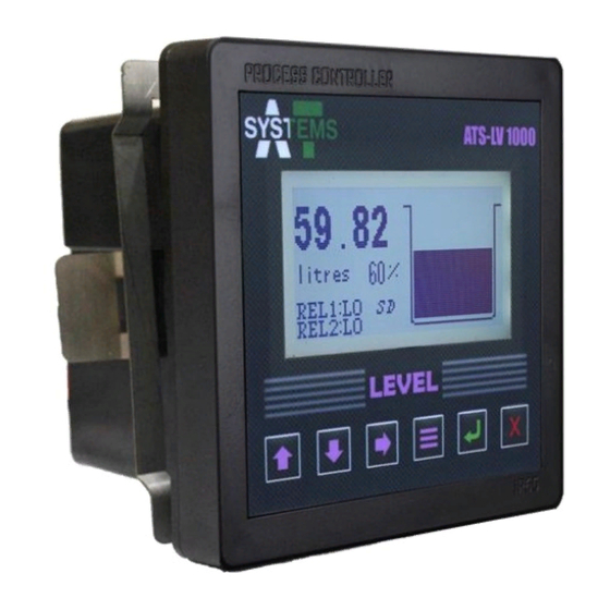
- Page 2 6 control buttons and a 128 x 64 graphics LCD display. This manual explains the use of ATS-LV 1000 controller. This instruction manual is written to cover as many anticipated applications of controller. The information presented in this manual is subject to change without notice as improvements are made.
-
Page 3: Table Of Contents
Table of Contents Section : 1 Introduction General ...................... 1 Features ..................... 1 Specifications ..................... 2 Applications ....................3 Section : 2 Controller Mounting Panel Mounting ..................3 Section : 3 Controller Electrical Connections General Guidelines ..................4 Power ......................4 Transmitter Connection ................ - Page 4 Table of Contents View Date ..................11 7.1.2 Relay 1 Setting ..................11 Relay 1 HI ..................11 Relay 1 LO ..................11 Auto Mode 1 ................. 12 HI Setpoint ..................12 LO Setpoint ..................12 Invert Logic ..................12 Auto Mode 2 ..................
- Page 5 Set Medium SG ................20 Sensor Input .................. 20 7.1.5 SD Card Setting ..................20 Set Interval ................... 21 Save Data ..................21 7.1.6 Select Units ..................21 7.1.7 Device ID ....................21 7.1.8 Calibration ................... 22 7.1.9 Password Setting .................. 22 Change Password .................
-
Page 6: Section : 1 Introduction
If there is evidence of damage, notify the carrier immediately. If parts are missing, contact AT Systems customer support representative. How to enter password? ATS-LV 1000 controller contains built in 4 button password feature which can be customized as per user selection. Press upward button 4 times to insert the default password. Features ATS-LV 1000 controller is designed to be a fully isolated instrument for two-wire DC applications. -
Page 7: Specifications
Specifications Height: Up to 99.999m, 0.001 resolution, ± 0.1% accuracy Measuring Range Volume: Up to 99999m , 0.001 resolution, ± 0.1% accuracy Wide range of tank selection available (cube, cuboid, cylinder, horizontal cylinder and other customized options) Tank Selection with user programmable dimensions Unit selection as per requirement. -
Page 8: Applications
Applications ATS-LV 1000 controller can be used in different industrial applications as mentioned below: • SILO TANKS • UNDERGROUND TANKS • FUEL TANKS • EDIBLE OIL TANKS • DAIRY STORAGE TANKS • OVERHEAD WATER TANKS • DOMESTIC WATER TANKS Section : 2 Controller Mounting... -
Page 9: Section : 3 Controller Electrical Connections
Power A 24 VDC power supply must be used to power the ATS-LV 1000 controller. The exact connection of this power supply is shown in the given image in this section. Always separate input DC power from high power sources, frequency drives, motors or other electrical signal wires which may contribute noise to a system and cause disturbance in reading. -
Page 10: Transmitter Connection
Transmitter Connection Level transmitter cable can be connected to the ATS-LV 1000 controller terminal strip by connecting the transmitter 4 ~ 20mA wires with IN terminals. Make sure that positive and negative connections are connected same on both the devices. Route the signal cable away from AC power wires, frequency drives, motors, or other electrical signal wires. -
Page 11: Relay 1 / 2 Connection
Relay 1 / 2 Connection RIGHT CONNECTOR dataM contains two relay outputs (Relay 1 & Relay 2) which can be connected to the ATS-LV 1000 controller terminal strip by inserting the wires in Relay 1 and Relay 2 connection. • This connection can be used for RELAY function. Connect top (red marked connection) with positive terminal and bottom (blue marked connection) with negative terminal. -
Page 12: Section : 4 Keypad Function
Section : 4 Keypad Function General Guidelines ATS-LV 1000 is simple to control through its 6-buttons control panel. Figure below shows individual keypad buttons with their respective functions: UPWARD / TOP DOWNWARD / BOTTOM FORWARD / RIGHT MENU UPWARD / TOP... -
Page 13: Section : 5 Lcd Display
Section : 5 LCD Display General Guidelines ATS-LV 1000 is easy and clear to view through its large graphical LCD (128 x 64) with adjustable contrast and adjustable backlight. Figure below shows the display icons with their respective description: PARAMETERS VALUE... -
Page 14: Section : 6 Initial Setup
Section : 6 Initial Setup Startup Before performing startup, some prerequisites are necessary. Firstly, ensure the transmitter wires are connected properly to the ATS-LV 1000 controller. Make sure to check the clamping of controller with panel plate. Menu Tree Before performing any operation kindly see the below sequential tree chart for quick access Menu. -
Page 15: Section : 7 Sequential Functions Setup
Section : 7 Sequential Functions Setup Main Menu ATS-LV 1000 controller has an interactive main menu which has nine sub menus and their corresponding Minor Sub Menus. Main Screen Insert Password No default password (See section: 1.1) Main Menu will appear on the Screen. Main Menu has... -
Page 16: C View Time
View Time User can view customized time from this menu. Menu Button Insert Password Enter Button Set Time / Date Enter Button Downward Button View Time View time will appear and can be selected. Time customized will show up in hours and minutes. View Date User can view customized date from this menu. -
Page 17: C Auto Mode 1
Auto Mode 1 This sub menu can be used for Auto operation of Relay 1. User can select relay 1 setting on auto mode from this sub menu. This relay will operate based on HI Setpoint and LO Setpoint values inserted by user. When the analogue input value rises from HI setpoint value, then Relay 1 will turn ON. -
Page 18: G Auto Mode 2
Auto Mode 2 This sub menu can be used for time-based auto operation of Relay 1. User can select relay 1 setting on auto mode from this sub menu. This relay will operate based on turn on time and turn off time inserted by user. -
Page 19: Relay 2 Setting
Relay 2 HI This sub menu can be used for manual operation of Relay 2. User can turn ON relay 2 manually from this sub menu. Menu Button Insert Password Downward Button Enter Button Relay 2 Setting Enter Button Relay 2 HI Relay 2 LO This sub menu can be used for manual operation of Relay 2. -
Page 20: Elo Setpoint
LO Setpoint User can select relay 1 low setpoint percentage value between 0 to 100 % depending on the 4~20mA input the level controller is receiving. This value should be less than LO setpoint otherwise controller will not accept the value. Menu Button Insert Password Downward... -
Page 21: I Turn Off Time
Turn OFF Time This sub menu can be used for time-based auto operation of Relay 2. User will have to insert its required relay turn OFF time mentioning hours and minutes. Use upward or downward button to select required digit form 0-9 and forward button to switch between hours and minutes. -
Page 22: B Cuboid
Cuboid User can select cube tank shape using this menu. Note: Make sure to select the correct shape of tank otherwise controller will not calculate and display the volume accurately. Menu Button Insert Password Downward Button Tank Setting Enter Button Downward Button Cuboid Enter Button... -
Page 23: D Dairy Tank
Dairy Tank User can select dairy tank shape using this menu. Note: Make sure to select the correct shape of tank otherwise controller will not calculate and display the volume accurately. Menu Button Insert Password Downward Button Tank Setting Enter Button Downward Button Dairy Tank Enter Button... -
Page 24: F Set Dimensions
Set Dimensions User can input dimensions of selected tank using this menu. First make sure to select proper shape of tank than select set dimensions. Each tank shape has its own set dimensions option. Units required for dimensions input are in meters. •... -
Page 25: G Set Medium Sg
Enter Button Downward Button Sensor Input Enter Button 7.1.5 SD Card Setting ATS-LV 1000 has a built in removable 2GB SD card storage. User can define SD card settings from this menu. Menu Button Insert Password Downward Button SD Card Setting This setting contains two sub menus as Set Interval, Save Data and Clear SD Card. -
Page 26: A Set Interval
User can select any units from following: CUBIC METER, LITRE, GALLON 7.1.7 Device ID ATS-LV 1000 contains device ID option. Device ID is used for communication between Level Controller and Level Controller Software. This communication is based on RS485. Menu Button... -
Page 27: Calibration
7.1.8 Calibration User can calibrate analogue input values for level controller using this menu. A general 4~20mA calibrator will auto calibrate the reference values. 4mA option shows the Low Value of calibration and 20mA option shows the High Value of calibration. Note: Make sure to check the values of calibration are same as shown by the calibrator. -
Page 28: Section : 8 Troubleshooting
Section : 8 Troubleshooting General Guidelines This section informs the user how to quickly resolve an operational problem with the system. During any troubleshooting phase, it will save time if the operator can firstly determine the problem. Either it is related to the process controller, process sensor, or some external source. Therefore, this section is organized from the approach of excluding any likely external sources, isolating the controller and finally isolating the sensor. -
Page 29: Field Mounting Parts
Field Mounting Parts Controller is already assembled in IP65 panel mount enclosure for dust and water protection. For field mounting, AT Systems can also provide IP67 field mount enclosure with installed cable glands for cables connection. Field enclosure also contains the through hole of lock for protection from unknown users’... -
Page 30: Section : 10 Technical Drawings
Section : 10 Technical Drawings 10.1 Controller Dimensions ATS-LV 1000 controller technical detailed dimensions can be seen below: Notes: This dimensional drawing is not to scale. All dimensions are in mm [inches]. 25 / 26... -
Page 31: Exploded View
10.2 Exploded View ATS-LV 1000 controller exploded view can be viewed below: SIDE CLAMP PLATE FRONT PART CONTROLLER BACK PART GASKET SCREWS FRONT PART INCLUDES LCD AND CONTROLLER BUTTONS PCB. BACK PART INCLUDES POWER SUPPLY PCB, MAIN PCB AND CONNECTORS. - Page 32 24-A-10 SECTOR B1, TOWNSHIP, LAHORE, PAKISTAN. POSTAL CODE: 54770 Tel: +92 300 064 54 54 ATS – LV 1000 PIM - R0 Web: www.atsystems.com.pk © 2021 AT Systems. All rights Reserved Email: [email protected]...