Table of Contents
Quick Links
Table of Contents

Summary of Contents for GE Baker Hughes LUMEN TERRAIN
- Page 1 LUMEN TERRAIN User’s Manual [Preliminary Draft 02] bhge.com 910-328 Rev. A...
- Page 2 May 2019...
-
Page 3: Chapter 1 Table Of Contents
Contact your BHGE representative for the most current information. The Baker Hughes logo is a trade mark of Baker Hughes, a GE company. The GE Monogram is a trademark of the General Electric... - Page 4 [no content intended for this page]...
-
Page 5: Table Of Contents
Contents Chapter 1 Table of Contents Chapter 1 Table of Contents ........................3 Product Registration ....................................5 Services ........................................5 Typographical Conventions ................................... 5 Safety Issues ....................................... 5 Auxiliary Equipment ....................................8 Local Safety Standards .................................. 8 Working Area....................................8 Qualification of Personnel ................................ - Page 6 Contents 2.5.1.Sensor Node Enclosure Installation ........................25 2.5.2.Sensor Node Solar Panel............................... 26 2.5.3.Sensor Node Conduit Wiring Connection ......................27 2.5.3.1. Battery and Solar Panel Wiring, Enclosure ..................... 28 2.5.4.Antenna Installation ..............................29 2.5.5.Battery and Solar Panel Wiring ..........................30 Chapter 3 . Software Initialization ...................... 30 3.1.
-
Page 7: Product Registration
Preface Product Registration Thank you for purchasing Lumen Terrain from BHGE. Please register your product at www.gemeasurement.com/productregistration for product support such as the latest software/firmware upgrades, product information and special promotions. Services BHGE provides customers with an experienced staff of customer support personnel ready to respond to technical inquiries, as well as other remote and on-site support needs. -
Page 8: Auxiliary Equipment
Preface Auxiliary Equipment Local Safety Standards The user must make sure that he operates all auxiliary equipment in accordance with local codes, standards, regulations, or laws applicable to safety. Working Area WARNING! Auxiliary equipment may have both manual and automatic modes of operation. As equipment can move suddenly and without warning, do not enter the work cell of this equipment during automatic operation, and do not enter the work envelope of this equipment during manual operation. -
Page 9: Product Security
Preface Product Security The customer shall provide adequate physical site security measures to protect the Lumen Terrain Sensor Nodes, Base Station, and supporting hardware (antennas, solar panels, weather station, etc.) from damage due to vandalism, airborne debris, theft, security breaches. Lumen Terrain provides data encryption to protect customer data from intentional snooping that is transmitted via the RF over the air interfaces (between base station and sensor node and between the base station and cloud). -
Page 10: Environmental Compliance
Preface Environmental Compliance RoHS The Sensor Solutions Lumen-Terrain fully complies with RoHS regulations (Directive 2002/95/EC). Waste Electrical and Electronic Equipment (WEEE) Directive BHGE is an active participant in Europe’s Waste Electrical and Electronic Equipment (WEEE) take-back initiative (Directive 2012/19/EU). The equipment has required the extraction and use of natural resources for its production. It may contain hazardous substances that could impact health and the environment. -
Page 11: Fcc Statements
Preface FCC Statements In order to comply with FCC / ISED RF Exposure requirements, this device must be installed to provide at least 20 cm separation from the human body at all times. “Afin de se conformer aux exigences d'exposition RF FCC / ISED, cet appareil doit être installé pour fournir au moins 20 cm de séparation du corps humain en tout temps.“... - Page 12 Preface ISED Canada ICES-003 Compliance Label “CAN ICES-3 (B)/NMB-3(B)” Base Station FCC ID: 2ATKJ-LTBS IC: 24840-LTBS Contains FCC ID: N7NMC7455 and Contains IC: 2417C-MC7455 Sensor Node FCC ID: 2ATKJ-LTSN IC: 24840-LTSN LUMEN TERRAIN User Manual...
- Page 13 Preface [no content intended for this page] LUMEN TERRAIN User Manual...
-
Page 14: Chapter 1 . Introduction
Chapter 2. Installation Chapter 1 . Introduction 1.1. Overview Fugitive methane emissions reduction is one of the most pressing needs in the Oil & Gas industry today. Traditional measurement practices are often inaccurate and inefficient – putting you at risk of dangerous, damaging and costly leaks. -
Page 15: Installation Guidelines
Chapter 2. Installation 2.1.Installation Guidelines This section provides general information with respect to the mechanical and electrical installation, and should be thoroughly reviewed before the system is installed. To ensure safe and reliable operation of the LUMEN TERRAIN, the system must be installed in accordance with the established guidelines per application engineering drawing. -
Page 16: Unpacking The Lumen Terrain System
Please inspect the Base Station, Sensor Nodes, and Solar panels upon receiving the package. Each instrument manufactured by Sensor Solutions from Baker Hughes, a GE company is warrantied to be free from defects in material and workmanship. Before discarding any of the packing materials, account for all components and documentation listed on the packing slip. -
Page 17: Base Station Installation
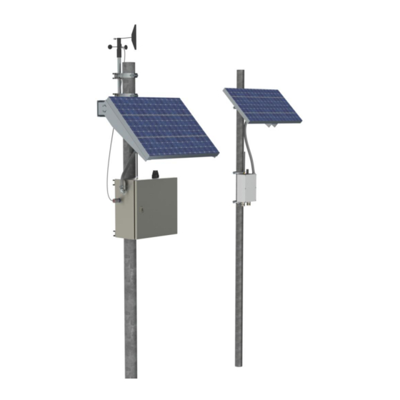
Chapter 2. Installation 2.4. Base Station Installation This section will guide you through the installation of the Base Station enclosure, solar panel, weather station, and necessary electrical connections. CAUTION! The Base Station weighs 52lbs and requires two people to lift and install. 2.4.1. -
Page 18: Solar Panel Installation
Chapter 2. Installation 2.4.2. Solar Panel Installation The solar panel is to be installed at a height close to 87 inches measured from the top of the solar panel to the base of the pole. To assemble the solar panel bracket and attach the solar panel, see Figure 2. The orientation of the bracket will depend on location of the site. -
Page 19: Weather Station
Chapter 2. Installation 2.4.3. Weather Station The weather station should be mounted last due to its fragility. It is to be mounted at a height above the solar panel bracket mounts. Assemble the Weather Station mounting brackets to the pole and weather station. Install the Weather Station the pole as shown in Figure 4 and torque the nuts to 6 ft-lbs. - Page 20 Chapter 2. Installation To attach the right-angle conduit adapter to the base station enclosure, loosen Item 1 from Item 5 so they are disconnected as shown in the figure above. Note that Items 3 and 4 should already be attached to the conduit as shown. Ensure Item 4 is fully inserted by turning it clockwise until there is no more movement.
-
Page 21: Wiring Connection, Enclosure
Chapter 2. Installation The finished assembly should look similar to the following figure. Note that the orientation of Item 2 may be different. Figure 8: Finished Right Angle Conduit Connection 2.4.4.1. Wiring Connection, Enclosure On the Base Station enclosure end, connect the red cable from the conduit to the ‘+’ terminal of the Solar Panel Connection on the PCB and connect the black cable from the conduit to the ‘-‘... -
Page 22: Wiring Connection, Solar Panel
Chapter 2. Installation Remove Item 1 from Item 4. Items 2 and 3 should be already installed in the conduit but check to see if Item 3 is secure by turning it clockwise. Remove the lock nut (Item 6) and insert Item 4 into knockout created previously with Item 5 sitting on the outside of the solar panel junction box. -
Page 23: Antenna Installation
Chapter 2. Installation Figure XXX: Solar Panel Wiring Connection 2.4.6. Antenna Installation Due to the length of the Sub-1G antenna, the antenna does not come installed on the Base Station. Remove the protective cap on top of the Base Station enclosure and torque the supplied Sub-1G antenna on the exposed bulkhead to 5 in-lbs as shown in Figure 10. -
Page 24: Weather Station Wiring
Chapter 2. Installation 2.4.7. Weather Station Wiring Insert the weather station cables into the gray plastic adapter and wire the colored wires corresponding to the labels found on the screw terminal as shown in 11. Figure 11: Weather Station Wiring Connection 2.4.8. -
Page 25: Sensor Node Installation
Chapter 2. Installation 2.5. Sensor Node Installation This section will guide you through the installation of the Node enclosure, solar panel, weather Sensor station, and necessary electrical connections. 2.5.1. Sensor Node Enclosure Installation After a pole with the requirements mentioned in Section 2.3.1.2 is installed or located, the Sensor Node enclosure can be mounted. -
Page 26: Sensor Node Solar Panel
Chapter 2. Installation 2.5.2. Sensor Node Solar Panel Install the Node solar panel on the pole at a height close to 90 inches measured from the Sensor top of the solar panel to the base of the pole. Assemble the Node solar panel mounting bracket parts and attach the Node solar Sensor... -
Page 27: Sensor Node Conduit Wiring Connection
Chapter 2. Installation Figure 15: Solar Panel Assembly Pole Mount 2.5.3. Sensor Node Conduit Wiring Connection Refer to the following figure for Item callouts: Figure 16: Sensor Node Right Angle Adapter Item Callouts LUMEN TERRAIN User Manual... -
Page 28: Battery And Solar Panel Wiring, Enclosure
Chapter 2. Installation Remove Item 1 from Item 3 along with the red and black cables. Remove Item 5 from Item 3 and insert that end into the open hole of the Sensor Node enclosure such that Item 4 is on the outside of the enclosure as shown above. -
Page 29: Antenna Installation
Chapter 2. Installation Figure XXX: Battery and Solar Panel Wiring Connections. 2.5.4. Antenna Installation Due to the length of the Sub-1G antenna, the antenna does not come installed on the Base Station. Simply remove the protective cap on top of the Base Station enclosure and torque the supplied Sub-1G antenna on the exposed bulkhead to 5 in-lbs as shown in the following figure. -
Page 30: Battery And Solar Panel Wiring
Chapter 2. Installation Figure 17: Sensor Node Antenna Installation 2.5.5. Battery and Solar Panel Wiring Chapter 3 . Software Initialization 3.1. 3.1.1. 3.1.1.1. TBD 3.2. 3.3. 3.4. LUMEN TERRAIN User Manual... -
Page 31: Chapter 4 . Spare Parts
Chapter 2. Installation Chapter 4 . Spare Parts This section lists all the spare parts for the Lumen system if troubleshooting procedures has indicated a hardware failure. 4.1. Base Station Spare Parts Table 1: Base Station Spare Parts BHGE PN Description Picture 126M6391... -
Page 32: Sensor Node Spare Parts
Chapter 2. Installation 132M5508 5A Fuse 4.2. Sensor Node Spare Parts Table 2: Sensor Node Spare Parts BHGE PN Description Picture 129M4502 Sensor Node Assembly 130M1103 30W Solar Panel 128M5166 9V Battery 130M9040 Sub 1G Antenna LUMEN TERRAIN User Manual... -
Page 33: Appendix A: Torque Specifications
Chapter 2. Installation Appendix A: Torque Specifications A.1. Base Station Table 3: Base Station Torque Specifications Component Torque Exterior Sub-1G Antenna 5-5.25 in-lbs (56-59 cNm) Sierra Wireless Antenna 54-57 in-lbs (610-644 cNm) Solar Panel Adapter (locknut) 1 turn pass hand-tight Solar Panel Adapter (conduit) 1.5 turns pass hand-tight Right Angle Adapter (locknut) -
Page 34: Warranty
Warranty Warranty Each instrument manufactured by Panametrics flow meter from Baker Hughes, a GE company is warranted to be free from defects in material and workmanship. Liability under this warranty is limited to restoring the instrument to normal operation or replacing the instrument, at the sole discretion of Panametrics & Panametrics Flow meter. - Page 35 Warranty [no content intended for this page] LUMEN TERRAIN User Manual...
- Page 36 Warranty LUMEN TERRAIN User Manual...
- Page 37 Contact your BHGE representative for the most current information. The Baker Hughes logo is a trade mark of Baker Hughes, a GE company. The GE Monogram is a trademark of the General Electric Company.