Acer P1200 Service Manual
Hide thumbs
Also See for P1200:
- User manual (63 pages) ,
- User manual (75 pages) ,
- User manual (63 pages)

Related Manuals for Acer P1200


Summary of Contents for Acer P1200
-
Page 1: Service Manual
SERVICE MANUAL P1100C/P1200i/P1200B Date Revise Version Description 2010.04.29 V1.0 Initial Issue Copyright Apr. 2010 All Rights Reserved Prepared: Check: Approved:... - Page 2 P1100C/P1200i/P1200B Comparison List Parts Main Board 70.8GG23GR01 IO Cover 70.8GG24GR01 Top Cover Engine Module DMD Chip IO Board 80.8GG06G001 Antenna 75.8BA07G002 P1200i P1200B 70.8GG30GR01 70.8GG31GR01 70.8GG25GR01 70.8GG20GR01 48.8CQ01G003 80.8GG06G011 P1100C/P1200i/P1200B Confidential P1100C 70.8GF37GR01 70.8GF38GR01 70.8GF39GR01 70.8GF26GR01 48.8EH01G001 80.8GF06G001...
- Page 3 Preface This manual is applied to P1100C/P1200i/P1200B projection system. The manual gives you a brief description of basic technical information to help in service and maintain the product. Your customers will appreciate the quick response time when you immediately identify problems that occur with our products.
-
Page 4: Table Of Contents
Table of Content Chapter 1 Introduction Highlight Compatible Mode Product Overview Chapter 2 Disassembly Process & Assembly Process Equipment Needed & Product Overview Disassemble Lamp Module Disassemble Top Cover Module Disassemble Keypad Board Module and Zoom Ring Module 2-4 Disassemble Main Board Module and IO Board Disassemble Front Cover Module Disassemble Color Wheel Module Disassemble Engine Module... - Page 5 Assemble System Fan Module and the Blower Module Assemble DMD Chip and DMD Board Assemble Engine Module Assemble Color Wheel Module Assemble Front Cover Module Assemble Main Board Module and the Blower Module Assemble Keypad Board Module and Zoom Ring Assemble Top Cover Module Assemble Lamp Module Chapter 3...
- Page 6 Wireless Function Test Others Chapter 5 Firmware Upgrade Section 1: System Firmware Upgrade Equipment Needed DLP Composer Lite Setup Procedure Get into FW Download Mode USB Driver Upgrade Procedure Section 1: Firmware Upgrade Procedure Section 2: Network FirmWare Upgrade Section 3: Waveform Download Chapter 6 EDID Upgrade EDID Introduction...
-
Page 7: Chapter 1 Introduction
Chapter 1 Introduction 1-1 Highlight Item Dimensions (W x H x D) Weight Tilt Angle Power Supply Keystone correction Cooling system Throw ratio � Projection lens Brightness Contrast �ni�ormity Description ● 269x205.6x95.5mm ● <3 kg ● 7 degree with elevator mechanism ●... - Page 8 Item �amp li�e �3 System controller TI D��D �5 ��umber o� active dots �6 Color wheel �7 �amp �� ��ideo compatibility Description ● �000 hours, 50% survival rate (�ull power ��ode) ● 5000 hours, 50% survival rate (�co power ��ode) 5000 hours, 50% survival rate (�co power ��ode) ●...
- Page 9 Item �9 Terminal Input signal spec. Description ● HD��I �.3*�: Support HD��I video/audio and graphic signal (�or P�200i/P�200B) ● ��GA In * �: �ne D�Sub �5�Pin �emale Connector �or PC input and analog Data ( Component i/p, HDT��, �GB Sync) (�or P�200i/P�200B) ��GA In * 2 (�or P��00C) ●...
-
Page 10: Compatible Mode
1-2 Compatible Mode Computer Compatibility A. VGA Analog Modes Resolution (1) VGA Analog - PC Signal ��GA 6�0x��0 6�0x��0 6�0x��0 6�0x��0 6�0x��0 S��GA �00x600 �00x600 �00x600 �00x600 �00x600 �00x600 �02�x76� �02�x76� �02�x76� �02�x76� �02�x76� SXGA ��52x�6� ��52x�6� ��52x�6� �2�0x�02� �2�0x�02� �2�0x�02�... - Page 11 Modes Resolution i ��ac D��(G3) �02�x76� (2) VGA Analog - Extended Wide timing WXGA �2�0x76� �2�0x76� �2�0x76� �2�0x720 �2�0x�00 ���0x900 �6�0x�050 �366x76� �920x�0�0 �02�x600 (3) VGA Analog -Component Signal ��0i 720x��0 ��0p 720x��0 576i 720x576 576p 720x576 720p �2�0x720 720p �2�0x720 �0�0i �920x�0�0...
- Page 12 B. HDMI Digital Modes Resolution (1) HDMI - PC Signal (same as DVI) ��GA 6�0x��0 6�0x��0 6�0x��0 6�0x��0 6�0x��0 S��GA �00x600 �00x600 �00x600 �00x600 �00x600 �00x600 �02�x76� �02�x76� �02�x76� �02�x76� SXGA ��52x�6� ��52x�6� �2�0x�02� �2�0x�02� �2�0x�02� �2�0x�02� Quad��GA �2�0x960 PowerBook G� 6�0x��0 PowerBook G�...
- Page 13 Modes Resolution �2�0x�00 ���0x900 �6�0x�050 �366x76� �920x�0�0��IA �02�x600 (3) HDMI - Video Signal 720x��0 ��0i (���0x��0) ��0p 720x��0 720x576 576i (���0x576) 576p 720x576 720p �2�0x720 720p �2�0x720 �0�0i �920x�0�0 �0�0i �920x�0�0 �0�0p �920x�0�0 �0�0p �920x�0�0 V.Frequency [Hz] H.Frequency [KHz] 59.9� (29.97) 59.9�...
-
Page 14: Product Overview
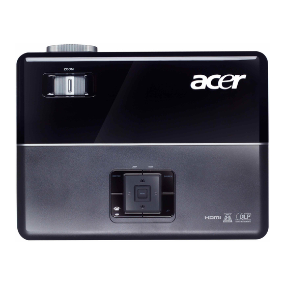
1-3 Product Overview Projector Outlook Front /Upper side Item Description Control panel ��entilation (inlet) ��entilation (outlet) �levator button �levator �oot Item Description Zoom lever �emote control receiver � �ocus ring Zoom lens �ens cap P1100C/P1200i/P1200B Confidential ���... -
Page 15: Rear Side
Rear side P1100C/P1200i/P1200B Confidential ��9... - Page 16 Item Description �SB connector Power socket S���ideo input connector Composite video input connector ��onitor loop�through output connector (��GA��ut) PC analog signal/HDT��/component video input connector Audio input connector � �S232 connector KensingtonT�� lock port �A�� (�J�5 Port �or �0/�00�� �thernet) Item Description Audio output connector �SB connector (mini B Type)
-
Page 17: Control Panel
See the contents in “Turning the Projector �n/���” section. Temp Indicator ��D �se to select items or make adjustments to your selection. Press “S���C�” to choose �GB, Component, S��ideo, Composite, SCA�T, HDT�� and HD��I™ sources. �nique Acer �unctions: e�pening, e��iew, eTimer, ePower ��anagement. P1100C/P1200i/P1200B Confidential 1-11... -
Page 18: Remote Control Layout
Remote Control Layout P1100C/P1200i/P1200B Confidential 1-12... - Page 19 Aim the remote at the viewing screen, press and hold this button to activate the laser pointer. This �unction is not supported in Japanese market. �nique Acer �unctions: e�pening, e��iew, eTimer, ePower ��an- agement. Adjusts the image to compensate �or distortion caused by tilting the projector (±...
- Page 20 Item Function C���P������T S���ID�� ��ID�� SD/�SB A HD��I™/D��I �SB B �A��/Wi�i KeyPad 0~9 �our directional 2� select keys Note: “#”Japan area is not supported “*” No DVI function Description ��o C���P������T �unction. Press “S���ID��” to change source to S���ideo. Press “��ID��” to change source to composite video. Press “SD/�SB A”...
-
Page 21: Getting Started
Getting Started Connecting the Projector Item Description Power cord �SB cable HD��I cable S���ideo cable Composite video cable ��GA cable ��GA to component/HDT�� adapter Note: To ensure the projector works well with your computer, please make sure the timing of the display mode is compatible with the projector. Item Description �... - Page 22 System Block Diagram P1100C/P1200i/P1200B Confidential ���6...
- Page 23 Bottom Cover Dimension P1100C/P1200i/P1200B Confidential ���7...
-
Page 24: Equipment Needed & Product Overview
Chapter 2 Disassembly & Assembly Process 2-1 Equipment Needed & Product Overview 1. Screw Bit (+): 105 2. Screw Bit (+): 107 3. Screw Bit (-): 107 4. Hex Sleeves 5mm 5. Long Nose Nipper 6. Tweezers 7. Projector * Before you start: This process is protective level II. Operators should wear electrostatic chains. * Note: - If you need to replace the Main Board, you have to get into Service Mode and record the lamp usage hour, please refer to section 2-16. -
Page 25: Disassemble Lamp Module
2-2 Disassemble Lamp Module 1. Unscrew 1 screw (as red circle). 2. Push forward the Lamp Cover Moudle (as yellow arrows) on the left/right side of the projector. 3. Pull upward the Lamp Cover Module (as blue arrows point). 4. Loosen 2 screws (as red circle) on the Lamp Module. -
Page 26: Disassemble Top Cover Module
2-3 Disassemble Top Cover Module 1. Unscrew 6 screws (as red circle) from the Top Cover. 2. Pull upward the Top Cover Module. Note: - When you disassemble the Top Cover, take care the FPC cable which connect Main Board and Keypad Board Module. - Page 27 2-4 Disassemble Keypad Board and Zoom Ring 1. Tear off the Maylar (as green square) and unplug the FPC Cable. 2. Unscrew 4 screws (as red circle) to disassemble the Keypad Board Module. 3. Separate the Keypad Board and Keypad Module.
-
Page 28: Disassemble Main Board Module And Io Board
2-5 Disassemble Main Board Module and IO Board 1. Unscrew 5 screws (as red circle) to disassemble the Main Board Top Shielding. 2. Unscrew 4 hex screws (as green circle). 3. Unscrew 3 screws (as red circle). P1100C/P1200i/P1200B Confidential... - Page 29 4. Unplug 7 connectors (as yellow square). Unplug 7 connectors (as yellow square). 5. Unplug 2 connectors (as purple square). Unplug 2 connectors (as purple square). Please refer to the table as below for details about each connector. Male Connector Item on Main Board Photo Sensor...
- Page 30 Male Connector Item on Main Board Lamp Driver Speaker 6. Unscrew 1 hex screw (as red circle) Unscrew 1 hex screw (as red circle) The key feature Black wire tube (5 pin) Compose of Yellow/White wire and Black wire tube (2 pin) P1100C/P1200i/P1200B Confidential Figure...
- Page 31 7. Unscrew 3 hex screws (as red circle) to Unscrew 3 hex screws (as red circle) to Separate IO Board and MB Module. IO Board Main Board Module NOTE: Circuit boards > 10 cm² has been highlighted with the yellow rectangle as above image shows.
-
Page 32: Disassemble Front Cover Module
2-6 Disassemble Front Cover Module 1. Unscrew 1 screw (as yellow circle). 2. Disassemble the Front Cover Module. 3. Tear off black mylar (as yellow square) form IR Board. 4. Disassemble IR Board. IR Board P1100C/P1200i/P1200B Confidential... -
Page 33: Disassemble Color Wheel Module
2-7 Disassemble Color Wheel Module 1. Unscrew 2 screws (as yellow circle). 2. Remove the Color Wheel Module. Remove the Color Wheel Module. 3. Unscrew 1 screw (as green circle). 4. Separate the Photo Sensor Board and Color Wheel. Note: - Avoid touching the glass parts of Color Wheel. -
Page 34: Disassemble Engine Module
2-8 Disassemble Engine Module 1. Unscrew 4 screws (as yellow circle) to disassemble the Engine Module. 2. Take off the Main Broad Spacer . 2-9 Disassemble DMD Chip and DMD Board 1. Tear off the black heatsink mylar (as red square). - Page 35 3. Unscrew 2 screws (as blue circle). 4. Disassemble the Heat Sink and DMD Module. 5. Rotate the screw (as yellow circle) 180° counterclockwise to disassemble the DMD Board and DMD Chip. Note: - Avoid touching the DMD Chip when you disassemble it.
-
Page 36: Disassemble System Fan Module And The Blower Module
2-10 Disassemble System Fan Module and the Blower Module 1. Unscrew 3 screws (as red circle) to disassemble System Fan Module. 2. Unscrew 4 screws (as red circle) to separate System Fan and Fan Shielding. System Fan P1100C/P1200i/P1200B Confidential Fan Shielding 2-1... - Page 37 Note: - Take the Fan Module as the right gesture. 3. Unscrew 3 screws (as yellow circle) to disassemble the Blower Module. 4. Separate the Blower Rubber and the Blower. the right gesture P1100C/P1200i/P1200B Confidential the wrong gesture 2-1...
-
Page 38: Disassemble Lamp Driver Module And Interrupt Switch And Speaker
2-11 Disassemble Lamp Driver Module and Interrupt Switch and Speaker 1. Take the Interrupt Switch off and Unplug 2 connectors (as red square). note: Loosen the hook on the Lamp Driver. (as red circle) 2. Unscrew 1 screw (as green circle) to disassemble the Lamp Driver Module. -
Page 39: Disassemble Lvps Module
6. Unscrew 1 screw (as red circle). 7. Separate Speaker and Speaker Bracket. 2-12 Disassemble LVPS Module 1. Unscrew 6 screws (as red circle) to disassemble the LVPS Module. 2. Unplug 1 connector (as green square). 3. Remove the cable and the AC Inlet Bracket from LVPS Module. -
Page 40: Disassemble Bottom Shielding And Io Cover Module
2-13 Disassemble Bottom Shielding and IO Cover Module 1. Unscrew 2 screws (as red circle) to disassemble bottom shielding. 2. Unfasten 2 tenons (as green rectangle) to disassemble IO Cover. P1100C/P1200i/P1200B Confidential 2-17... -
Page 41: Disassemble Elevator Foot Rubber
2-14 Disassemble Elevator Foot Rubber 1. Turn over the bottom cover, then take off the Elevator Foot Rubber (as red rectangle). P1100C/P1200i/P1200B Confidential 2-1... -
Page 42: Rod Adjustment
2-15 Rod Adjustment 1. Environment Adjustment - The distance between the engine and the screen is 2.38M. - This process should be done at a dark environment (under 2 Lux). 2. Procedure Adjustment - Change the screen to "white screen". - Adjust the screws by using the rod on the engine module to re-adjust the image. -
Page 43: Re-Write System And Lamp Usage Hour
2-16 Re-write System and Lamp Usage Hour 1. Get into Service Mode - Press "Power", "Left", "Left" and "Menu" buttons sequentially to get into Service Mode. 2. Get into Other Settings Mode - Use "Up" or "Down" buttons to select "Other Settings", then press "Menu"... -
Page 44: Assemble Elevator Foot Rubber
2-17 Assemble Elevator Elevator Foot Rubber 1. Assemble the Elevator Foot Rubber (as red rectangle). 2-18 Assemble Bottom Shielding and IO Cover Module 1. Fasten 2 tenons (as green rectangle) to assemble IO Cover. P1100C/P1200i/P1200B Confidential 2-21... -
Page 45: Assemble Lvps Module
2. Screw 2 screws (as red circle) to assemble bottom shielding. 2-19 Assemble LVPS Module 1. Fixed the AC Inlet Bracket on LVPS Module. 2. Plug 1 connector (as green square). 3. Screw 6 screws (as red circle) to assemble the LVPS Module. P1100C/P1200i/P1200B Confidential AC Inlet Bracket 2-22... -
Page 46: Assemble Lamp Driver Module And Interrupt Switch And Speaker
2-20 Assemble Lamp Driver Module and Interrupt Switch and Speaker 1. Assemble the Speaker and the Speaker Bracket. 2. Screw 1 screw (as red circle) to assemble the speaker module. 3. Assemble the Lamp Driver Module and the Lamp Driver Holder. 4. -
Page 47: Assemble System Fan Module And The Blower Module
6. Screw 1 screw (as green circle) to assemble the Lamp Driver Module. 7. Plug 2 connectors (as red square) on LVPS Module. 8. Fasten 1 tenon(as red circle) to assemble the Interrupt Switch. 2-21 Assemble System System Fan Module and the Blower Module 1. - Page 48 3. Screw 4 screws (as red circle) to assemble System Fan and Fan Shielding. 4. Screw 3 screws (as red circle) to assemble System Fan Module. System Fan P1100C/P1200i/P1200B Confidential Fan Shielding 2-25...
-
Page 49: Assemble Dmd Chip And Dmd Board
2-22 Assemble DMD Chip and DMD Board 1. Rotate the screw (as yellow circle) 180° clockwise to assemble the DMD Board and DMD Chip. 2. Assemble the Heat Sink and DMD Module. 3. Screw 2 screws (as blue circle). 4. Screw 3 screws (as red circle) to assemble the focus ring. -
Page 50: Assemble Engine Module
2-23 Assemble Engine Module 1. Place the Main Broad spacer. 2. Screw 4 screws (as yellow circle) to assemble the Engine Module. 2-24 Assemble Color Wheel Module 1. Assemble the Photo Sensor Board and Color Wheel. 2. Screw 1 screw (as green circle). P1100C/P1200i/P1200B Confidential Main Broad Spacer 2-27... -
Page 51: Assemble Front Cover Module
3. Screw 2 screws (as yellow circle) to assemble the color wheel module. Note: - Avoid touching the glass parts of Color Wheel. 2-25 Assemble Front Cover Module 1. Assemble IR Board on Front Cover. 2. Stick black mylar (as yellow square) on IR Board. - Page 52 3. Assemble the Front Cover Module. 4. Screw 1 screw (as yellow circle). P1100C/P1200i/P1200B Confidential 2-2...
- Page 53 2-26 Assemble Main Board Module and IO Board 1. Screw 3 hex screws to disassemble Screw 3 hex screws to disassemble IO Board on Main Board. 2. Screw 1 hex screw (as red circle) Screw 1 hex screw (as red circle) Main Board Module P1100C/P1200i/P1200B Confidential IO Board...
- Page 54 3. Plug 2 connectors (as red rectangle) 4. Plug 7 connectors (as yellow rectangle). 5. Screw 3 screws (as red circle). 6. Screw 4 hex screws (as green circle). P1100C/P1200i/P1200B Confidential 2-1...
-
Page 55: Assemble Keypad Board Module And Zoom Ring
7. Screw 5 screws (as red circle) to assemble the Main Board Top Shielding. 2-27 Assemble Keypad Board Module and Zoom Ring 1. Assemble the Zoom Ring Holder and the Zoom Ring. 2. Screw 3 screws (as yellow circle) to assemble the Zoom Ring Module. -
Page 56: Assemble Top Cover Module
3. Assemble the keypad board and the keypad Module. 4. Screw 4 screws (as red circle) to assemble the Keypad Board Module. 5. Plug the FPC keypad to M/B and stick the Maylar (as green square). 2-28 Assemble Top Cover Module 1. -
Page 57: Assemble Lamp Module
2. Pull downward the TOP Cover Module. 3.Screw 6 screws (as red circle) on the TOP Cover. 2-29 Assemble Lamp Module 1. Place the Lamp Module. 2. Screw 2 screws (as red circle) on the Lamp Module. 3.Pull downward the Lamp Cover Module (as blue arrows point). - Page 58 4. Push backward the Lamp Cover Moudle (as yellow arrows ). 5. Screw 1 screw (as red circle) to fixed the Top Cover. P1100C/P1200i/P1200B Confidential 2-35...
-
Page 59: Led Lighting Message
Chapter 3 Troubleshooting 3-1 LED Lighting Message Message Standby Power button ON Lamp lgnited Turning off (cooling state) Warning for Temperature High(On Event) Warning for Temperature High(On Standby) Error for Lamp Fail(On Event) Error for Lamp Fail(On Standby) Error for Fan Fail(On Event) Error for Fan Fail(On Standby) Error for Color Wheel fail / Striking Lamp Fail(On Event) -
Page 60: Main Procedure
3-2 Main Procedure Symptom No Power Auto Shut Down No Light On - Ensure the Power Cord and AC Power Outlet are securely connected - Ensure all connectors are securely connected and aren’t broken - Check LVPS - Check Keypad - Check FPC Cable - Check Main Board - Check LED Status... - Page 61 Symptom - Ensure the Signal Cable and Source work (If you connect multiple sources at the same time, use the button switch) - Ensure all connectors are securely connected and aren’t broken - Check Main Board - Check DMD Board No Image - Check DMD Chip - Check Engine Module...
- Page 62 Symptom - Do - Adjust Color Wheel Index Color Abnormal - Check Main Board - Check DMD Board - Check Color Wheel - Ensure the projection screen without dirt - Ensure the projection lens is clean Poor Uniformity/ - Ensure the Brightness is within spec Shadow - Check rod alignment - Check Engine Module...
- Page 63 Symptom - Do - Check the source in disk is compatible to the projector (Only when USB A functiion is abnormal) Function Abnor- - Check Main Board - Check IO Board (Only when USB, LAN or WLAN function is abnor- mal) - Check Wireless Card (Only when WLAN function is abnormal) - Ensure that the signal cables and source are work well...
- Page 64 Symptom - An unique Universal Password which is printed on the Security Card. This unique password is a back door of Administrator Password which will be accepted by projector anytime no matter what the Administrator Password is. - If you forget the Password, please do the following steps to get the Universal Password: (1) Click the (2) Input SNID number.
-
Page 65: Beep Sound
3-3 Beep Sound Scenario Power on (as soon as power button pressed) So(0.3s) Power on (lamp lighting failed) Power off (power button pressed twice) Fan lock Overheat Lamp error Lamp Life reminding Presentation Timer (time is up) Beep sound definition 2 x {So(0.1s) –... -
Page 66: Function Test & Alignment Procedure
Chapter 4 Function Test & Alignment Procedure 4-1 Test Equipment Needed - IBM PC with SVGA/XGA resolution - DVD player with Multi-system, equipped "Component", "S-Video","Composite" and "HDMI". - HDTV Source (480P, 720P, 1080i, 1080P) - Minolta CL-100 - Quantum Data 802B or CHROMA2327 (Color Video Signal & Pattern Generator) 4-2 Service Mode 1. -
Page 67: Test Condition
4-4 Test Condition - Circumstance brightness: Dark room less than 2.0 lux. - Inspection distance: 2.38 m functional inspection. - Screen size: 60 inches diagonal. - After repairing each unit, it should be Run-in (refer to the below table). Symptom Normal repair Auto shutdown - Get into Burn-In Mode... -
Page 68: Test Inspection Procedure
Defect specification table Order Symptom Bright pixel (dots) Dark pixel (dots) Bright blemish Dark blemish Bright dot on frame Unstable pixel Adjacent dark pixel 4-5 Test Inspection Procedure Update Main Board Version Update Color Wheel Index Video Calibration PC Calibration G Sensor Calibration Reset Lamp Hour OSD Reset... -
Page 69: Pc Mode
4-6 PC MODE Note: - When getting into function test, adjust "Zoom Ring" to guarantee the lens at the highest state and the image maximum, and adjust the focus to guarantee the image at the clearest, then start test. - Test signal: 1024(H) x 768(V) (P1200i/P1200B) 800(H) x 600(V) (P1100C) - Here we take P1200i for example. - Page 70 2. Bright Pixel Procedure - Test equipment: video generator - Test signal: 1024(H) x 768(V) - Test Pattern: Gray 10 Inspection item - Bright pixel check. Criteria - Bright pixel should be no more than 1 under gray 10 pattern. - Adjacent pixels are unacceptable.
- Page 71 5. Dark Blemish Procedure - Test equipment: video generator - Test signal: 1024(H) x 768(V) - Test Pattern: Blue 60 Inspection item - Dark blemish check. Criteria - The dark blemish should be no more than 10 under blue 60 pattern. - Ref.
-
Page 72: Pc Calibration
right sides should not over 4 color levels.) - Gray level should not have abnormal color or heavy lines. - If color appears abnormal, please get into service mode to do color wheel index adjustment. 4-7 Calibration 1. PC Calibration Procedure - Test equipment: video generator - Once Main Board is changed. - Page 73 2. Video Calibration Procedure - Test equipment: video generator - Once Main Board is changed. Video Calibration should be done as well. (1) Test signal: 480i (2) Test Pattern: SMPTEbar - Note (1) Calibration pattern should be in full screen (2) Please press "Power", "Left", "Left"...
-
Page 74: Video Performance
4-8 Video Performance 1. CVBS Procedure - Test equipment: DVD player - Test signal: CVBS Inspection item - Video performance test Inspection Distance - 1.8M ~2.5M Criteria - Check any abnormal color, line distortion or any noise on the screen. - Check the sound from speaker. -
Page 75: Optical Performance Measure
- Check "Volume" is normal - Check "Mute" is normal 5. HDMI Test (For P1200i/P1200B) Procedure - Test Signal : 720p,1080i - Test Pattern : Any Pattern - Equipment: DVD Player with HDMI output Inspection item - HDMI Test Inspection Distance - 1.8M ~2.5M Criteria - Ensure the image and audio are well performed... - Page 76 and "ECO Mode" is "Off". 2. Brightness Procedure - Full white pattern - Use CL100 to measure brightness values of P1~P9. - Follow the brightness formula to calculate brightness values. ☼ Brightness Formula Avg. (P1~P9)*1.1m Criteria ● 1100 ANSI lumen 3.
-
Page 77: Restore Blower Speed
4-10 Restore Blower Speed - Hold on the "Power" button, then plug in Procedure power cord. - The Power LED flashes red and blue for 2 seconds, then flashes blue. - Once the Power LED flashes red, loosen the "Power" button. - After about 5 seconds, the projector will be on and the message appears as the picture (1) shows. -
Page 78: Usb Port Test
4-12. USB Port Test 1. USB A Port Test Procedure - Test equipment: USB flash disk (including im- age file). - Turn on the projector and plug USB flash disk into USB A1 or USB A2 port of the projector. - Switch source to USB A. -
Page 79: Network Function Test
4-13 Network Function Test (For P1200i/P1200B) 1. Projector Setting Projector Setting (1) Power on projector. (2) Press “Menu” to get into OSD Mode. (3) Select “Setting ->LAN”, choose “On” (4) Record projector IP address through LAN IP/ Mask (Record IP address: 192.168.100.10). (5) Connect projector with PC by LAN cable. - Page 80 (3). Modify the IP address to 192.168.100.11 Modify Subnet mask to 255.255.255.0(as red square). Note: The HOST ID (192.168.100.XXX) of PC IP address must be different from the projector IP address recorded down in 4-11-1. - Click "OK". (4). Click "Close" to exit the setting screen. 3.
- Page 81 (4) Click “Save” to save the “Acer_W5.exe”. (5) Double click “Acer_W5.exe”. (6) Click “Next”. (7) Double click “Acer Projector Gateway W5” on desktop. 3.(4) 3.(5) 3.(6) 3.(7) P1100C/P1200i/P1200B Confidential 4-16...
- Page 82 (8) Click “Ok”. 3.(8) (9) Check whether the PC image has been projected by the projector. (10) - Plug the PC mouse into USB A1 port or USB A2 of the projector . - Move the mouse to check whether the cursor on screen is also moving P1100C/P1200i/P1200B Confidential 4-17...
-
Page 83: Wireless Function Test
4-14 Wireless Function Test (For P1200i) 1. Projector Setting -T he setting procedure is same as 4-11-1. 2. PC Setting (1). Right click the "Wireless Network Connection". - Click "Properties". (2). Select "Internet protocol (TCP/IP)". - Click "Properties". (3). Modify the IP address to 192.168.100.12 Modify Subnet mask to 255.255.255.0(as red square). - Page 84 (6) Double click “Acer Projector” to connect the Wireless Module. (7)Message “Connected” appears on the screen. 3. Test Procedure Test Procedure for Wireless function is the same as Network Function Test. Please refer to 4-11-3. P1100C/P1200i/P1200B Confidential 4-1...
-
Page 85: Others
4-15 Others 1. Function Inspection General - All OSD functions must be checked for functionality. When OSD menu is displayed, there shall be no visible peaking, ringing, streaking, or smearing artifacts on the screen. Factory Default - The factory settings (with appropriate centering, size, geometry distortion, etc.) shall be displayed upon “Recall”... -
Page 86: Firmware Upgrade
Chapter 5 Firmware Upgrade Section 1: System Firmware Upgrade 5-1-1 Equipment Needed Software: (DDP 2431- USB) - DLP Composer Lite v10.0 - Firmware (*.img) - P1200i FlashDeviceParameters (It has to be put in PC and set right path in 5-5 step4) Hardware: - Projector - Power Cord: 42.50115G001... - Page 87 5-1-2 DLP Composer Lite Setup Procedure 1. Choose "DLP Composer Lite V10.0 Setup" Program. 2. Click Next button. 3. Read License Agreement. - Choose "I accept and agree to be bound by all the terms and conditions of this License Agreement". 4.
- Page 88 6. Click Next. 7. Click Next. 8. Click Finish. 9. Restart the computer. P1100C/P1200i/P1200B Confidential...
-
Page 89: Get Into Fw Download Mode
5-1-3 Get into FW Download Mode 1. Set up - Hold on "Power" button and plug in the power cord. - After 5 seconds, the Power LED, Lamp LED and Temp LED will light red, then loosen "Power" button. - Connect projector to PC by USB cable. 5-1-4 USB Driver Upgrade Procedure 1. -
Page 90: Section 1: Firmware Upgrade Procedure
(6) Click "Finish", then the USB driver has been installed successfully. Note: - If you have installed the USB driver, it is no need to perform this action. 5-1-5 Firmware Upgrade Procedure 1. Execute the "DLP Composer(TM) Lite 10.0" file. 2. - Page 91 3. Click "Library". - Click the "Browse" and navigate to the directory where you put the Library files in. - Click "OK". 4. Click "Communications". - Select "USB". - Click "OK". 5. Choose "Flash Loader". - Click "Browse" to search the firmware file (*.img).
- Page 92 7. If the FW is ready, click "Start Download" to execute the firmware upgrade. - Click "Yes". 8. It takes about several minutes to upgrade and "Download completed" will appear on the screen. - The projector will automatically turn on. - Unplug USB cable.
-
Page 93: Section 2: Network Firmware Upgrade
Section 2: Network FirmWare Upgrade (For P1200i/P1200B) 5-2-1 Equipment Needed Software : - Network Program (*.bin) Hardware : - Projector - Power Cord (42.00106G001) - LAN Cable - PC or a Laptop with WLAN P1100C/P1200i/P1200B Confidential... - Page 94 5-2-2 Network FW Upgrade Procedure 1. Set the connection of Network (please refer to 4-11-1 and 4-11-2). 2. Open the internet explorer. 3. - Visit "http://192.168.100.10/cgi-bin/ rdupgrade.cgi". - Click "Browse" 4. - Select the network firmware (*.bin). - Click "Open". - Click "Upgrade".
- Page 95 5-2-3 Check Network FW Version 1. - Double click “Acer Projector Gateway W5” on the desktop (About how to setup the software, please refer to 4-11-3). - The projector will project the PC signal through LAN Cable. 2. - Click button as the red circle.
-
Page 96: Section 3: Waveform Download
Section 3: Waveform Download - Hold on the "Power" button, then plug in power cord. - The Power LED flashes red and blue for 2 seconds. - When the Power LED flashes blue only, loosen the "Power" button. - After that, the projector will automatically get into standby status. -
Page 97: Edid Upgrade
Chapter 6 EDID Upgrade 6-1 EDID Introduction Extended Display Identification Data is a VESA standard data format that contains basic information about a display device and its capabilities, including vendor information, maximum image size, color characteristics, factory pre-set timings, frequency range limits, and character strings for the monitor name and serial number. -
Page 98: Equipment Needed
6-2 Equipment Needed Software - EDID Program (Generic V0.67) - EDID File (*.ini) Hardware - Projector - Power Cord for Projector (42.53506G002) - VGA Cable (42.87305G102) - HDMI(M) to DVI(F) Adapter (42.82B13G001) - DVI Cable (42.83N06G001) - Generic Fixture (80.00001.001) for EDID Key-in - RS-232 9 Pin Cable (pin to pin, F-M) (42.83C07G001) - Power Adapter (47.57803G001) - Monitor... -
Page 99: Setup Procedure (Vga & Hdmi)
6-3 Setup Procedure ����� �� HD�I� ����� �� HD�I� 1. Connect all ports (1) Connect P1 of fixture to COM Port of PC/Laptop by RS232 Cable. (2) Connect P2 of fixture to VGA IN Port of projector by VGA Cable. (3) Connect P3 of fixture to HDMI Port of projector by DVI Cable and HDMI(M) To DVI(F) Adapter. -
Page 100: Edid Key-In Procedure (Vga & Hdmi)
6-4 EDID Key-In Procedure ����� �� HD�I� 1. Execute EDID Program - Double click "EDID" to execute EDID program. 2. Process (1) Click "Model". (2) Select the EDID file (*.ini). (3) Click "Open". (4) Key in the Serial Number into the Barcode blank space. - Page 101 3. - When the message "Please change the cable to Analog" appears on the screen, click "OK". 4. - When the message "Please change the cable to Digital" appears on the screen, click "OK". 5. When the EDID program is completed, a message "OK"...
- Page 102 6. Read EDID "Analog" information - In "Read item", select "Analog" and "Trans", then click the "Read". - EDID "Analog" information will show the result. 7. Read EDID "HDMI" information - In "Read item", select "Digital" and "Trans", then click the "Read". - EDID "Digital"...
-
Page 103: Un-Lock Snid And Default Language Reset
6-5 Un-lock SNID and Default Language Reset - Hold on the "Power" button, then plug in power cord. - The Power LED will flash red and blue for 2 seconds. - When the Power LED flashes blue, loosen the "Power" button. - After that, please check the LED status and judge the actions as the following table: Power LED Status Power (red) - Page 104 Appendix A (Exploded Image) Note: This chapter is only designed to show the exploded image of the projector. For updated part numbers, please refer to RSPL report. D.C. P1100C/P1200i/P1200B Confidential...
- Page 105 Item 35.87U03G001 LAMP WARNING LABEL P5260 51.8GF19G001 MYLAR FOR ENGIEN BASE 8GF P1100 75.8GF05G001 ASSY LAMP DOOR MODULE 8GF P1100 61.8GF02H001 TOP SHIELDING SECC 0.5T 8GF P1100 70.8GF01G001 ASSY BOTTOM HOUSING MODULE 8GF P1100 70.8GF06G001 ASSY FRONT COVER MODULE 8GF P1100 70.8GF28GR01 ASSY FRONT COVER MODULE FOR P1100 (SERVICE)
- Page 106 ASSY LAMP DRIVER MODULE Item 42.00422G001 42.0043EG102 42.81G01G001 51.00138G001 51.8GF11G001 51.81541G001 75.87U02G001 75.8EF02G001 70.8GF31GR01 85.0A123G050 85.3A122G040 Description W.A 5P 150mm LAMP DRIVER TO MB X1160 W.A. 2P#22 FEMALE 6KV 75MM LAMP DRIVER P1266 “SMK” CABLE W.A. 2P #20 160mm LAPS TO BALLAST PD120 SPACER SUPPORT SCK-3A “PINGOOD”...
- Page 107 ASSY FAN MODULE Item 49.8BA01G001 52.8BA05G001 61.8GF03H001 85.1A323G080 Description SUNON 80*25MM AXIAL FAN (125C LEAD WIRE) WITHOUT PLASTIC COVER ON BEARING LAMP BLOWER RUBBER P1266 FAN SHIELDING SECC 0.5T FOR 8GF P1100 SCREW PAN MECH M3*8 BLACK “GREEN” P1100C/P1200i/P1200B Confidential Parts Supply...
- Page 108 ASSY ENGINE MODULE P1100C/P1200i/P1200B Confidential...
- Page 109 DMD HEATSINK AL-ALLOY Z15 X1161 SPRING FOR DMD STEP SCREW X1161 STEP SCREW FOR DMD M2.6*16.2mm X1161 ASSY ENGINE BOTTOM COVER EP721 ASSY ENGINE MODULE FOR P1200 (SERVIC- ASSY ROD MODULE X15Z ASSY ENGINE BASE X15Z ASSY COLOR WHEEL MODULE X15Z...
- Page 110 ASSY BOTTOM HOUSING MODULE P1100C/P1200i/P1200B Confidential...
- Page 111 Item 51.8AA21G001 51.8BA25G001 51.8GF06H001 61.00085G001 70.8GF02G001 70.8GF03G001 70.8GF04G001 70.8GF05G001 70.8GG23GR01 70.8GF11G001 70.8GF24GR01 85.0A123G050 85.1A326G060 85.1A123G050 Description MAIN BROAD SPACER PC LN2520A-1409X HEATSINK MYLAR P1266 FOCUS RING PC MN3600H 8GF P1100 HEX SCREW M3*H=6.0,M3*L=6.0 ASSY LAMP DRIVER MODULE 8GF P1100 ASSY SYSTEM FAN MODULE 8GF P1100 ASSY ENGINE MODULE 8GF P1100 (SVGA X15Z) ASSY MAIN BOARD MODULE 8GF P1100...
- Page 112 ASSY FRONT COVER MODULE Item 51.87H09G001 51.8BA21G001 51.8GF03H001 61.8BA12G001 80.8GG05G001 Description FRONT IR LENS XD1171D IR MYLAR P1266 FRONT COVER PC MN3600H 8GF P1100 ACER LOGO P1266 PCBA IR SENSOR BD FOR P1200 PROJECTOR P1100C/P1200i/P1200B Parts Supply Confidential...
- Page 113 ASSY BOTTOM COVER MODULE P1100C/P1200i/P1200B Confidential...
- Page 114 Item 41.82G10G001 41.8AF04G001 42.00454G001 51.8GF13G001 51.8GF18G001 51.8GF20G001 52.8BA02G001 52.8BA06G001 52.8BA07G001 61.86814G001 61.87340G001 61.88T19G001 61.8GF01H001 61.8BA18G001 70.8GF12G001 70.8GF13G001 70.8GF14G001 70.8GF15G001 75.8CP03GP01 75.8GF01G001 70.8GF24GR01 85.0A123G050 85.5A126G040 85.1C123G060 85.1A123G050 85.1C224G051 86.00122G020 Description EMI GASKET W10*L45*H13mm EP719 EMI GSAKET W10*L15*H10mm W.A 8P 120mm MB TO LVPS X1160 LVPS MYLAR 8GF P1100 MYLAR FOR BOTTOM SHIELDING INNER P1100...
- Page 115 BACK SHIELDING ISOLATE RUBBER 8*8*4 TDP-T9 THE SPONG FORTOP COVER P1265-MODEL BUY ASSY TOP COVER MODULE 8GF P1100 ASSY TOP COVER AND LAMP COVER MODULE FOR P1200i (SERVICE) PCBA KEYPAD BD FOR P1200 PROJECTOR SCREW(TAPPING FLAT HEAD NI M3*4)- AD2022m P1100C/P1200i/P1200B Parts Supply...
- Page 116 ASSY SPEAKER MODULE Item 49.87K01G201 49.87K01G001 51.8BA15G002 52.89B03G011 SPEAKER 8ohm 2W Φ16 EP752 G201 SPEAKER 8ohm 2W Φ16 EP752 SPEAKER BRACKET P1166 SPONGE SRU-40P SPEAKER X1260 P1100C/P1200i/P1200B Description Confidential Parts Supply XIII...
- Page 117 ASSY BLOWER MODULE Item 49.8CS01G002 52.82G08G001 Description SUNON 45*20mm GB1245PKV1-8AY, F TYPE BLOWER, SHRINK TUBE BLOWER 4520 RUBBER EP7190 P1100C/P1200i/P1200B Parts Supply Confidential...
- Page 118 ITEM 80.8GG06G001 70.8GG23GR01 DECRIPTION PCBA I/O BD W5 6L DM361 for P1200i “PROJECTOR” ASSY MAIN BOARD MODULE FOR P1200i (SERVICE) P1100C/P1200i/P1200B Supply Confidential...
- Page 119 Description AK LABEL 3”*3” BLANK SERIAL NUMBER LABEL FOR K1-1 WARRANTY CARD ,EUROPE FOR ACER SERVICE STATION CARD SERVICE STATION SHEET FOR ACER TURKEY USER’S GUIDE MULTILINGUAL (CD) P1100/P1200/P1203/ P1206/P1303W QUICK START CARD MULTILINGUAL P1100/P1200/P1203/ P1206/P1303W CABLE VGA 15P 1.8M BLK EP739...
- Page 120 P1100C/P1200i/P1200B Confidential...
- Page 121 Description LABEL CARTON 108*92 BLANK SPEC LABEL BLANK PD120 LABEL CARTON(SEAL) 110*50mm PD120 FEATURE LABEL WITH OSRAM 8GF P1100 SECURITY CARD FOR ACER CABLE POWER CORD 1.8M SP-023/IS-14 EU- ROPE DIS-WARNING LABEL CABLE POWER CORD 1.8M SP-027/IS-14 SWITZERLAND DIS-WARNING LABEL CABLE POWER CORD 1.8M SP-62/IS-14 UK...
-
Page 122: Serial Number System Definition
Appendix B I. Serial Number System Definition Serial Number Format for Projector (For P1200i) EYK1601001 EYK1601001 = Part Number 012 = Date Code (ex:2010 = 0, the twelve week of the year = 12) 00000 = Serial Numbers 59 = Manufacturing Code 0 = Version Code 1 = Auto-Language Code EX: EYK1601001012000005901... -
Page 123: Pcba Code Definition
II. PCBA Code Definition PCBA Code for Projector Vendor Code Firmware Version MB version Date Code XXXXXXXXX P1100C/P1200i/P1200B EEEE Confidential... -
Page 124: Rs232 Function Command Summary Table
Appendix C RS232 function command summary table General command type (Projector "receives" commands� Code (character) OKOKOKOKOK\r * 0 IR 001\r * 0 IR 002\r * 0 IR 004\r * 0 IR 006\r * 0 IR 007\r * 0 IR 008\r * 0 IR 009\r * 0 IR 010\r * 0 IR 011\r... - Page 125 Code (character) * 0 IR 033\r * 0 IR 034\r * 0 IR 035\r * 0 IR 036\r * 0 IR 037\r * 0 IR 040\r * 0 IR 041\r * 0 IR 042\r * 0 IR 043\r * 0 IR 044\r * 0 IR 045\r * 0 IR 046\r * 0 IR 047\r...