
Related Manuals for Acer AO722


Summary of Contents for Acer AO722
-
Page 1: Aspire One Series
Aspire one Series Service Guide Service guide files and updates are available on the ACER/CSD web; for more information, please refer to http://csd.acer.com.tw PRINTED IN TAIWAN... - Page 2 Revision History Please refer to the table below for the updates made on Aspire one Series service guide. Date Chapter Updates...
- Page 3 Copyright Copyright © 2008 by Acer Incorporated. All rights reserved. No part of this publication may be reproduced, transmitted, transcribed, stored in a retrieval system, or translated into any language or computer language, in any form or by any means, electronic, mechanical, magnetic, optical, chemical, manual or otherwise, without the prior written permission of Acer Incorporated.
- Page 4 Conventions The following conventions are used in this manual: SCREEN MESSAGES NOTE WARNING CAUTION IMPORTANT Denotes actual messages that appear on screen. Gives bits and pieces of additional information related to the current topic. Alerts you to any damage that might result from doing or not doing specific actions.
- Page 5 DIFFERENT part number code to those given in the FRU list of this printed Service Guide. You MUST use the list provided by your regional Acer office to order FRU parts for repair and service of customer machines.
-
Page 7: Table Of Contents
Your Acer Notebook tour ........ - Page 8 Table of Contents Removing the Mainboard ......... .55 Removing the Speaker Module .
- Page 9 Clearing Password Check and BIOS Recovery ......113 Clearing Password Check .........113 BIOS Recovery by Crisis Disk .
- Page 10 Table of Contents...
-
Page 11: System Specifications
System Specifications Features Below is a brief summary of the computer’s many feature: Operating System Microsoft Windows® XP™ / Linux • Platform Diamondville Atrom series standard voltage 533FSB processors • Intel 945GSE + ICH7M Chipset • System Memory NOTE: It is not possible for end users to upgrade the Aspire one memory. One DDRII SO-DIMM slots support 512MB to 1024MB system memory •... -
Page 12: Privacy Control
2-cell 2200mAh • 6-cell 5200mAh • 30W 19V 3-pin AC adapter • Special keys and controls New Acer Aspire one keyboard support • Power button and Wireless LAN/3G switch • I/O interface 2 * Express card slot • 1 * VGA port, 15 pins •... -
Page 13: System Block Diagram
System Block Diagram Chapter 1... -
Page 14: Your Acer Notebook Tour
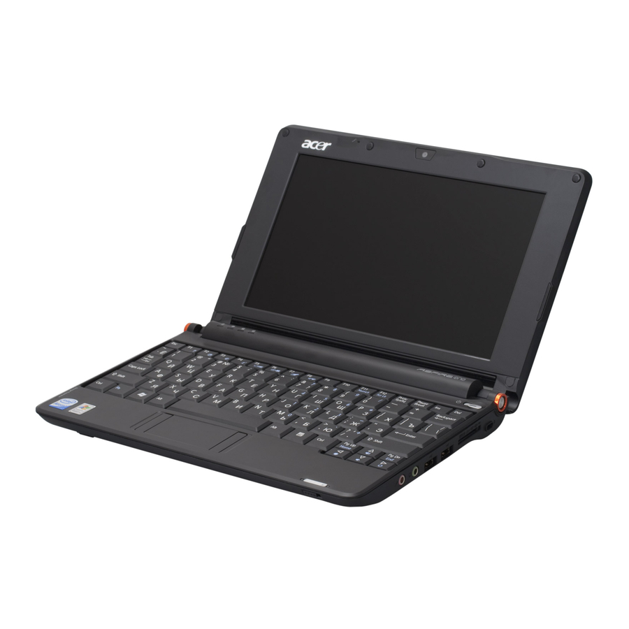
Your Acer Notebook tour After knowing your computer features, let us show you around your new computer. Front View Icon Item Microphone Internal microphone for sound recording. Acer Crystal Eye Web camera for video communication (only for Webcam certain models). -
Page 15: Closed Front View
Closed Front View Icon Left View Icon Chapter 1 Item Wireless Enables/disables the wireless function. communication switch Item DC-in jack Connects to an AC adapter External display Connects to a display device (VGA) port (e.g. external monitor, LCD projector). Ventilation slots Enable the computer to stay cool, even after and cooling fan prolonged use. -
Page 16: Right View
Right View Icon Rear View Icon Item Microphone-in jack Accepts input from external microphones. Headphones/ Connects to line-out audio devices speaker/line-out (e.g. speakers, headphones). jack USB 2.0 ports Connect to USB 2.0 devices (e.g. USB mouse). Multi-in-1 card Accepts Secure Digital (SD), MultiMediaCard reader (MMC), Memory Stick (MS), Memory Stick PRO (MS PRO), xD-Picture Card (xD). -
Page 17: Bottom View
Bottom View Icon Indicators The computer has several easy-to-read status indicators. The front panel indicators are visible even when the computer cover is closed. Icon Battery Num Lock Caps Lock NOTE: 1. Charging: The battery light shows amber when the battery is charging. 2. Fully charged: The light shows green when in AC mode. -
Page 18: Touchpad Basics
TouchPad Basics The following items show you how to use the TouchPad: Move your finger across the TouchPad (2) to move the cursor. • Press the left (1) and right (3) buttons located beneath the TouchPad to perform selection and •... -
Page 19: Using The Keyboard
Using the Keyboard Your Aspire one has a close-to-full-sized keyboard and an embedded numeric keypad, separate cursor, lock, function and special keys. Lock Keys and embedded numeric keypad The keyboard has three lock keys which you can toggle on and off. Lock key Caps Lock When Caps Lock is on, all alphabetic characters typed are in uppercase. -
Page 20: Hot Keys
Hot Keys The computer employs hotkeys or key combinations to access most of the computer's controls like screen brightness and volume output. To activate hotkeys, press and hold thekey before pressing the other key in the hotkey combination. Hotkey Icon ... -
Page 21: Special Key
Special Key You can locate the Euro symbol and the US dollar sign at the upper-center and/or bottom-right of your keyboard. The Euro symbol Open a text editor or word processor. Holdand then press the <5> key at the upper-center of the keyboard. NOTE: Some fonts and software do not support the Euro symbol. -
Page 22: Hardware Specifications And Configurations
Hardware Specifications and Configurations Processor Item CPU type CPU package Features System Controller Item Processor Support System Memory Support Internal Graphics Specification Diamondville Atrom series standard voltage 533FSB processors Diamondville 437-balls Micro-FCBGA8 package 22x22mm New single-core processor for mobile devices with enhanced •... - Page 23 Item Package System Clock Item System clock chip Package Clock Synthesizer Power Features Crystal and Oscillator Item Features System Memory Item Memory controller Memory size DIMM socket number Supports memory size per socket Supports maximum memory size Supports DIMM type Supports DIMM Speed System Storage Item...
- Page 24 Hard Disk Drive Interface Item Vendor & Segate ST9120817AS Model Name Capacity (MB) Bytes per sector Data heads Drive Format Disks Spindle 5400 speed (RPM) Performance Specifications Buffer 8 MB size Interface SATA Internal transfer rate (Mbits/ sec, max) I/O data transfer rate (Mbytes/...
- Page 25 Item Supply Current LCD 8.9” Item Vendor/model name Screen Diagonal (mm) Active Area (mm) Display resolution (pixels) Pixel Pitch (mm) Pixel Arrangement Display Mode Typical White Luminance (cd/m also called Brightness Luminance Uniformity Contrast Ratio Response Time (Optical Rise Time/Fall Time) msec Nominal Input Voltage VDD Typical Power Consumption (watt) Weight (without inverter)
- Page 26 • File deployment support • LDCM support • Specification New Acer flat keyboard Plug USB keyboard to the USB port directly: Yes Specification 2 mini card slot (1 for 3G and 1 for WLAN or WLAN/ • WiMax) Embedded 3G module and built-in 1 antenna (combo- •...
- Page 27 Camera Item Maximum Module Form Factor Sensor Type and Resolution Focusing Type Focusing Range Format of Image Output Data Frame Rate Operation Voltage System Interfacing Board Connector Type PCB layer Power consumption Weight 3G Card Item Type Features Wireless LAN Item Type Features...
- Page 28 Chapter 1...
-
Page 29: System Utilities
System Utilities BIOS Setup Utility The BIOS Setup Utility is a hardware configuration program built into your computer’s BIOS (Basic Input/ Output System). Your computer is already properly configured and optimized, and you do not need to run this utility. However, if you encounter configuration problems, you may need to run Setup. -
Page 30: Information
Distributed Computing Environment (DCE). InsydeH20 Setup Utility Boot Exit Genuine Intel (R) CPU N270 1.60GHz INTEL Castle Point 00008030320000000000 v0.2103 Intel V1585 ZG008160067 Acer 405FE2E9A4E1D4118251001E684CE894 F5/F6 Change Values Enter Select SubMenu Description Rev. 3.5 Setup Default Save and Exit Chapter 2... -
Page 31: Main
Main The Main screen allows the user to set the system time and date as well as enable and disable boot option and recovery. Information Main Security System Time System Date Total Memory Video Memory Quick Boot Network Boot F12 Boot Menu D2D Recovery ↑↓... -
Page 32: Security
Security The Security screen contains parameters that help safeguard and protect your computer from unauthorized use. Information Main Security Supervisor Password Is: User Password Is: Set Supervisor Password Set User Password Power on password ↑↓ Help Select Item ←→ Exit Select Menu The table below describes the parameters in this screen. - Page 33 Setting a Password Follow these steps as you set the user or the supervisor password: Use the ↑ and ↓ keys to highlight the Set Supervisor Password parameter and press the Enter key. The Set Supervisor Password box appears: Type a password in the “Enter New Password” field. The password length can not exceeds 8 alphanumeric characters (A-Z, a-z, 0-9, not case sensitive).
- Page 34 Changing a Password Use the ↑ and ↓ keys to highlight the Set Supervisor Password parameter and press the Enter key. The Set Password box appears. Type the current password in the Enter Current Password field and press Enter. Type a password in the Enter New Password field. Retype the password in the Confirm New Password field.
-
Page 35: Boot
Boot This menu allows the user to decide the order of boot devices to load the operating system. Bootable devices includes the USB diskette drives, the onboard hard disk drive and the DVD drive in the module bay. Information Main Security Boot priority order: 1. -
Page 36: Exit
Exit The Exit screen allows you to save or discard any changes you made and quit the BIOS Utility. Information Main Security Exit Saving Changes Exit Discarding Changes Load Setup Defaults Discard Changes Save Changes ↑↓ Help Select Item ←→ Exit Select Menu The table below describes the parameters in this screen. -
Page 37: Bios Flash Utility
BIOS Flash Utility The BIOS flash memory update is required for the following conditions: New versions of system programs • New features or options • Restore a BIOS when it becomes corrupted. • Use the Phlash utility to update the system BIOS flash ROM. NOTE: Create a Crisis Recovery Media (such as USB HDD) before you use the Phlash utility. - Page 38 In flash BIOS, the message Please do not remove AC Power Source displays. NOTE: If the AC power is not connected, the following message displays. Plug in the AC power to continue. Flash is complete when the following message displays. Shutdown or reboot base on iflash.bat command.
-
Page 39: Remove Hdd/Bios Utility
Remove HDD/BIOS Utility This section provide you with removing HDD/BIOS method: Remove HDD Password: If you key in wrong HDD password three times, Hdd password error code displays. See the image • below. To reset the HDD password, run HDD_PW.EXE as follows: Key in hdd_pw 15494 0 Press 2. - Page 40 Remove BIOS Password: If you key in the wrong Supervisor Password three times, System Disabled displays on the screen. See the image below. To reset the BIOS password, run BIOS_PW.EXE as follows: Key in bios_pw 14452 0 Select one string from the list. Chapter 2...
- Page 41 Reboot the system and key in the selected string (qjjg9vy, 07yqmjd etc.) for the BIOS user password. Chapter 2...
- Page 42 Chapter 2...
-
Page 43: Machine Disassembly And Replacement
Machine Disassembly and Replacement This chapter contains step-by-step procedures on how to disassemble the notebook computer for maintenance and troubleshooting. Disassembly Requirements To disassemble the computer, you need the following tools: Wrist grounding strap and conductive mat for preventing electrostatic discharge •... -
Page 44: General Information
General Information Pre-disassembly Instructions Before proceeding with the disassembly procedure, make sure that you do the following: 1. Turn off the power to the system and all peripherals. 2. Unplug the AC adapter and all power and signal cables from the system. 3. -
Page 45: External Module Disassembly Process
External Module Disassembly Process External Modules Disassembly Flowchart The flowchart below gives you a graphic representation on the entire disassembly sequence and instructs you on the components that need to be removed during servicing. Disassembly is divided into two tiers. Tier 1 comprises of FRU parts that do not require complete disassembly of the computer. -
Page 46: Removing The Battery Pack
Removing the Battery Pack 1. Turn computer over. 2. Slide the battery lock/unlock latch to the unlock position. 3. Slide and hold the battery release latch to the release position (1), then slide out the battery pack from the main unit (2). -
Page 47: Removing The 3G Cover
Removing the 3G Cover 1. Remove the Battery Pack. See “Removing the Battery Pack” on page 36. 2. Loosen the ten captive screws from the Memory, HDD1, and HDD2 Covers. 3. Remove the two captive screws. 4. Lift the 3G cover up to remove. Chapter 3... -
Page 48: Removing The Keyboard
Removing the Keyboard 1. Turn the computer rightside up and unlock the three (3) securing latches. 2. Grasp the keyboard and lift up to remove. 3. Lift the keyboard over and disconnect the keyboard FFC. 4. Remove the keyboard and place it on a clean surface. Chapter 3... -
Page 49: Removing The Upper And Lower Covers
Removing the Upper and Lower Covers 1. Remove the Battery Pack. See “Removing the Battery Pack” on page 36. 2. Turn the computer upside down. Remove the three securing screws under the battery pack. 3. Remove the two rubber foot pads and the eight securing screws. Step Upper Cover M2*3 (NL) - Page 50 5. Remove the five (5) securing screws. Step Size Quantity Screw Type Upper Cover M2*5 (NL) 6. Grasp the bottom of the upper cover and pry apart. 7. Lift the upper cover to remove completely. Chapter 3...
-
Page 51: Lcd Module Disassembly Process
LCD Module Disassembly Process LCD Module Disassembly Flowchart Screw List Step Screw LCD Bezel M2*5 (NL) LCD Module M2*5 (NL) LCD Panel M2*4 (NL) LCD Brackets M2*3 (NL) Chapter 3 Quantity Color Black Black Black Black Part No. 86.TG607.004 86.TG607.004 86.W0107.003 86.TG607.004... -
Page 52: Removing The Lcd Module
Removing the LCD Module 1. Remove the Upper Cover. See “Removing the Upper and Lower Covers” on page 39. 2. Disconnect the LCD cable from its connector 3. Disconnect and remove the antenna cables from the housing well. NOTE: Main cable is black. The Auxiliary cable is white. Chapter 3... - Page 53 4. Remove the four securing screws from the hinges. Step Size Quantity Screw Type LCD Module M2*5 (NL) 5. Tilt the LCD module so it sits at a 90 degree angle. IMPORTANT:Ensure all cables are clear of the lower cover before removing the LCD module. 6.
-
Page 54: Removing The Lcd Bezel
Removing the LCD Bezel 1. Remove the LCD Module. See “Removing the LCD Module” on page 42. 2. Remove the four round and the two semi-rectangular screw caps. 3. Remove the six (6) securing screws. Step LCD Bezel M2*5 (NL) 4. -
Page 55: Removing The Camera Board
Removing the Camera Board 1. Remove the LCD Bezel. See “Removing the LCD Bezel” on page 44. 2. Disconnect the Camera Module cable from its connector as shown. 3. Remove the camera board from the LCD cover. Chapter 3... -
Page 56: Removing The Mic Board
Removing the MIC Board 1. Remove the LCD Bezel. See “Removing the LCD Bezel” on page 44. 2. Disconnect the MIC cable from its connector as shown. 3. Remove the MIC board from the LCD cover. Chapter 3... -
Page 57: Removing The Lcd Panel
Removing the LCD Panel 1. Remove the LCD Bezel. See “Removing the LCD Bezel” on page 44. 2. Disconnect the MIC cable. See “Removing the MIC Board” on page 46. 3. Remove the five (5) securing screws from the LCD Module. Step LCD Panel M2*4 (NL) -
Page 58: Removing The Lcd Brackets And Fpc Cable
6. Hold the LCD Panel from the sides and lift to remove. Place it on a clean surface. Removing the LCD Brackets and FPC Cable 1. Remove the LCD Panel. See “Removing the LCD Panel” on page 47. 2. Turn the LCD panel over on a clean surface. Remove the adhesive strips securing the LCD cable. 3. - Page 59 4. Remove the four securing screws (two each side) from the LCD Panel brackets. Step Size Quantity Screw Type LCD Brackets M2*3 NL NOTE: The brackets are paired diagonally and marked as shown below. Chapter 3...
-
Page 60: Main Unit Disassembly Process
Main Unit Disassembly Process Main Unit Disassembly Flowchart Screw List Step WLAN M2*3 (NL) USB/LED/Power M2*3 (NL) Board (HDD SKU) USB/LED/Power M2*3 (NL) Board (SSD SKU) SSD Module M2*3 Mainboard M2*3 Speaker Module M2*3 HDD Module M2.5*4 HDD Carrier M3*3.5 Thermal Module M2*3 Screw... -
Page 61: Removing The Wlan Module
Removing the WLAN Module 1. See “Removing the Battery Pack” on page 36. 2. Remove the securing screw as shown. Step WLAN Module M2*3 (NL) NOTE: The antenna cables were removed during the LCD module disassembly. See “Removing the LCD Module”... -
Page 62: Removing The Usb/Led/Power/Card Reader Board
Removing the USB/LED/Power/Card Reader Board 1. Remove the upper cover. See “Removing the Upper and Lower Covers” on page 39. 2. Remove the three (3) securing screws as shown. Step HDD SKU: M2*3 (NL) USB/LED/Power board SDD SKU: M2*3 (NL) USB/LED/Power board 3. -
Page 63: Removing The Ssd Module
4. Disconnect the cable and remove the board. Removing the SSD Module IMPORTANT:The SSD module is only available on the Aspire one SSD SKU. 1. Remove the mainboard. See “Removing the Mainboard” on page 55. 2. Disconnect the FFC from its connector. 3. - Page 64 4. Remove the two securing screws. Step Size Quantity Screw Type SSD Module M2*3 (NL) 5. Remove the SSD module. Chapter 3...
-
Page 65: Removing The Mainboard
Removing the Mainboard 1. Remove the Upper Cover. See “Removing the Upper and Lower Covers” on page 39. 2. Remove the WLAN module. See “Removing the WLAN Module” on page 51. 3. Remove the USB/LED/Power/Card Reader Board. See “Removing the USB/LED/Power/Card Reader Board” on page 52. -
Page 66: Removing The Speaker Module
6. Grip the mainboard and remove. NOTE: The SSD image may differ from the following illustration. Removing the Speaker Module 1. Remove the Upper Cover. See “Removing the Upper and Lower Covers” on page 39. 2. Peel back the two adhesive strips. Chapter 3... - Page 67 3. Remove the four (4) securing screws (2 on each side). Step Size Quantity Screw Type Speaker Module M2*3 (NL) 4. Remove the Speaker Module from the upper cover. Chapter 3...
-
Page 68: Removing The Hard Disk Drive Module
Removing the Hard Disk Drive Module IMPORTANT:The HDD is only available on the Aspire one HDD SKU. 1. Remove the mainboard. See “Removing the Mainboard” on page 55. 2. Remove the two securing screws to release the carrier. Step HDD Module M2.5*4 (NL) 3. - Page 69 4. Remove the four screws (two each side) securing the HDD to the carrier. Step Size Quantity Screw Type HDD Carrier M3*3.5 (NL) 5. Turn the HDD on its side and pull the carrier away. Chapter 3...
-
Page 70: Removing The Dimm Module
Removing the DIMM Module IMPORTANT:The Aspire one SSD SKU does not come standard with DIMM modules. The modules are optional components for this SKU. 1. Remove the mainboard. See “Removing the Mainboard” on page 55. 2. Push out the release latches on both sides of the DIMM socket to release the DIMM module. 3. -
Page 71: Removing The Thermal Module
Removing the Thermal Module 1. Remove the Mainboard. See “Removing the Mainboard” on page 55. 2. Turn the Mainboard CPU side up, and place it on a clean surface. 3. Grip the cable connector and disconnect the Fan cable from the mainboard. IMPORTANT:Do not grip the cable itself to prevent stripping. - Page 72 5. Remove the thermal module. Chapter 3...
-
Page 73: Lcd Module Reassembly Procedure
LCD Module Reassembly Procedure Replacing the LCD Brackets and FPC Cable 1. Replace the four LCD brackets as shown. IMPORTANT:The indicator pairs on the brackets must be located diagonally opposite each other. 2. Turn the LCD panel over and connect the FPC cable to the panel. 3. -
Page 74: Replacing The Lcd Panel
Replacing the LCD Panel IMPORTANT:Before installing, take care of the following items: All cabling must be tucked tightly and close to the panel • Check that the cables are tucked under the hinge brackets and run on the outside of the hinges •... -
Page 75: Replacing The Mic Board
Replacing the Mic Board 1. Replace the Mic board in to the case. Replacing the Camera Board 1. Replace the camera board in to the case. Chapter 3 2. Connect the MIC cable as shown. 2. Connect the camera cable as shown. -
Page 76: Replacing The Lcd Bezel
Replacing the LCD Bezel 1. Starting from the bottom, locate the bezel correctly and press down the edges until there are no gaps between the bezel and the LCD Module. 2. Replace the six screws and the rubber screw caps provided. Chapter 3... -
Page 77: Main Module Reassembly Procedure
Main Module Reassembly Procedure Replacing the Thermal Module 1. Replace the Fan module on the Mainboard. 3. Connect the Fan cable to the Mainboard. Replacing the DIMM Module IMPORTANT:The Aspire one SSD SKU does not come standard with DIMM modules. The modules are optional components. -
Page 78: Replacing The Hard Disk Drive Module
Replacing the Hard Disk Drive Module IMPORTANT:The HDD is only available on the Aspire one HDD computer SKU. 1. Place the HDD in the HDD carrier. 3. Hold the carrier and slide the HDD toward the mainboard until the interface connects. Replacing the Speaker Module 1. - Page 79 3. Replace the two adhesive strips. Chapter 3...
-
Page 80: Replacing The Mainboard
Replacing the Mainboard IMPORTANT:Before replacing the motherboard, take care of the following items: Check that LED isn’t broken (top of mainboard) • Check that the mylar next to the CPU module isn’t damaged (bottom of mainboard) • Check the thermal power supply cable is connected properly •... -
Page 81: Replacing The Sdd Module
Replacing the SDD Module IMPORTANT:The SSD module is only available on the Aspire one SSD computer SKU. 1. Place the SDD in the lower case. 3. Connect the FFC cable to the module and close the cable latch. Chapter 3 2. -
Page 82: Replacing The Usb/Led/Power/Card Reader Board
Replacing the USB/LED/Power/Card Reader Board IMPORTANT:Before installing the USB board, take care of the following items: Check that LED isn`t broken • SLIDER work smoothly • 1. Connect the cable to the board. 3. Replace the three or four screws (depending on SKU) to secure the module. 4. -
Page 83: Replacing The Wlan Board
Replacing the WLAN Board 1. Insert the WLAN board in to the socket. Replacing the LCM Module 1. Place the LCM module on to the lower cover at a 90 degree angle. IMPORTANT:Ensure all cables are clear of the hinges before replacing the LCM module. 2. - Page 84 3. Replace the antenna cables in the housing well, as shown. 4. Replace the two antenna cables. NOTE: The following is the correct cable-color to connector designation: Black to MAIN (left) and White to AUX (right). 5. Connect the LCD cable to the mainboard. Chapter 3...
-
Page 85: Replacing The Upper Cover
Replacing the Upper Cover IMPORTANT:While replacing the upper cover, take note of the following items: Check that the mainboard is tucked underneath the housing wells in the lower cover • Check that the speaker cable is attached • Check that the antenna cables are tucked inside the housing well and do not interfere with the card reader •... -
Page 86: Replacing The Keyboard
5. Turn the computer upside down and replace the eight securing screws on the bottom panel to attach the upper and lower covers. 6. Replace the two rubber foot pads. Replacing the Keyboard 1. Replace keyboard cable to the mainboard, and secure the locking latch. -
Page 87: Replacing The 3G Cover
Replacing the 3G cover 1. Replace the 3G cover. 2. Secure the two captive screws. Replacing the Battery 1. Slide and hold the battery release latch (1), insert 2. Slide the battery lock/unlock latch to the lock battery in to the main unit (2). position. - Page 88 Chapter 3...
-
Page 89: Troubleshooting
Common Problems Use the following procedure as a guide for computer problems. NOTE: The diagnostic tests are intended to test only Acer products. Non-Acer products, prototype cards, or modified options can give false errors and invalid system responses. Obtain the failing symptoms in as much detail as possible. -
Page 90: Power On Issue
Power On Issue If the system doesn’t power on, perform the following actions one at a time to correct the problem. Do not replace a non-defective FRUs: Computer Shutsdown Intermittently If the system powers off at intervals, perform the following actions one at a time to correct the problem. Check the power cable is properly connected to the computer and the electrical outlet. -
Page 91: No Display Issue
No Display Issue If the Display doesn’t work, perform the following actions one at a time to correct the problem. Do not replace a non-defective FRUs: Chapter 4... - Page 92 No POST or Video If the POST or video doesn’t display, perform the following actions one at a time to correct the problem. Make sure that the internal display is selected. On this notebook model, switching between the internal display and the external display is done by pressing Fn+F5. Reference Product pages for specific model procedures.
-
Page 93: Random Loss Of Bios Settings
Abnormal Video Display If video displays abnormally, perform the following actions one at a time to correct the problem. Reboot the computer. If permanent vertical/horizontal lines or dark spots display in the same location, the LCD is faulty and should be replaced. See “Disassembly Process” on page 34. If extensive pixel damage is present (different colored spots in the same locations on the screen), the LCD is faulty and should be replaced. -
Page 94: Lcd Failure
LCD Failure If the LCD fails, perform the following actions one at a time to correct the problem. Do not replace a non- defective FRUs: Built-In Keyboard Failure If the built-in Keyboard fails, perform the following actions one at a time to correct the problem. Do not replace a non-defective FRUs: Chapter 4... -
Page 95: Touchpad Failure
TouchPad Failure If the TouchPad doesn’t work, perform the following actions one at a time to correct the problem. Do not replace a non-defective FRUs: Internal Speaker Failure If the internal Speakers fail, perform the following actions one at a time to correct the problem. Do not replace a non-defective FRUs: Sound Problems If sound problems are experienced, perform the following actions one at a time to correct the problem. - Page 96 The device is properly installed. • There are no red Xs or yellow exclamation marks. • There are no device conflicts. • No hardware is listed under Other Devices. • Roll back the audio driver to the previous version, if updated recently. Remove and reinstall the audio driver.
-
Page 97: Internal Microphone Failure
Internal Microphone Failure If the internal Microphone fails, perform the following actions one at a time to correct the problem. Do not replace a non-defective FRUs: Microphone Problems If internal or external Microphones do no operate correctly, perform the following actions one at a time to correct the problem. -
Page 98: Hdd Not Operating Correctly
HDD Not Operating Correctly If the HDD does not operate correctly, perform the following actions one at a time to correct the problem. Disconnect all external devices. Run a complete virus scan using up-to-date software to ensure the computer is virus free. Run the Windows Vista Startup Repair Utility: insert the Windows Vista Operating System DVD in the ODD and restart the computer. -
Page 99: Usb Failure (Rightside)
USB Failure (Rightside) If the rightside USB port fails, perform the following actions one at a time to correct the problem. Do not replace a non-defective FRUs: Power Button Failure If the Power Button fails, perform the following actions one at a time to correct the problem. Do not replace a non-defective FRUs: Chapter 4... -
Page 100: External Mouse Failure
External Mouse Failure If an external Mouse fails, perform the following actions one at a time to correct the problem. Try an alternative mouse. If the mouse uses a wireless connection, insert new batteries and confirm there is a good connection. See the mouse user manual. -
Page 101: Intermittent Problems
Issue” on page 80): Power-off the computer. Visually check them for damage. If any problems are found, replace the FRU. Remove or disconnect all of the following devices: Non-Acer devices • Printer, mouse, and other external devices • Battery pack •... -
Page 102: Frequently Asked Questions (Faq)
If I want to expand the memory and storage capacity of my Acer Aspire one, how can I do so? Acer Aspire one allows the user to expand the memory using the expansion slot on the base of the machine. Please refer to the system specifications to obtain related information on suitable memory models. The internal storage device of Acer Aspire one does not support expansion. - Page 103 How does Acer Aspire one perform System Recovery? Each Acer Aspire one is bundled with a system recovery CD during shipping. At any time, users can restore the machine to the initial factory settings. The user must configure the BIOS to boot from USB CD-ROM (See “Boot”...
- Page 104 How can I remove redundant input methods? Only the Traditional and Simplified Chinese versions of Linpus Linux Lite support this function. How can I add more input methods? Only the Traditional and Simplified Chinese versions of Linpus Linux Lite support this function. How can I select or switch input modes from my keyboard? Only the Traditional and Simplified Chinese versions of Linpus Linux Lite support this function.
- Page 105 Is there a shortcut back to the Home Page? At the lower left corner of the Desktop Taskbar, there is a Home icon. Click the icon to minimize all the open windows and display the Home page. How can I read the date from USB drive and CD/DVD-ROM? Plug in the USB drive or insert the CD in CD/DVD-Rom, Linpus Linux Lite will automatically detect and mount.
- Page 106 Click on the network manager icon and select the desired wireless access point. The network manager automatically detects the security protocol and then requests the password. How do I setup a Network Printer? Using a Windows network as an example: Select Setting Printer and click New Printer on the Toolbar.
- Page 107 Why doesn’t my Network Printer work? When troubleshooting installation of the network printer, confirm whether the following conditions are true: Does the network device activate or not? • Does your system connect successfully to local area network (LAN)? • Does your system install Samba and activate the service? •...
- Page 108 How can I adjust the Date, Time, or Timezone? Select Settings Date/Time to display the setting menu. Make any desired adjustment to time, date, or time zone. Where is the system performance monitor? Press Ctrl+Alt+Del to display the System Monitor. Click Resources to view system status. Chapter 4...
- Page 109 Where can I view peripheral devices available to my system? Press Ctrl+Alt+Del to display the System Monitor. Click File Systems to view available peripheral devices. Where can I view processes running on my system? Press Ctrl+Alt+Del to display the System Monitor. Click Processes to view programs and application status. How can I set the screensaver? Screensavers are not customizable with this version.
- Page 110 How can I reset the logon password? Select Settings User & Password. Click Change Password and follow the onscreen prompts to change your password. After using OpenOffice what happens to my old MS Office format files? Do I need to recreate the files? Is there a conversion utility? OpenOffice can not only read MS Office format files, but also save files as MS Office 95/97/2000/XP format so there is no need to recreate the old files.
- Page 111 Why are some Flash webpages unable to display normally in Firefox? Ensure you have the latest Flash Player Installers from Linux in Adobe Lab (http://labs.adobe.com/). How do I browse PDF files? The system ships with Adobe Reader 8 for Linux, which can open pdfs directly and operates similarly to the Windows version.
-
Page 112: Post Code Reference Tables
POST Code Reference Tables These tables describe the POST codes and components of the POST process. Sec: NO_EVICTION_MODE_DEBUG EQU 1 (CommonPlatform\sec\Ia32\SecCore.inc) Code 0xC2 MTRR setup 0xC3 Enable cache 0xC4 Establish cache tags 0xC5 Enter NEM, Place the BSP in No Fill mode, set CR0.CD = 1, CR0.NW = 0. 0xCF Cache Init Finished Memory:... -
Page 113: Bds & Specific Action
Code 0x27 Enable DRAM Channel I/O Buffers 0x28 Enable all clocks on populated rows 0x29 Perform JEDEC memory initialization for all memory rows 0x30 Perform steps required after memory init 0x31 Program DRAM throttling and throttling event registers 0x32 Setup DRAM control register for normal operation and enable 0x33 Enable RCOMP 0x34... - Page 114 Code 0xF8 Report that ExitBootServices() has been called 0xF9 Runtime driver set virtual address map Component Chapter 4...
-
Page 115: Each Peim Entry Point Used In 80_Port
Each PEIM entry point used in 80_PORT Code 0x00 0x01 PEI_EVENT_LOG 0x02 PEI_OEM_SERVICE 0x03 PEI_SIO_INIT 0x04 PEI_MONO_STATUS_CODE 0x05 PEI_CPU_IO_PCI_CFG 0x06 PEI_CPU_IO 0x07 PEI_PCI_CFG 0x08 PEI_CPU_PEIM 0x09 PEI_PLATFORM_STAGE1 0x0A PEI_VARIABLE 0x0B PEI_SB_INIT 0x0C PEI_CAPSULE 0x0D PEI_PLATFORM_STAGE2 0x0E PEI_SB_SMBUS_ARP_DISABLED 0x0F PEI_HOST_TO_SYSTEM 0x10 PEI_MEMORY_INIT 0x11 PEI_S3_RESUME... - Page 116 Code 0x3B MONOTONIC_COUNTER 0x3C WATCH_DOG_TIMER 0x3D SECURITY_STUB 0x3E DXE_CPU_IO 0x3F CF9_RESET 0x40 PC_RTC 0x41 STATUS_CODE 0x42 VARIABLE 0x43 EMU_VARIABLE 0x44 DXE_CHIPSET_INIT 0x45 DXE_ALERT_FORMAT 0x46 PCI_HOST_BRIDGE 0x47 PCI_EXPRESS 0x48 DXE_SB_INIT 0x49 IDE_CONTROLLER 0x4A SATA_CONTROLLER 0x4B SB_SM_BUS 0x4C ISA_ACPI_DRIVER 0x4D ISA_BUS 0x4E ISA_SERIAL 0x4F IDE_BUS...
- Page 117 Code 0x66 BIOS_KEYBOARD 0x67 BIOS_VEDIO 0x68 MONITER_KEY 0x69 LEGACY_BIOS 0x6A LEGACY_BIOS_PLATFORM 0x6B PCI_PLATFORM 0x6C ISA_FLOOPY 0x6D PS2_MOUSE 0x6E USB_BOT 0x6F USB_CBI0 0x70 USB_CBI1 0x71 USB_KB 0x72 USB_MASS_STORAGE 0x73 BUS_PCI_UHCI 0x74 USB_MOUSE 0x75 USB_BUS 0x76 SETUP_UTILITY 0x77 FW_BLOCK_SERVICE 0x78 USB_LEGACY_PLATFORM 0x79 GRAPHICS_CONSOLE 0x7A TERMINAL...
-
Page 118: Each Smmdriver Entry Point Used In 80_Port
Code 0x91 PXE_BC 0x92 PXE_DHCP4 0x93 0x94~0x9F RESERVED 0xA0 DXE_H2O_DEBUG_IO 0xA1 DXE_H2O_DEBUG_IO 0xA2 DXE_TPM_TCG 0xA3 DXE_TPM_PHYSICAL_PRESENCE 0xA4 DXE_OEM_SERVICE 0xA5 DXE_EVENT_LOG 0xA6 DXE_ SECURITY_HDD_PASSWORD_SERVICE 0xA7 DXE_LAN_ASF_INIT 0xA8 DXE_BUS_PCI_SERIAL 0xA9 DXE_LAN_IDER_CONTROLLER 0xAA DXE_LAN_AMT 0xAB DXE_ SECURITY_SYSTEM_PASSWORD_SERVICE 0xAC DXE_ SECURITY_ PASSWORD_CONSOLE 0xAD DXE_ DATA_HUB_RECORD_POLICY 0xAE DXE_TPM_DRIVER 0xAF... - Page 119 Code 0xD2 SMM_PNP 0xD3 SMM_USB_LEGACY 0xD4 SMM_INT13_HDD 0xD5 SMM_INIT_PPM 0xD6 SMM_OHCI1394 0xD7 SMM_ SECURITY_HDD_PASSWORD_SERVICE 0xD8 SMM_OEM_SERVICE 0xD9 SMM_PPM 0xDA SMM_DIGITAL_THERMAL_SENSOR Chapter 4 Component...
- Page 120 Chapter 4...
-
Page 121: Jumper And Connector Locations
Jumper and Connector Locations Top View Description LCD Connector Powerboard Connector Keyboard Connector DDR3 Connector Chapter 5 Description MDC Connector ExpressCard Board Connector Bluetooth Connector PCMCIA Connector Chapter 5... -
Page 122: Bottom View
Bottom View Description CPU Socket DDR2 Connector Battery Connector ODD Connector HDD Connector Card Reader Connector HDD Connector MXM Connector Audio Connector Audio Connector SPDIF Connector USB Connector HDMI Connector CRT Connector Docking Connector RJ 45 DC Jack Description Chapter 5... -
Page 123: Clearing Password Check And Bios Recovery
Clearing Password Check and BIOS Recovery This section provide you the standard operating procedures of clearing password and BIOS recovery for Aspire one. Aspire one provide one Hardware Open Gap on main board for clearing password check, and one Hotkey for enabling BIOS Recovery. Clearing Password Check Hardware Open Gap Description Item... -
Page 124: Bios Recovery By Crisis Disk
BIOS Recovery by Crisis Disk BIOS Recovery Boot Block: BIOS Recovery Boot Block is a special block of BIOS. It is used to boot up the system with minimum BIOS initialization. Users can enable this feature to restore the BIOS firmware to a successful one once the previous BIOS flashing process failed. -
Page 125: Fru (Field Replaceable Unit) List
Guide. For ACER AUTHORIZED SERVICE PROVIDERS, your Acer office may have a DIFFERENT part number code from those given in the FRU list of this printed Service Guide. You MUST use the local FRU list provided by your regional Acer office to order FRU parts for repair and service of customer machines. -
Page 126: Aspire One Exploded Diagram
Aspire one Exploded Diagram Item Description Mainboard Power Board Upper Case Lower Case Part Number Item MB.S0306.001 Left Hinge (SDD SKU) MB.S0506.001 (HDD SKU) 55.S0207.001 LCD Bezel 60.S0207.001 LCD Panel 60.S0607.001 60.S0307.001 60.S0707.001 60.S0207.002 Camera Module 60.S0407.001 60.S0607.002 60.S0807.001 60.S0307.002 60.S0507.001 60.S0707.002 60.S0907.001... - Page 127 Item Description 3G Cover Rubber Foot Card Reader Cable Thermal Module Screw Screw Screw Screw Screw LCD Case Chapter 6 Part Number Item 42.S0207.001 LCD Bracket 42.S0307.001 42.S0407.001 42.S0507.001 47.S0207.003 Mirror LCD Bracket 50.S0207.001 LCD Cable 60.S0207.005 Rubber Screw Cap Mylar Screw Cap See “Screw List”...
-
Page 128: Aspire One Fru List
Aspire one FRU List Category Adapter ADAPTER LITE-ON 30W 1.7X5.5X11 BLACK PA-1300-04AC LF Battery BATTERY SIMPLO UM-2008AW LI-ION 3S1P PANASONIC 3 CELL 2200MAH MAIN COMMON MACLES / WHITE BATTERY SIMPLO UM-2008A LI-ION 3S1P SAMSUNG 3 CELL 4400MAH MAIN COMMON MACLES BATTERY SIMPLO UM-2008A LI-ION 3S1P SAMSUNG 3 CELL 4800MAH MAIN COMMON MACLES Battery SIMPLO UM-2008AW Li-Ion 3S1P SAMSUNG 3 cell... - Page 129 Category Cables POWER CORD US 3PIN ROHS POWER CORD PRC 3P Y536B30001218008 POWER CORD(S.A) 1.8M 3BLACK FZ010008-006 ARGENTINE POWER CORD 3 PIN BLACK POWER CORD AU W/LABEL (3 PIN) POWER CORD(EU) 1.8M 3PBLACK FM010008-010 PWR CORD V943B30001218008 DANISH 3P PWR CORD(ISR)1.8M 3PBLK FZ0I0008-038 POWER CORD ITALIAN 3PIN POWER CORD JAPAN POWER CORD AF-S (INDIA)
- Page 130 Category LOWER CASE ASSY BLUE COLOR HDD W/SPEAKER FOR WLAN UPPER CASE ASSY BLUE COLOR W/TP FFC FOR 3G LOWER CASE ASSY BLUE COLOR W/SPEAKER FOR WLAN LOWER CASE ASSY BLUE COLOR HDD W/SPEAKER FOR WLAN 3G 3G COVER WHITE COLOR 3G COVER BLUE COLOR 3G COVER WHITE COLOR FOR HDD SKU 3G COVER BLUE COLOR FOR HDD SKU...
- Page 131 Category HDD BRACKET FLASH DISK SANDISK FLASH MODULE NAND 4GB SDUS5FJ- 004G LF FLASH DISK INTEL FLASH MODULE NAND 4GB SSDPAMM0004G1 LF MM#898543 Flash Disk INTEL Flash Module NAND 8GB SSDPAMM0008G1 LF MM#898544 Keyboard KEYBOARD 8KB-FV1 BLACK MACLES 84KS BLACK TRADITIONAL CHINESE KEYBOARD 8KB-FV1 BLACK MACLES 84KS BLACK GREEK KEYBOARD 8KB-FV1 BLACK MACLES 84KS BLACK...
- Page 132 Category KEYBOARD 8KB-FV1 BLACK MACLES 85KS BLACK PORTUGUESE KEYBOARD 8KB-FV1 BLACK MACLES 84KS BLACK US INTERNATIONAL HEBREW KEYBOARD 8KB-FV1 BLACK MACLES 85KS BLACK NORWEGIAN KEYBOARD 8KB-FV1 BLACK MACLES 84KS BLACK KOREAN KEYBOARD 8KB-FV2 WHITE MACLES 84KS WHITE TRADITIONAL CHINESE KEYBOARD 8KB-FV2 WHITE MACLES 84KS WHITE GREEK KEYBOARD 8KB-FV2 WHITE MACLES 84KS WHITE THAILAND KEYBOARD 8KB-FV2 WHITE MACLES 85KS WHITE SLO/CRO...
- Page 133 Category KEYBOARD 8KB-FV1L BLACK MACLES 84KS BLACK TRADITIONAL CHINESE (LINUX) KEYBOARD 8KB-FV1L BLACK MACLES 84KS BLACK GREEK (LINUX) KEYBOARD 8KB-FV1L BLACK MACLES 84KS BLACK THAILAND (LINUX) KEYBOARD 8KB-FV1L BLACK MACLES 85KS BLACK SLO/ CRO (LINUX) KEYBOARD 8KB-FV1L BLACK MACLES 85KS BLACK CZECH (LINUX) KEYBOARD 8KB-FV1L BLACK MACLES 85KS BLACK HUNGARIAN (LINUX)
- Page 134 Category KEYBOARD 8KB-FV1L BLACK MACLES 85KS BLACK PORTUGUESE (LINUX) KEYBOARD 8KB-FV1L BLACK MACLES 84KS BLACK US INTERNATIONAL HEBREW (LINUX) KEYBOARD 8KB-FV1L BLACK MACLES 85KS BLACK NORWEGIAN (LINUX) KEYBOARD 8KB-FV1L BLACK MACLES 84KS BLACK KOREAN (LINUX) KEYBOARD 8KB-FV2L WHITE MACLES 84KS WHITE TRADITIONAL CHINESE (LINUX) KEYBOARD 8KB-FV2L WHITE MACLES 84KS WHITE GREEK (LINUX)
- Page 135 Category KEYBOARD 8KB-FV2L WHITE MACLES 85KS WHITE SPANISH (LINUX) KEYBOARD 8KB-FV2L WHITE MACLES 84KS WHITE ARABIC/ ENGLISH (LINUX) KEYBOARD 8KB-FV2L WHITE MACLES 84KS WHITE US INTERNATIONAL (LINUX) KEYBOARD 8KB-FV2L WHITE MACLES 85KS WHITE SWISS/ G (LINUX) KEYBOARD 8KB-FV2L WHITE MACLES 85KS WHITE PORTUGUESE (LINUX) KEYBOARD 8KB-FV2L WHITE MACLES 84KS WHITE US INTERNATIONAL HEBREW (LINUX)
-
Page 136: Screw List
Category Miscellaneous LCD BEZEL RUBBER LCD BEZEL MYLAR RUBBER FOOT Screw List Item SCREW SCREW M2.5*4.0-I(NI)(NYLOK) SCREW SCREW M2.0*3.0-I(NI)(NYLOK) SCREW SCREW M2.0*3.0-I IRON SCREW SCREW 2.0*4.0 SCREW SCREW M2*5-I(BZN)(NYLOK) SCREW SCREW M2.0*5.0-I(NI) SCREW SCREW M3*0.5+3.5I Description Description 86.D01V7.001 86.TDY07.002 86.S0207.001 86.W0107.003 86.TG607.004 86.S0207.002... - Page 137 Chapter 6...
-
Page 138: Model Definition And Configuration
EMEA Greece AOA150-Ab EMEA Norway AOA150-Ab EMEA Italy AOA150-Ab EMEA Turkey Appendix A Acer Part No Description S2.S050B.001 AOA150-Bb AOXPHSTWW1 MC UMACb 2*512/ 80/6L/5R/CB_bg_0.3D_GE_EN11_C1 (TW) S2.S050A.001 AOA150-Ab AOLINXSWW1 UMACb 2*512/80/ 6L/5R/CB_bg_0.3D_GE_EN11_C1 (TW) LU.S050A.050 AOA150-Ab AOLINXSDE1 UMACb 2*512/80/3L/ 5R/CB_bg_0.3D_BAG_GE_IT31 LU.S050A.048 AOA150-Ab AOLINXSEU4 UMACb 2*512/80/3L/ 5R/CB_bg_0.3D_BAG_GE_EN81... - Page 139 EMEA Israel AOA150-Ab EMEA Denmark AOA150-Ab EMEA Norway AOA150-Ab EMEA South Africa Country Acer Part No LU.S050A.055 AOA150-Ab AOLINXSRU1 UMACb 2*512/80/ 3L/5R/CB_bg_0.3D_BAG_GE_RU21 LU.S050A.057 AOA150-Ab AOLINXSEU6 UMACb 2*512/80/3L/ 5R/CB_bg_0.3D_BAG_GE_EN21 LU.S050A.061 AOA150-Ab AOLINXSSI1 UMACb 2*512/80/3L/ 5R/CB_bg_0.3D_BAG_GE_EN11 LU.S050A.073 AOA150-Ab AOLINXSCH1 UMACb 2*512/80/ 3L/5R/CB_bg_0.3D_BAG_GE_IT41 LU.S050A.072...
- Page 140 EMEA Norway AOA150-Bb EMEA Eastern Europe AOA150-Bb EMEA South Africa Appendix A Country Acer Part No LU.S050A.093 AOA150-Ab AOLINXSPT1 UMACb 1*512/80/3L/ 5R/CB_bg_0.3D_BAG_GE_PT21 LU.S050A.081 AOA150-Ab AOLINXSEU4 UMACb 1*512/80/3L/ 5R/CB_bg_0.3D_BAG_GE_EN81 LU.S050A.079 AOA150-Ab AOLINXSDE1 UMACb 1*512/80/3L/ 5R/CB_bg_0.3D_BAG_GE_IT31 LU.S050A.080 AOA150-Ab AOLINXSSE1 UMACb 1*512/80/3L/ 5R/CB_bg_0.3D_BAG_GE_EN81 LU.S050A.082...
- Page 141 Europe AOA150-Bb EMEA Czech AOA150-Bb EMEA Hungary AOA150-Bb EMEA Italy Country Acer Part No LU.S050B.078 AOA150-Bb AOXPHSTEU5 MC UMACb 2*512/ 80/3L/5R/CB_bg_0.3D_BAG_GE_PL12 LU.S050B.077 AOA150-Bb AOXPHSTSE1 MC UMACb 2*512/ 80/3L/5R/CB_bg_0.3D_BAG_GE_FI12 LU.S050B.081 AOA150-Bb AOXPHSTNL1 MC UMACb 2*512/ 80/3L/5R/CB_bg_0.3D_BAG_GE_NL12 LU.S050B.067 AOA150-Bb AOXPHSTME2 MC UMACb 1*512/ 80/3L/5R/CB_bg_0.3D_BAG_GE_EN12...
- Page 142 EMEA Russia AOA150-Ab EMEA Slovenia/ Croatia AOA150-Ab EMEA Turkey Appendix A Country Acer Part No LU.S050B.058 AOA150-Bb AOXPHSTPT1 MC UMACb 1*512/ 80/3L/5R/CB_bg_0.3D_BAG_GE_PT12 LU.S050B.064 AOA150-Bb AOXPHSTME2 MC UMACb 1*512/ 80/3L/5R/CB_bg_0.3D_BAG_GE_AR22 LU.S050B.065 AOA150-Bb AOXPHSTME3 MC UMACb 1*512/ 80/3L/5R/CB_bg_0.3D_BAG_GE_FR22 LU.S050B.066 AOA150-Bb AOXPHSTME9 MC UMACb 1*512/ 80/3L/5R/CB_bg_0.3D_BAG_GE_FR22...
- Page 143 Australia/ Zealand AOA150-Ab Philippines AOA150-Ab Vietnam AOA150-Ab Japan AOA150-Ab India AOA150-Ab Thailand Country Acer Part No LU.S050A.118 AOA150-Ab AOLINXSIT1 UMACb 2*512/80/3L/ 5R/CB_bg_0.3D_BAG_GE_IT31 LU.S050A.130 AOA150-Ab AOLINXSNO1 UMACb 2*512/80/ 3L/5R/CB_bg_0.3D_BAG_GE_DA11 LU.S050A.120 AOA150-Ab AOLINXSGR1 UMACb 2*512/80/ 3L/5R/CB_bg_0.3D_BAG_GE_EL41 LU.S050A.122 AOA150-Ab AOLINXSPT1 UMACb 2*512/80/3L/ 5R/CB_bg_0.3D_BAG_GE_PT21 LU.S050A.128...
- Page 144 Japan AOA150-Bb India AOA150-Bb Australia/ Zealand AOA150-Bb Philippines AOA150-Bb Singapore Appendix A Country Acer Part No LU.S050A.037 AOA150-Ab AOLINXSID1 UMACb 512+1G/120/ 6L/5R/CB_bg_0.3D_BAG_GE_EN11 LU.S050A.032 AOA150-Ab AOLINXSTH1 UMACb 1*512/120/ 6L/5R/CB_bg_0.3D_BAG_GE_TH21 LU.S050A.040 AOA150-Ab AOLINXSPH1 UMACb 512+1G/ 120/6L/5R/CB_bg_0.3D_BAG_GE_EN11 LU.S050A.039 AOA150-Ab AOLINXSJP1 UMACb 512+1G/120/ 6L/5R/CB_bg_0.3D_BAG_GE_JA11 LU.S050A.036...
- Page 145 ACLA- Spanish AOA150-Ab AOA150-Ab Canada AOA150-Ab ACLA- Spanish AOA150-Ab ACLA- Spanish Country Acer Part No LU.S050B.025 AOA150-Bb AOXPHSTMY1 MC UMACb 512+1G/120/6L/5R/ CB_bg_0.3D_BAG_GE_EN11 LU.S050B.016 AOA150-Bb AOXPHSTMY1 MC UMACb 2*512/ 120/6L/5R/CB_bg_0.3D_BAG_GE_EN11 LU.S050B.017 AOA150-Bb AOXPHSTTH1 MC UMACb 2*512/ 120/6L/5R/CB_bg_0.3D_BAG_GE_TH21 LU.S050B.032 AOA150-Bb AOXPHSTTH1 MC UMACb 1*512/ 120/6L/5R/CB_bg_N_BAG_GE_TH21 LU.S050B.031...
- Page 146 AOA150-Ab NLED8.9WSVGAG AOA150-Ab NLED8.9WSVGAG AOA150-Ab NLED8.9WSVGAG AOA150-Ab NLED8.9WSVGAG AOA150-Ab NLED8.9WSVGAG Appendix A Country Acer Part No LU.S050A.008 AOA150-Ab AOLINXSXC1 UMACb 2*512/120/ 6L/5R/CB_bg_0.3D_BAG_GE_XC21 LU.S050A.109 AOA150-Ab AOLINXSXC1 UMACb 2*512/120/ 3L/5R/CB_bg_0.3D_BAG_GE_XC21 LU.S050A.007 AOA150-Ab AOLINXSUS1 UMACb 2*512/120/ 6L/5R/CB_bg_0.3D_BAG_GE_EN31 LU.S050B.001 AOA150-Bb AOXPHSTUS1 MC UMACb 512+1G/120/6L/5R/ CB_bg_0.3D_BAG_GE_EN31...
- Page 147 Model AOA150-Ab NLED8.9WSVGAG AOA150-Ab NLED8.9WSVGAG AOA150-Ab NLED8.9WSVGAG AOA150-Ab NLED8.9WSVGAG AOA150-Ab NLED8.9WSVGAG AOA150-Ab NLED8.9WSVGAG AOA150-Ab NLED8.9WSVGAG AOA150-Ab NLED8.9WSVGAG AOA150-Ab NLED8.9WSVGAG AOA150-Ab NLED8.9WSVGAG AOA150-Ab NLED8.9WSVGAG AOA150-Ab NLED8.9WSVGAG AOA150-Ab NLED8.9WSVGAG AOA150-Ab NLED8.9WSVGAG AOA150-Ab NLED8.9WSVGAG AOA150-Ab NLED8.9WSVGAG AOA150-Bb NLED8.9WSVGAG AOA150-Ab NLED8.9WSVGAG AOA150-Bb NLED8.9WSVGAG AOA150-Ab NLED8.9WSVGAG AOA150-Bb NLED8.9WSVGAG...
- Page 148 Model AOA150-Ab NLED8.9WSVGAG AOA150-Ab NLED8.9WSVGAG AOA150-Ab NLED8.9WSVGAG AOA150-Ab NLED8.9WSVGAG AOA150-Ab NLED8.9WSVGAG AOA150-Ab NLED8.9WSVGAG AOA150-Ab NLED8.9WSVGAG AOA150-Bb NLED8.9WSVGAG AOA150-Bb NLED8.9WSVGAG AOA150-Bb NLED8.9WSVGAG AOA150-Bb NLED8.9WSVGAG AOA150-Bb NLED8.9WSVGAG AOA150-Bb NLED8.9WSVGAG AOA150-Bb NLED8.9WSVGAG AOA150-Bb NLED8.9WSVGAG AOA150-Bb NLED8.9WSVGAG AOA150-Bb NLED8.9WSVGAG AOA150-Bb NLED8.9WSVGAG AOA150-Bb NLED8.9WSVGAG AOA150-Bb NLED8.9WSVGAG AOA150-Bb NLED8.9WSVGAG...
- Page 149 Model AOA150-Bb NLED8.9WSVGAG AOA150-Bb NLED8.9WSVGAG AOA150-Bb NLED8.9WSVGAG AOA150-Bb NLED8.9WSVGAG AOA150-Bb NLED8.9WSVGAG AOA150-Bb NLED8.9WSVGAG AOA150-Bb NLED8.9WSVGAG AOA150-Bb NLED8.9WSVGAG AOA150-Bb NLED8.9WSVGAG AOA150-Bb NLED8.9WSVGAG AOA150-Bb NLED8.9WSVGAG AOA150-Bb NLED8.9WSVGAG AOA150-Bb NLED8.9WSVGAG AOA150-Bb NLED8.9WSVGAG AOA150-Bb NLED8.9WSVGAG AOA150-Bb NLED8.9WSVGAG AOA150-Bb NLED8.9WSVGAG AOA150-Bb NLED8.9WSVGAG AOA150-Ab NLED8.9WSVGAG AOA150-Ab NLED8.9WSVGAG AOA150-Ab NLED8.9WSVGAG...
- Page 150 Model AOA150-Ab NLED8.9WSVGAG AOA150-Bb NLED8.9WSVGAG AOA150-Bb NLED8.9WSVGAG AOA150-Bb NLED8.9WSVGAG AOA150-Bb NLED8.9WSVGAG AOA150-Ab NLED8.9WSVGAG AOA150-Ab NLED8.9WSVGAG AOA150-Ab NLED8.9WSVGAG AOA150-Ab NLED8.9WSVGAG AOA150-Ab NLED8.9WSVGAG AOA150-Ab NLED8.9WSVGAG AOA150-Ab NLED8.9WSVGAG AOA150-Ab NLED8.9WSVGAG AOA150-Ab NLED8.9WSVGAG AOA150-Ab NLED8.9WSVGAG AOA150-Ab NLED8.9WSVGAG AOA150-Ab NLED8.9WSVGAG AOA150-Ab NLED8.9WSVGAG AOA150-Ab NLED8.9WSVGAG AOA150-Ab NLED8.9WSVGAG AOA150-Ab NLED8.9WSVGAG...
- Page 151 Model AOA150-Bb NLED8.9WSVGAG AOA150-Bb NLED8.9WSVGAG AOA150-Bb NLED8.9WSVGAG AOA150-Bb NLED8.9WSVGAG AOA150-Bb NLED8.9WSVGAG AOA150-Bb NLED8.9WSVGAG AOA150-Ab NLED8.9WSVGAG AOA150-Bb NLED8.9WSVGAG AOA150-Bb NLED8.9WSVGAG AOA150-Ab NLED8.9WSVGAG AOA150-Ab NLED8.9WSVGAG AOA150-Bb NLED8.9WSVGAG AOA150-Bb NLED8.9WSVGAG AOA150-Ab NLED8.9WSVGAG AOA150-Ab NLED8.9WSVGAG AOA150-Ab NLED8.9WSVGAG AOA150-Ab NLED8.9WSVGAG AOA150-Ab NLED8.9WSVGAG AOA150-Ab NLED8.9WSVGAG AOA150-Ab NLED8.9WSVGAG AOA150-Ab NLED8.9WSVGAG...
-
Page 152: Aspire One White
EMEA Norway AOA150-Aw EMEA Italy AOA150-Aw EMEA Belgium AOA150-Aw EMEA Turkey Appendix A Acer Part No Description S2.S040B.001 AOA150-Bw AOXPHSTWW1 MC UMACw 2*512/ 80/6L/5R/CB_bg_0.3D_GE_EN11_C1 (TW) LU.S040A.051 AOA150-Aw AOLINXSEU4 UMACw 2*512/80/3L/ 5R/CB_bg_0.3D_BAG_GEw_EN81 LU.S040A.048 AOA150-Aw AOLINXSDE1 UMACw 2*512/80/3L/ 5R/CB_bg_0.3D_BAG_GEw_IT31 LU.S040A.050 AOA150-Aw AOLINXSSE1 UMACw 2*512/80/3L/ 5R/CB_bg_0.3D_BAG_GEw_EN81... - Page 153 Portugal AOA150-Aw EMEA Eastern Europe AOA150-Aw EMEA Germany AOA150-Aw EMEA Sweden/ Finland Acer Part No Description LU.S040A.061 AOA150-Aw AOLINXSSI1 UMACw 2*512/80/3L/ 5R/CB_bg_0.3D_BAG_GEw_EN11 LU.S040B.047 AOA150-Bw AOXPHSTLU1 MC UMACw 1*512/ 80/3L/5R/CB_bg_0.3D_BAG_GEw_IT42 LU.S040A.105 AOA150-Aw AOLINXSGB1 UMACw 1*512/80/3L/ 5R/CB_bg_0.3D_BAG_GEw_EN11 LU.S040B.042 AOA150-Bw AOXPHSTDK1 MC UMACw 1*512/ 80/3L/5R/CB_bg_0.3D_BAG_GEw_NO12...
- Page 154 AOA150-Bw EMEA Middle East AOA150-Bw EMEA Switzerland AOA150-Bw EMEA AOA150-Bw EMEA Czech Appendix A Acer Part No Description LU.S040A.082 AOA150-Aw AOLINXSCZ2 UMACw 1*512/80/3L/ 5R/CB_bg_0.3D_BAG_GEw_EN21 LU.S040A.083 AOA150-Aw AOLINXSEU6 UMACw 1*512/80/3L/ 5R/CB_bg_0.3D_BAG_GEw_EN21 LU.S040A.089 AOA150-Aw AOLINXSEU3 UMACw 1*512/80/3L/ 5R/CB_bg_0.3D_BAG_GEw_RU21 LU.S040A.090 AOA150-Aw AOLINXSHU1 UMACw 1*512/80/3L/ 5R/CB_bg_0.3D_BAG_GEw_EN41...
- Page 155 Slovenia/ Croatia AOA150-Bw EMEA Spain AOA150-Bw EMEA Eastern Europe AOA150-Bw EMEA Israel Acer Part No Description LU.S040B.089 AOA150-Bw AOXPHSTEU3 MC UMACw 2*512/ 80/3L/5R/CB_bg_0.3D_BAG_GEw_RU12 LU.S040B.096 AOA150-Bw AOXPHSTTR1 MC UMACw 2*512/ 80/3L/5R/CB_bg_0.3D_BAG_GEw_TR32 LU.S040B.102 AOA150-Bw AOXPHSTME2 MC UMACw 2*512/ 80/3L/5R/CB_bg_0.3D_BAG_GEw_EN12 LU.S040B.101 AOA150-Bw AOXPHSTME9 MC UMACw 2*512/ 80/3L/5R/CB_bg_0.3D_BAG_GEw_FR22...
- Page 156 AOA150-Bw GCTWN AOA150-Aw GCTWN AOA150-Aw CHINA Hong Kong AOA150-Aw CHINA Hong Kong Appendix A Acer Part No Description LU.S040B.062 AOA150-Bw AOXPHSTTR1 MC UMACw 1*512/ 80/3L/5R/CB_bg_0.3D_BAG_GEw_TR32 LU.S040B.056 AOA150-Bw AOXPHSTRU1 MC UMACw 1*512/ 80/3L/5R/CB_bg_0.3D_BAG_GEw_RU12 LU.S040B.063 AOA150-Bw AOXPHSTGR1 MC UMACw 1*512/ 80/3L/5R/CB_bg_0.3D_BAG_GEw_EL32 LU.S040B.052 AOA150-Bw AOXPHSTEU3 MC UMACw 1*512/ 80/3L/5R/CB_bg_0.3D_BAG_GEw_RU22...
- Page 157 AOA150-Aw Thailand AOA150-Bw Japan AOA150-Aw Philippines AOA150-Aw Thailand AOA150-Aw Malaysia AOA150-Bw Vietnam AOA150-Bw Philippines Acer Part No Description LU.S040B.006 AOA150-Bw AOXPHSTCN1 MC UMACw 512+1G/120/6L/5R/ CB_bg_0.3D_BAG_GEw_SC11 LU.S040A.003 AOA150-Aw AOLINXSCN1 UMACw 512+1G/120/ 6L/5R/CB_bg_0.3D_BAG_GEw_SC12 LU.S040B.007 AOA150-Bw AOXPHSTHK2 MC UMACw 512+1G/120/6L/5R/ CB_bg_0.3D_BAG_GEw_ZH31 LU.S040A.021 AOA150-Aw AOLINXSTH1 UMACw 1*512/120/ 6L/5R/CB_bg_N_BAG_GEw_TH21 LU.S040A.029...
- Page 158 Malaysia AOA150-Aw Vietnam AOA150-Aw Vietnam AOA150-Bw ACLA- Spanish AOA150-Bw ACLA- Spanish Appendix A Acer Part No Description LU.S040B.009 AOA150-Bw AOXPHSTSG1 MC UMACw 2*512/ 120/6L/5R/CB_bg_N_BAG_GEw_EN11 LU.S040B.015 AOA150-Bw AOXPHSTSG1 MC UMACw 512+1G/120/6L/5R/CB_bg_N_BAG_GEw_EN11 LU.S040B.012 AOA150-Bw AOXPHSTMY1 MC UMACw 2*512/ 120/6L/5R/CB_bg_N_BAG_GEw_EN11 LU.S040B.013 AOA150-Bw AOXPHSTTH1 MC UMACw 2*512/ 120/3L/5R/CB_bg_N_BAG_GEw_TH21 LU.S040B.019...
- Page 159 AOA150-Ab NLED8.9WSVGAG AOA150-Ab NLED8.9WSVGAG AOA150-Ab NLED8.9WSVGAG AOA150-Ab NLED8.9WSVGAG AOA150-Ab NLED8.9WSVGAG AOA150-Ab NLED8.9WSVGAG Acer Part No LU.S040B.114 AOA150-Bw AOXPHSTEA3 MC UMACw 2*512/ 120/3L/5R/CB_bg_0.3D_BAG_GEw_ES21 LU.S040A.110 AOA150-Aw AOLINXSEA3 UMACw 2*512/120/ 3L/5R/CB_bg_0.3D_BAG_GEw_ES21 LU.S040A.010 AOA150-Aw AOLINXSEA3 UMACw 512+1G/120/ 6L/5R/CB_bg_0.3D_BAG_GEw_ES21 LU.S040A.007 AOA150-Aw AOLINXSUS1 UMACw 512+1G/120/ 6L/5R/CB_bg_0.3D_BAG_GEw_EN31 LU.S040A.109...
- Page 160 Model AOA150-Ab NLED8.9WSVGAG AOA150-Ab NLED8.9WSVGAG AOA150-Ab NLED8.9WSVGAG AOA150-Ab NLED8.9WSVGAG AOA150-Ab NLED8.9WSVGAG AOA150-Ab NLED8.9WSVGAG AOA150-Ab NLED8.9WSVGAG AOA150-Ab NLED8.9WSVGAG AOA150-Ab NLED8.9WSVGAG AOA150-Ab NLED8.9WSVGAG AOA150-Ab NLED8.9WSVGAG AOA150-Ab NLED8.9WSVGAG AOA150-Ab NLED8.9WSVGAG AOA150-Ab NLED8.9WSVGAG AOA150-Ab NLED8.9WSVGAG AOA150-Ab NLED8.9WSVGAG AOA150-Ab NLED8.9WSVGAG AOA150-Ab NLED8.9WSVGAG AOA150-Ab NLED8.9WSVGAG AOA150-Ab NLED8.9WSVGAG AOA150-Ab NLED8.9WSVGAG...
- Page 161 Model AOA150-Ab NLED8.9WSVGAG AOA150-Ab NLED8.9WSVGAG AOA150-Ab NLED8.9WSVGAG AOA150-Ab NLED8.9WSVGAG AOA150-Ab NLED8.9WSVGAG AOA150-Ab NLED8.9WSVGAG AOA150-Ab NLED8.9WSVGAG AOA150-Ab NLED8.9WSVGAG AOA150-Ab NLED8.9WSVGAG AOA150-Ab NLED8.9WSVGAG AOA150-Ab NLED8.9WSVGAG AOA150-Ab NLED8.9WSVGAG AOA150-Ab NLED8.9WSVGAG AOA150-Ab NLED8.9WSVGAG AOA150-Ab NLED8.9WSVGAG AOA150-Ab NLED8.9WSVGAG AOA150-Bb NLED8.9WSVGAG AOA150-Bb NLED8.9WSVGAG AOA150-Bb NLED8.9WSVGAG AOA150-Bb NLED8.9WSVGAG AOA150-Bb NLED8.9WSVGAG...
- Page 162 Model AOA150-Bb NLED8.9WSVGAG AOA150-Bb NLED8.9WSVGAG AOA150-Bb NLED8.9WSVGAG AOA150-Bb NLED8.9WSVGAG AOA150-Bb NLED8.9WSVGAG AOA150-Bb NLED8.9WSVGAG AOA150-Bb NLED8.9WSVGAG AOA150-Bb NLED8.9WSVGAG AOA150-Bb NLED8.9WSVGAG AOA150-Bb NLED8.9WSVGAG AOA150-Bb NLED8.9WSVGAG AOA150-Bb NLED8.9WSVGAG AOA150-Bb NLED8.9WSVGAG AOA150-Bb NLED8.9WSVGAG AOA150-Bb NLED8.9WSVGAG AOA150-Bb NLED8.9WSVGAG AOA150-Bb NLED8.9WSVGAG AOA150-Bb NLED8.9WSVGAG AOA150-Bb NLED8.9WSVGAG AOA150-Bb NLED8.9WSVGAG AOA150-Bb NLED8.9WSVGAG...
- Page 163 Model AOA150-Ab NLED8.9WSVGAG AOA150-Ab NLED8.9WSVGAG AOA150-Ab NLED8.9WSVGAG AOA150-Ab NLED8.9WSVGAG AOA150-Ab NLED8.9WSVGAG AOA150-Ab NLED8.9WSVGAG AOA150-Ab NLED8.9WSVGAG AOA150-Ab NLED8.9WSVGAG AOA150-Ab NLED8.9WSVGAG AOA150-Ab NLED8.9WSVGAG AOA150-Bb NLED8.9WSVGAG AOA150-Bb NLED8.9WSVGAG AOA150-Bb NLED8.9WSVGAG AOA150-Bb NLED8.9WSVGAG AOA150-Ab NLED8.9WSVGAG AOA150-Ab NLED8.9WSVGAG AOA150-Ab NLED8.9WSVGAG AOA150-Ab NLED8.9WSVGAG AOA150-Ab NLED8.9WSVGAG AOA150-Ab NLED8.9WSVGAG AOA150-Ab NLED8.9WSVGAG...
- Page 164 Model AOA150-Bb NLED8.9WSVGAG AOA150-Bb NLED8.9WSVGAG AOA150-Bb NLED8.9WSVGAG AOA150-Bb NLED8.9WSVGAG AOA150-Bb NLED8.9WSVGAG AOA150-Bb NLED8.9WSVGAG AOA150-Bb NLED8.9WSVGAG AOA150-Bb NLED8.9WSVGAG AOA150-Bb NLED8.9WSVGAG AOA150-Bb NLED8.9WSVGAG AOA150-Bb NLED8.9WSVGAG AOA150-Bb NLED8.9WSVGAG AOA150-Bb NLED8.9WSVGAG AOA150-Bb NLED8.9WSVGAG AOA150-Bb NLED8.9WSVGAG AOA150-Ab NLED8.9WSVGAG AOA150-Bb NLED8.9WSVGAG AOA150-Bb NLED8.9WSVGAG AOA150-Ab NLED8.9WSVGAG AOA150-Ab NLED8.9WSVGAG AOA150-Bb NLED8.9WSVGAG...
-
Page 165: Test Compatible Components
Appendix B Test Compatible Components This computer’s compatibility is tested and verified by Acer’s internal testing department. All of its system ® ® functions are tested under Windows XP Home, Windows XP Pro environment. Refer to the following lists for components, adapter cards, and peripherals which have passed these tests. -
Page 166: Linux Environment Test
Linux Environment Test Aspire one Blue Testing Information Vendor 2nd Battery Test 60001535 6CELL2.6 PANASONIC 60002162 6CELL2.6 SIMPLO 60002162 6CELL2.6 SIMPLO Cover Test 9999995 Blue IMR ONE TIME VENDER Accessory Test 10001028 Macles Bag Black QUANTA Adapter Test 10001081 DELTA 60003544 LITE-ON OPT 60002015... - Page 167 Vendor CPU Test 10001067 ATMN270B INTEL Camera Test 9999995 0.3M LDV ONE TIME VENDER 9999995 0.3M LDV ONE TIME VENDER Card Reader Test 9999995 5 in 1-Build in ONE TIME VENDER Card Bus 1 Test 9999995 JMB385 ONE TIME VENDER Card Bus 2 Test 9999995 JMB385...
-
Page 168: Aspire One White Testing Information
Vendor 60002215 SO1GBII6 SAMSUNG 60002215 SO512MBII6 SAMSUNG 60002215 SO512MBII6 SAMSUNG 60002045 SO512MBII6 HYNIX NB Chipset Test 10001067 945GSE INTEL SB Chipset Test 10001067 ICH7M INTEL Software Test 10000981 McAfee MISC VGA Test 9999995 ONE TIME VENDER WiFi Antenna Test 9999995 PIFA ONE TIME VENDER Wireless LAN Test... - Page 169 Vendor Audio Codec Test 9999995 ALC268 ONE TIME VENDER B Cover Test 9999995 Mirror w/Camera ONE TIME VENDER Battery Test 60001921 3CELL2.2 SANYO 60001535 3CELL2.2 PANASONIC 60002162 3CELL2.2 SIMPLO 60002162 3CELL2.2 SIMPLO 60001535 6CELL2.6 PANASONIC 60002162 6CELL2.6 SIMPLO 60002162 6CELL2.6 SIMPLO CPU Test 10001067 INTEL...
- Page 170 Vendor Keyboard Test 820123 8KB-FV2 White DARFON LAN Test 9999995 RTL8102EL ONE TIME VENDER LCD Test 60003316 NLED8.9WSVGAG 60002215 NLED8.9WSVGAG SAMSUNG 60003089 NLED8.9WSVGAG 10001038 NLED8.9WSVGAG Memory Test 10000119 CM512MB (1Gb x 4) 16081942 SO1GBII6 MICRON 60002214 SO1GBII6 ELPIDA 60002215 SO1GBII6 SAMSUNG 60002215 SO512MBII6...
- Page 171 This section describes online technical support services available to help you repair your Acer Systems. If you are a distributor, dealer, ASP or TPM, please refer your technical queries to your local Acer branch office. Acer Branch Offices and Regional Business Units may access our website. However some information sources will require a user i.d.
- Page 172 Appendix C...
-
Page 173: Index
Numerics 3G cover AFLASH Utility Battery Pack BIOS package ROM size ROM type vendor Version 19–27 BIOS Utility Advanced Boot Exit Navigating Onboard Device Configuration Save and Exit Security System Security Board Layout Top View brightness hotkeys 45, 46 Camera Module caps lock on indicator Common Problems... - Page 174 Mainboard media access on indicator Memory Check Model Definition No Display Issue num lock on indicator ODD Failure Online Support Information Panel Bottom left PC Card POST Codes Reference Tables Power Button Failure Power On Failure Speaker Module speakers hotkey System Block Diagram Test Compatible Components...