Table of Contents
CDE500 Vector Control AC Drive
Thank you for purchasing CDE500 Vector Control AC Drive developed by Shenzhen Canworld
Electrical Technology Co.,Ltd.
The CDE500 series AC drive is a general-purpose high-performance vector control AC drive, which
is widely used for simple fan and pump driving, and automatic controlling in specific industry
equipment of Textile,Stone sawing machine,Air compressor,Spindle servo drive ,Crane,Veneer
peeling machine,line cutting machine,oil-fields and wire drawing machine. It can also provide
all-in-one solution for the application of ball crusher,injection molding machine and intelligent motor.
This manual describes the notes and guidance of selection, installation, parameter setting, field
debugging, fault diagnostics and daily maintenance. Read and understand the user manual before
use and forward the manual to the end user.
The drawings in the user manual are sometimes shown without covers or protective
guards.Remember to install the covers and protective guards according to the user manual,
then perform operations in accordance with the instructions.
The drawings in the manual are shown for description only and may not match the product
that you purchased.
The instructions are subject to change without notice, due to product upgrade and the
efforts to increase the accuracy and convenience of the user manual.
Contact our agents or customer service center if you need to purchase this user manual.
Contact our customer service center if you have problems during the use.
Service hot line: +86 4000-888-699
Preface
Notes
Fax: +86 755-26617646
Data Code: EN31544A001
Version: V3.0
Preface
Table of Contents

Related Manuals for Canworld CDE500 Series

Summary of Contents for Canworld CDE500 Series
- Page 1 Thank you for purchasing CDE500 Vector Control AC Drive developed by Shenzhen Canworld Electrical Technology Co.,Ltd. The CDE500 series AC drive is a general-purpose high-performance vector control AC drive, which is widely used for simple fan and pump driving, and automatic controlling in specific industry equipment of Textile,Stone sawing machine,Air compressor,Spindle servo drive ,Crane,Veneer peeling machine,line cutting machine,oil-fields and wire drawing machine.
- Page 2 CDE500 Vector Control AC Drive Simple operation instruction Easy Operation Instruction Notes: All the examples below are base on factory setting. Example 1: Start/stop the AC drive and set frequency by Keypad. Operating steps: 1.1) Configure the following parameters according to the motor nameplate and actual requirements.
- Page 3 CDE500 Vector Control AC Drive Simple operation instruction 2.3) Configure the following parameters according to the motor nameplate and actual requirements. Function Function Name Unit Name Unit Code Code b0.04 Acceleration time 1 b0.08 Rated motor current b0.05 Deceleration time 1 b0.09 Rated motor frequency b0.06...
- Page 4 CDE500 Vector Control AC Drive Simple operation instruction 3.4) Set the running frequency of the AC drive (salve address is 1) to 25 Hz by writing the data to the register 0x6400 with the communication function code 0x06. Frame Address Function Code Register Address Register Content...
-
Page 5: Table Of Contents
CDE500 Vector Control AC Drive Catalog Catalog Preface Contents Chapter 1 Safety Information and Precautions....................1 1.1 Safety Information and Precautions....................1 1.2 General Precautions..........................1 Chapter 2 Product Information..........................2 2.1 CDE500 Technical Specifications......................2 2.2 CDE500 Designation Rules........................5 2.3 CDE500 Nameplate..........................6 2.4 CDE500 Model and Technical Parameters..................6 2.4.1 General Series.......................... - Page 6 CDE500 Vector Control AC Drive Catalog b2 Frequency Source..........................64 C0 Digital Input............................65 C1 Digital Output............................67 C2 Analog Input............................69 C3 Analog Output............................. 70 C4 Pulse Input/Output..........................71 C5 Virtual Digital Input/Output....................... 71 d0 Motor Control............................72 d1 Motor Parameters..........................74 d2 Speed Control............................74 d3 Torque Control.............................
- Page 7 CDE500 Vector Control AC Drive Catalog Group E4: Acc & Dec time ........................180 Group E5: PID ............................181 Group E6: Multi-Pump Control ....................... 192 Group E7: Swing Frequency ........................201 Group E8: Droop Control .........................204 Group E9: Power Loss Ride Through....................205 Group EA: External Brake ........................206 Group Eb: Supervision ..........................
-
Page 9: Chapter 1 Safety Information And Precautions
CDE500 Vector Control AC Drive Chapter 1 Safety Information and Precautions Chapter 1 Safety Information and Precautions Safety definition: In this user manual, the notices are graded based on the degree of danger: DANGER indicates that failure to comply with the notice will result in severe personal injury or even death. - Page 10 CDE500 Vector Control AC Drive Chapter 1 Safety Information and Precautions WARNING Do not drop wire end or screw into the AC drive. Failure to comply will result in the damage to the AC drive. Install the AC drive in places free of vibration and direct sunlight. ...
- Page 11 CDE500 Vector Control AC Drive Chapter 1 Safety Information and Precautions DANGER Cover the AC drive properly before power-on to prevent electric shock. The wiring of peripheral devices must be connected properly under instructions described in this user manual. Failure to comply will result in accidents. After power-on DANGER ...
-
Page 12: General Precautions
CDE500 Vector Control AC Drive Chapter 1 Safety Information and Precautions 1.2 General Precautions Ground Connection The incorrect earthing may cause personal injury, death or equipment failure, and increase the electromagnetic interference. The correct earthing the AC drive, motor or other devices can guarantee the safety of the operator in any case and reduce the electromagnetic radiation and interference. - Page 13 CDE500 Vector Control AC Drive Chapter 1 Safety Information and Precautions Contactors at the I/O terminal of the AC drive When one contactor is installed between the input side of the AC drive and the power supply, the AC drive should not be started or stopped by switching the contactor on or off.
- Page 14 CDE500 Vector Control AC Drive Chapter 1 Safety Information and Precautions Altitude and derating 1. In places where the altitude is above 1000 meters and the cooling effect reduces due to thin air, it is necessary to de-rate the AC drive. The ratio of derating the AC drive is 1 percent for every increase of 100 meters.
-
Page 15: Chapter 2 Product Information
CDE500 Vector Control AC Drive Chapter 2 Product Information Chapter 2 Product Information 2.1 CDE500 Technical Specifications Table 2- 1 Technical Specifications Item Specifications Single-phase: 220V; Rated Input Three-phase : 220V/380V/480V/690V/1140V; Frequency: 50/60Hz Voltage fluctuation: -15%~10%; Input voltage range Imbalance factor: less than 3%; Voltage frequency: 47~63Hz Control mode VF control;... - Page 16 CDE500 Vector Control AC Drive Chapter 2 Product Information Item Specifications The delay time of The user can set the delay time for digital input terminals, digital terminals output terminals and relays.The time range is 0.0s to 3000.0s. Control mode: keypad, terminals and serial communication. JOG Control Frequency: 0.00Hz to Maximum frequency;...
- Page 17 CDE500 Vector Control AC Drive Chapter 2 Product Information Item Specifications Input and output phase loss protection,under voltage protection, Protection over voltage protection,over current protection,over heat protection, Common types function over load protection,short-circuit protection, module fault, external fault, self-defining fault. Indoor, free from direct sunlight, dust,drip, salt, oil smoke, water Installation location vapor, combustible gas and corrosive gas.
-
Page 18: Cde500 Designation Rules
CDE500 Vector Control AC Drive Chapter 2 Product Information 2.2 CDE500 Designation Rules Figure 2- 1 Designation Rules Remarks: Designation only has the main specification of the AC drive. As for the configuration information of the brake unit and DC reactor, please refer to Sector 2.4 ‘CDE500 Model and technical parameters’. -
Page 19: Cde500 Nameplate
CDE500 Vector Control AC Drive Chapter 2 Product Information 2.3 CDE500 Nameplate Figure 2- 2 Nameplate 2.4 CDE500 Model and Technical Parameters 2.4.1 General Series 1) 2S class (single-phase 220V AC input) Table 2- 2 CDE500-2S class model and technical parameters Power Input Output... - Page 20 CDE500 Vector Control AC Drive Chapter 2 Product Information 3) 4T class (three-phase 380V AC input) Table 2- 4 CDE500-4T class model and technical parameters Power Input Output AC drive model capacity current current Brake unit Keypad CDE500- reactor (KVA) (A)...
- Page 21 CDE500 Vector Control AC Drive Chapter 2 Product Information 4) 5T class(three-phase 480V AC input) Table 2- 5 CDE500-5T class model and technical parameters Power Input Output AC drive model capacity current current Brake unit Keypad CDE500- reactor (KVA) (A) (A)...
- Page 22 CDE500 Vector Control AC Drive Chapter 2 Product Information 5) 6T class(three-phase 690V AC input) Table 2- 6 CDE500-6T class model and technical parameters Power Input Output AC drive model capacity current current Brake unit DC reactor Keypad CDE500- (KVA) (A)...
- Page 23 CDE500 Vector Control AC Drive Chapter 2 Product Information 6) 11T class(three-phase 1140V AC input) Table 2- 7 CDE500-11T class model and technical parameters Power Input Output AC drive model capacity current current Brake unit DC reactor Keypad CDE500- (KVA) (A)...
-
Page 24: Cde502 Series(High Power & Wall-Mounted)
CDE500 Vector Control AC Drive Chapter 2 Product Information 2.4.2 CDE502 Series(High power & Wall-mounted) Table 2- 8 CDE502-4T class model and technical parameters (three phase 380V AC input) Power Input Output AC drive model Brake capacity current current Keypad CDE502- unit reactor... -
Page 25: Cde505 Series(Ip54 Level)
CDE500 Vector Control AC Drive Chapter 2 Product Information 2.4.3 CDE505 Series(IP54 level) Table 2- 10 CDE505 IP54 level model and technical parameters (three phase 380V AC input) Power Input Output AC drive model capacity current current Brake unit Keypad CDE505- reactor (KVA)... -
Page 26: Cde500 Appearance And Dimensions
CDE500 Vector Control AC Drive Chapter 2 Product Information 2.5 CDE500 Appearance and Dimensions 2.5.1 General Series 2.5.1.1 Wall-mounted Type Appearance Base Plate Base Plate Fan Cover Fan Cover Mounting Hole Mounting Dust Excluding Dust Excluding Hole Plate B Plate A Lower shell Keypad B Lower Shell... - Page 27 CDE500 Vector Control AC Drive Chapter 2 Product Information 2.5.1.2 Cabinet Type Appearance Frame Flying Ring Flying Ring Frame LOGO Label Keypad B Specification LOGO Label Keypad B Label Right door Specification Label Right door Door Lock Side door Side door Door Lock Left door Left door...
- Page 28 CDE500 Vector Control AC Drive Chapter 2 Product Information -15-...
- Page 29 CDE500 Vector Control AC Drive Chapter 2 Product Information 2.5.1.4 Cabinet Type Dimensional Drawing CG01 CG02 CG03 CG04 -16-...
- Page 30 CDE500 Vector Control AC Drive Chapter 2 Product Information Table 2- 11 CDE500 series AC drive dimensions AC drive model Physical dimension (mm) Installation dimension (mm) Dimensional Appearance CDE500- drawing Aperture Single phase 220V AC input 2S0R7 2S1R5 Φ5 2S2R2...
- Page 31 CDE500 Vector Control AC Drive Chapter 2 Product Information AC drive model Physical dimension (mm) Installation dimension (mm) Dimensional Appearance CDE500- drawing Aperture 4T400G/450L 1660 1600 WG01 CG01 4T450G/500L 4T500G/560L 1760 1700 1000 4T560G/630L 4T630G/710L 2060 2000 1200 4T710G/800L WG02 CG02 4T800G/850L 2160...
- Page 32 CDE500 Vector Control AC Drive Chapter 2 Product Information AC drive model Physical dimension (mm) Installation dimension (mm) Dimensional Appearance CDE500- drawing Aperture 5T500G/560L 1760 1700 1000 5T560G/630L 5T630G/710L 2060 2000 1200 5T710G/800L WG02 CG02 5T800G/850L 2160 2100 1250 5T900G/1000L 2260 2200 1500...
-
Page 33: Cde502 Series(High Power & Wall-Mounted)
CDE500 Vector Control AC Drive Chapter 2 Product Information AC drive model Physical dimension (mm) Installation dimension (mm) Dimensional Appearance CDE500- drawing Aperture 11T160G/185L 11T185G/200L 1500 1660 11T200G/220L WG03 CG03 11T220G/250L 11T250G/280L 11T280G/315L 11T315G/355L 2150 1700 11T355G/400L 11T400G/450L WG04 CG04 11T450G/500L 11T500G/560L 2355... - Page 34 CDE500 Vector Control AC Drive Chapter 2 Product Information C502-2 Table 2- 12 CDE502 series AC drive dimensions AC drive model Physical dimension (mm) Installation dimension (mm) Dimensional Appearance CDE502- drawing Aperture Three phase 380V AC input 4T160G/185L 4T185G/200L 1040 1000 1011 Φ12...
-
Page 35: Cde505 Series(Ip54 Level)
CDE500 Vector Control AC Drive Chapter 2 Product Information 2.5.3 CDE505 Series(IP54 level) 2.5.3.1 CDE505 Appearance Mounting Fan cover Hole LOGO label Keypad C Nameplate Specification Label WP54A Label Cover Waterproof Joints 2.5.3.2 CDE505 Dimensional Drawing CP54A Table 2- 13 CDE505 series AC drive dimensions AC drive model Physical dimension (mm) Installation dimension (mm) Dimensional... -
Page 36: Keypad Physical Dimensions
CDE500 Vector Control AC Drive Chapter 2 Product Information AC drive model Physical dimension (mm) Installation dimension (mm) Dimensional Appearance CDE505- drawing Aperture 4T018 Φ7 4T022 4T030 Φ7 CP54A WP54A 4T037 Φ9.5 4T045 2.6 Keypad Physical Dimensions 2.6.1 Keypad A Model: KEYA. -
Page 37: Keypad B
CDE500 Vector Control AC Drive Chapter 2 Product Information 2.6.3 Keypad B Model: KEYB. Four bit LED and LCD screen display. The physical appearance and dimensions are shown in the following figure. Figure 2- 5 KEYB 2.6.4 Keypad B Foundation The foundation of keypad B is used together with keypad B for sheet metal housing or wall-mounting installation. -
Page 38: Keypad C
CDE500 Vector Control AC Drive Chapter 2 Product Information 2.6.5 Keypad C Model: KEYC. Pure LED display, five bit. The physical appearance and dimensions are shown in the following figure. Figure 2- 7 KYEC 2.6.6 Dust Excluding Plate A Used for the AC drive of W01 type appearance. Standard configuration is only one plate.Optional for the requirements of both sides. -
Page 39: Selection Suggestion Of Ac Drive
In this instance, the VF control or vector control can be selected. 2.8 Recommendation of Brake Resistance Selection Table 2- 14 Brake resistance selection table of CDE500 series AC drive voltage Recommended... - Page 40 CDE500 Vector Control AC Drive Chapter 2 Product Information 4T5R5G/7R5L ≥ 80 4T7R5G/011L ≥ 65 4T011G/015L ≥ 43 4T015G/018L ≥ 32 4T018G/022L ≥ 30 4T022G/030L ≥ 24 4T030G/037L ≥ 16 4T037G/045L External (Optional) ≥ 14 4T045G/055L External (Optional) 4T055G/075L ≥ 10 External (Optional) 4T075G/090L ≥...
- Page 41 CDE500 Vector Control AC Drive Chapter 2 Product Information 5T018G/022L ≥ 36 5T022G/030L ≥ 29 5T030G/037L ≥ 20 5T037G/045L External (Optional) ≥ 18 5T045G/055L External (Optional) 5T055G/075L ≥ 12 External (Optional) 5T075G/090L ≥ 10 150A 5T090G/110L External (Optional) 5T110G/132L ≥ 6 150A 5T132G/160L 5T160G/185L...
- Page 42 CDE500 Vector Control AC Drive Chapter 2 Product Information For systems with high inertia,rapid deceleration time and frequent braking, the brake resistor with high power and small resistance should be selected. Selection of the Resistance The consumption of the regenerative energy of the motor is almost entirely on the braking resistance.
-
Page 43: Chapter 3 Mechanical And Electrical Installation
CDE500 Vector Control AC Drive Chapter 3 Mechanical and Electrical Installation Chapter 3 Mechanical and Electrical Installation 3.1 Mechanical Installation 3.1.1 Requirements of Installation Environment Item Requirements Item Good ventilation. Free from direct sunlight. Ambient temperature: -10℃~40℃. Free from combustible, corrosive gas and liquid. Free from high temperature, humidity (less Free from dust, oil dirt, floating fiber and metal powder. -
Page 44: Removal And Installation Of The Keypad And Cover
CDE500 Vector Control AC Drive Chapter 3 Mechanical and Electrical Installation 3.1.3 Removal and Installation of the Keypad and Cover 3.1.3.1 Keypad A Removal and Installation Removal: As shown on the following left figure,please press down the buckle refer to the direction of Arrow 1.Then uplift the keypad refer to the direction of Arrow 2. - Page 45 CDE500 Vector Control AC Drive Chapter 3 Mechanical and Electrical Installation 3.1.3.3 The Cover Removal and Installation of W01~02 Type Appearance Remarks: Keypad A must be removed first, and installed after the installation of the wiring and cover is completed. Removal: As shown on the following left figure.
- Page 46 CDE500 Vector Control AC Drive Chapter 3 Mechanical and Electrical Installation 3.1.3.5 The Door Open and Close of W05~06 Type Appearance Open: As shown on the following left figure. After unlock the key, press down the button of the door key according to the shown position of the arrow 1.
- Page 47 CDE500 Vector Control AC Drive Chapter 3 Mechanical and Electrical Installation 3.1.3.7 The Front Door Open and Close of WG02 Type Appearance Open: As shown on the following left figure. After unlock the key, press down the button of the door key according to the shown position of the arrow 1.
- Page 48 CDE500 Vector Control AC Drive Chapter 3 Mechanical and Electrical Installation 3.1.3.9 The Cover Removal and Installation of WP54A Type Appearance Note: The keypad and the cover of CDE505 series AC drive are integrated. Please pay attention to the keypad connection line in the cover removal and installation. Figure 3- 10 Cover removal of IP54 level AC drive Removal: Unscrew the 4 mounting screws shown on the left figure above.
-
Page 49: Electrical Installation
CDE500 Vector Control AC Drive Chapter 3 Mechanical and Electrical Installation 3.2 Electrical Installation Power supply Breaker Contactor Input AC reactor Input noise filter Brake unit AC drive Brake resistance Earthing Output noise filter Output AC reactor Three-phase asynchronous motor Figure 3- 12 Connection diagram of peripheral devices -36-... -
Page 50: Instructions Of Peripheral Electrical Components
3.2.2 Selection Guidance of Peripheral Electrical Components Note: Voltage and power classes is the only consideration in peripheral electrical parts selection. Table 3- 3 Recommended peripheral electrical parts selection guidance of the CDE500 series AC drive Breaker Input... - Page 51 CDE500 Vector Control AC Drive Chapter 3 Mechanical and Electrical Installation Breaker Input Output Ground Control AC drive voltage Contactor MCCB wire wire wire wire & power classes (A) (A) (mm ) (mm ) (mm ) (mm ) Three phase 380V AC input 4T1R5G/2R2L ≥...
- Page 52 CDE500 Vector Control AC Drive Chapter 3 Mechanical and Electrical Installation Breaker Input Output Ground Control AC drive voltage Contactor MCCB wire wire wire wire & power classes (A) (A) (mm ) (mm ) (mm ) (mm ) 5T3R7G/5R5L 5T5R5G/7R5L ≥...
- Page 53 CDE500 Vector Control AC Drive Chapter 3 Mechanical and Electrical Installation Breaker Input Output Ground Control AC drive voltage Contactor MCCB wire wire wire wire & power classes (A) (A) (mm ) (mm ) (mm ) (mm ) 6T055G/075L 6T075G/090L ≥...
-
Page 54: Terminals Wiring Diagram Of The Ac Drive
CDE500 Vector Control AC Drive Chapter 3 Mechanical and Electrical Installation 3.2.3 Terminals Wiring Diagram of the AC drive DC reactor brake unit brake resistance jumper breaker Three-phase input AC380V 3~ 50/60Hz basic wiring of the AC drive jumper relay T 1 relay T 2 digital output Y1 X6/FI... -
Page 55: Power Terminals Of The Main Circuit
CDE500 Vector Control AC Drive Chapter 3 Mechanical and Electrical Installation 3.2.4 Power Terminals of the Main Circuit Danger When wiring, ensure that the power switch is off. Otherwise, you may get electric shock. The wiring personnel should be one professional. Otherwise, the equipment or personal ... - Page 56 CDE500 Vector Control AC Drive Chapter 3 Mechanical and Electrical Installation P+ P- Figure 3- 21 Figure 3- 22 CDE502-4T(5T)160G/185L~280G/315L CDE502-4T(5T)315G/350L~400G/450L Figure 3- 23 CDE502-4T(5T)450G/500L~560G Figure 3- 24 CDE500-6T018G/022L~030G/037L Figure 3- 25 CDE500-6T037G/045L~075G/090L Figure 3- 26 CDE500-6T090G/110L~355G/400L Figure 3- 27 CDE500-6T400G/450L~710G Figure 3- 28 CDE500-11T075G/090L~710G Table 3- 4 Main circuit terminals instruction of the AC drive Terminal Sign...
-
Page 57: Control Terminals And Wiring Description
CDE500 Vector Control AC Drive Chapter 3 Mechanical and Electrical Installation Remarks: A. Input power supply R,S,T Connect R,S,T to the input sides of the AC drive. The phase sequence is not needed. B. P+,P- terminals of the DC bus Terminal (+) and (-) of the DC bus have residual voltage after the power is switched off.After the indicator of the charge goes off and the residual voltage is less than 36V, you can touch the terminals (+) and (-) of the DC bus. - Page 58 CDE500 Vector Control AC Drive Chapter 3 Mechanical and Electrical Installation the indicator of the power supply the interface of the keyboard the interface of the drive circuit the interface of the external cards AI1 current 、 voltage signal selection AI2 current 、...
- Page 59 CDE500 Vector Control AC Drive Chapter 3 Mechanical and Electrical Installation 3.2.5.2 Function Description of the Terminals on Control Board Table 3- 5 Function description of the terminals on control board Type Sign Name Function Description +10V 10V/30mA,usually is used for the power supply of 10V Reference Power Supply the analog signal.
- Page 60 CDE500 Vector Control AC Drive Chapter 3 Mechanical and Electrical Installation 3.2.5.3 Wiring Description of the Terminals on Control Board Wiring description of the analog input terminals The shielded cable is needed cause weak analog voltage signal is easily interfered. Usually, the length of the cable should be less than 20 meters.
- Page 61 CDE500 Vector Control AC Drive Chapter 3 Mechanical and Electrical Installation (Ⅱ)The stem nodes connection mode of common anode u s e th e in te rn a l p o w e r u s e th e e x te rn a l s u p p ly in s id e th e A C d riv e p o w e r s u p p ly e x te rn a l p o w e r...
-
Page 62: Chapter 4 Operation,Display And Application
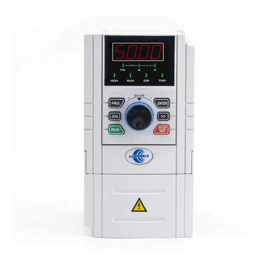
CDE500 Vector Control AC Drive Chapter 4 Operation,Display and Application Chapter 4 Operation,Display and Application 4.1 Keypad Interface Figure 4- 1 LED Keypad (Keypad A) Figure 4- 2 LED and LCD display Keypad (Keypad B) -49-... -
Page 63: Keypad Indicators
AC drive being alarm or fault state ‘*’ Note: Mark means for LED keypad (Keypad A) only. 4.3 Function of the Keypad Key Table 4- 2 Function of the Keypad Key on CDE500 series AC drive Name Function Programming/ 1) Eenter level 1 menu. -
Page 64: Keypad Display
CDE500 Vector Control AC Drive Chapter 4 Operation,Display and Application 4.4 Keypad Display LED screen can only display 4 digits. If the parameter value is more than 4 digits, the display method is shown in the table below. Note: If the parameter can be modified, each digit can be switched by SHIFT key. Table 4- 3 Five digits shown method of LED screen Actual value Display value... -
Page 65: Menu Introduction
CDE500 Vector Control AC Drive Chapter 4 Operation,Display and Application 4.4 Menu Introduction Three level menu: Level 1 : like —b2—, function code group, the group name will display on the LCD screen. Level 2 : like b2.01, function code, the function code name will display on the LCD screen. Level 3 : like 50.00, function code setting value, the value range will display on the LCD screen. -
Page 66: Parameters Upload And Download
CDE500 Vector Control AC Drive Chapter 4 Operation,Display and Application Steps of select monitor parameters. Choose the parameters to be displayed. Sum the value of every parameter bit .Set the summation value to the related parameter. For example,if the Running frequency, Bus voltage, and Pulses Count value need to be displayed, H0.03 shall be set to the summation value of 32773(1+4+32768 = 32773). -
Page 67: Password And Parameter Setting
CDE500 Vector Control AC Drive Chapter 4 Operation,Display and Application 4.7 Password and Parameter Setting The AC drive provides the user password protection function. When H0.00 is set to a non-zero value, the value is the user password. Set H0.00 to the same value for the 2 time in a row,and the password will be set successfully.Meanwhile, the LED will display ‘P.SEt’... -
Page 68: User Defined Parameters
CDE500 Vector Control AC Drive Chapter 4 Operation,Display and Application 4.8 User Defined Parameters Please refer to the parameters description of group P0. 4.9 Non-basic Menu Display Two non-basic menu is determined by H0.05, as shown in the table below. Table 4- 5 Menu display types H0.05 Menu display type... -
Page 69: Chapter 5 Parameter List Table
CDE500 Vector Control AC Drive Chapter 5 Parameter List Table Chapter 5 Parameter List Table The symbols in the parameter list table are described as follows: “”: The parameter cannot be modified when the AC drive is in the running state. Classification Function Code Description... -
Page 70: A0 Monitor
CDE500 Vector Control AC Drive Chapter 5 Parameter List Table Parameter List Table A0 Monitor Function Name Range Default Step Description Code A0.00 Running 0.00~b0.00 0.00 0.01Hz frequency A0.01 Setting frequency 0.00~b0.00 0.00 0.01Hz A0.02 DC bus voltage 0.0~3000.0 0.1V A0.03 Output voltage 0~1500... - Page 71 CDE500 Vector Control AC Drive Chapter 5 Parameter List Table Function Name Range Default Step Description Code A0.18 FI frequency 0.00~100.00 0.00 0.01kHz Display the X6/FI frequency A0.19 FO frequency 0.00~100.00 0.00 0.01kHz Display the Y2/FO high speed pulse output frequency A0.20 PID reference 0.0~100.0...
- Page 72 CDE500 Vector Control AC Drive Chapter 5 Parameter List Table Function Name Range Default Step Description Code A0.33 Encoder -320.00~320.00 0.00 0.01Hz indicate the motor speed from detection speed Encoder detection A0.34 Z pulse counter 0~65535 A0.35 Resolver position 0~4095 A0.36 Reference 0~b0.07...
-
Page 73: A1 Fault & Diagnostics
CDE500 Vector Control AC Drive Chapter 5 Parameter List Table Function Name Range Default Step Description Code A0.59 Motor temperature 0.0~300.0 0.1℃ This value is from PT100/PT1000 optional card. A0.60 Inverter module temperature -40.0~125.0 0.1℃ A0.61 Rectifier module temperature -40.0~125.0 0.1℃... - Page 74 CDE500 Vector Control AC Drive Chapter 5 Parameter List Table Function Name Range Default Step Description Code A1.01 Output frequency upon 0.00~b0.00 0.00 0.01Hz Same As A0.00 1st(latest) fault A1.02 Output current upon1st(latest) 0.00~655.35 0.00 0.01A Same As A0.04 fault A1.03 DC bus voltage upon1st(latest) 0.0~6553.5...
-
Page 75: B0 Basic Parameters
CDE500 Vector Control AC Drive Chapter 5 Parameter List Table Function Name Range Default Step Description Code A1.22 Accumulative running day upon 2nd 0~9999 1Day fault A1.23 Accumulative running hour upon 2nd 0.00~23.99 0.00 0.01h fault A1.24 3rd fault type 0~54 Same As A1.00~A1.11... -
Page 76: B1 Run & Stop Logic
CDE500 Vector Control AC Drive Chapter 5 Parameter List Table Function Name Range Default Step Description Code ① b0.06 Motor rated power 0.1~999.9 Module 0.1kw dependent ① b0.07 Motor rated voltage 1~2000 Module dependent b0.08 ① Motor rated current 0.01~655.35 0.01A ①... -
Page 77: B2 Frequency Source
CDE500 Vector Control AC Drive Chapter 5 Parameter List Table Function Name Range Default Step Description Code b1.14 Stop DC brake waiting time 0.0~100.0 0.1Sec b1.15 Stop DC brake current 0~100 b1.16 Stop DC brake time 0.0~100.0 0.1Sec b1.17 Running mode when running frequency lower than frequency lower limit 0: Run at frequency lower limit... -
Page 78: C0 Digital Input
CDE500 Vector Control AC Drive Chapter 5 Parameter List Table Code Name Range Default Step Description b2.01 Preset Frequency 0.00~b0.00 50.00 0.01Hz ① b2.02 Auxiliary frequency source B Same As b2.00 b2.03 Range of auxiliary frequency 0~100 source B b2.04 Offset frequency for A and B 0.00~b0.00 0.00... - Page 79 CDE500 Vector Control AC Drive Chapter 5 Parameter List Table Function Name Range Default Step Description Code 25: Normally closed (NC) input of 33: Command source switchover 46: Swing pause external fault terminal 2 47: Current running time reset 26: Frequency modification 34: Speed control/torque control 48: Motor 1# interlock input forbidden...
-
Page 80: C1 Digital Output
CDE500 Vector Control AC Drive Chapter 5 Parameter List Table Function Name Range Default Step Description Code C0.17 ① I/O command mode 0: Two-line mode 1 1: Two-line mode 2 2: Three-line mode 1 3: Three-line mode 2 C0.18 UP/DOWN adjustment selection 0: Frequency reference 1: Torque reference... - Page 81 CDE500 Vector Control AC Drive Chapter 5 Parameter List Table Function Name Range Default Step Description Code C1.02 Y2 function 0~45 C1.03 Y3 function 0~45 C1.04 T1 function 0~45 C1.05 T2 function 0~45 Same As C1.01 C1.06 T3 function 0~45 C1.07 T4 function 0~45...
-
Page 82: C2 Analog Input
CDE500 Vector Control AC Drive Chapter 5 Parameter List Table C2 Analog Input Function Name Range Default Step Description Code C2.00 AI1 filter time 0.00~10.00 0.10 0.01Sec C2.01 AI2 filter time 0.00~10.00 0.10 0.01Sec C2.02 AI3 filter time 0.00~10.00 0.10 0.01Sec C2.03 AI curve selection... -
Page 83: C3 Analog Output
CDE500 Vector Control AC Drive Chapter 5 Parameter List Table Function Name Range Default Step Description Code C2.22 Setting for AI less than 000~111 minimum input 0: corresponding to minimum setting 1: 0.0% Unit's digit: AI1 Ten's digit: AI2 Hundred's digit: AI3 C3 Analog Output Function Name... -
Page 84: C4 Pulse Input/Output
CDE500 Vector Control AC Drive Chapter 5 Parameter List Table C4 Pulse Input/Output Function Name Range Default Step Description Code C4.00 FI filter time 0.00~10.00 0.10 0.01Sec C4.01 FI minimum input 0.00~C4.03 0.00 0.01kHz C4.02 Corresponding setting of FI -100.0~100.0 0.1% minimum input C4.03... -
Page 85: D0 Motor Control
CDE500 Vector Control AC Drive Chapter 5 Parameter List Table Function Name Range Default Step Description Code C5.09 ① VY1 function 0~45 Same As C1.01 C5.10 ① VY2 function 0~45 Same As C1.01 ① C5.11 VY3 function 0~45 Same As C1.01 ①... - Page 86 CDE500 Vector Control AC Drive Chapter 5 Parameter List Table Function Name Range Default Step Description Code d0.08 V/f slip compensation gain 0.0~100.0 0.1% d0.09 V/F over-excitation gain 0~250 d0.10 0~500 V/F oscillation suppression gain Module dependent d0.11 Overcurrent stall gain 0~300 Module dependent d0.12...
-
Page 87: D1 Motor Parameters
CDE500 Vector Control AC Drive Chapter 5 Parameter List Table d1 Motor Parameters Function Name Range Default Step Description Code d1.01 ① Motor stator Module Module 0.001ohm resistance dependent dependent ① d1.02 Motor rotor Module Module 0.001ohm resistance dependent dependent d1.03 ①... - Page 88 CDE500 Vector Control AC Drive Chapter 5 Parameter List Table Function Name Range Default Step Description Code d2.09 Upper torque limit Source of forward motoring 0: d2.10 2: AI2 4: X6/FI 6: MIN(AI1,AI2) 1: AI1 3: AI3 5: Communication 7: MAX(AI1,AI2) d2.10 Preset upper torque limit of 0.0~300.0...
-
Page 89: D3 Torque Control
CDE500 Vector Control AC Drive Chapter 5 Parameter List Table d3 Torque Control Function Name Range Default Step Description Code d3.00 ① Speed/Torque control 0: Speed Control selection 1: Torque Control ① d3.01 Torque reference source 0: d3.02+UP/DOWN 2: AI2 4: X6/FI 6: MIN(AI1,AI2)... -
Page 90: D5 Motor 2 Parameters
CDE500 Vector Control AC Drive Chapter 5 Parameter List Table Function Name Range Default Step Description Code d3.13 Dynamic torque 0.0~100.0 0.1% compensation d3.14 Inertia torque 0.0~100.0 0.1% compensation d3.15 Torque acceleration time 0.00~650.00 2.00 0.01Sec d3.16 Torque deceleration 0.00~650.00 2.00 0.01Sec time... -
Page 91: D6 Motor 2 Speed Control
CDE500 Vector Control AC Drive Chapter 5 Parameter List Table Function Name Range Default Step Description Code d5.14 ① Motor 2 weaken flux 0.000~1.000 1.000 0.001 Flux weakening coefficient 2 coefficient at 50% flux current ① d5.15 Motor 2 weaken flux 0.000~1.000 1.000 0.001... - Page 92 CDE500 Vector Control AC Drive Chapter 5 Parameter List Table Function Name Range Default Step Description Code d6.11 Motor 2 Upper torque limit Source of reverse motoring 0: d6.12 2: AI2 4: X6/FI 6: MIN(AI1,AI2) 1: AI1 3: AI3 5: Communication 7: MAX(AI1,AI2)...
-
Page 93: E0 Jog
CDE500 Vector Control AC Drive Chapter 5 Parameter List Table E0 JOG Function Name Range Default Step Description Code E0.00 JOG frequency 0.00~b0.00 5.00 0.01Hz E0.01 JOG acceleration time 0.1~6000.0 10.0 0.1Sec E0.02 JOG deceleration time 0.1~6000.0 10.0 0.1Sec E0.03 JOG stop mode 0: Ramp stop 1: Coasting stop... -
Page 94: E3 Simple Plc
CDE500 Vector Control AC Drive Chapter 5 Parameter List Table E3 Simple PLC Function Name Range Default Step Description Code E3.00 Simple PLC running mode 0: Stop after the AC drive running one cycle 2: Repeat after the AC drive running one cycle 1: Keep final values after the AC drive running one cycle E3.01 Simple PLC retentive selection... -
Page 95: E4 Acc & Dec Time
CDE500 Vector Control AC Drive Chapter 5 Parameter List Table Function Name Range Default Step Description Code E3.27 0.0~6553.5 0.1Sec Running time of simple PLC reference 12 E3.28 Same As E3.04 Acc/dec time of simple PLC reference 12 E3.29 0.0~6553.5 0.1Sec Running time of simple PLC reference 13 E3.30... -
Page 96: E5 Pid
CDE500 Vector Control AC Drive Chapter 5 Parameter List Table E5 PID Function Name Range Default Step Description Code ① E5.00 PID engineering unit 0:Percentage(%) 1:Pressure(MPa) 2:Centigrade(℃) 3:Kilowatt(kW) 4:Kilowatt hour(kWh) 5:Flow(m E5.01 PID engineering unit resolution 0: No decimal 1: One decimal 2: Two decimals 3: Three decimals Maximum setting of PID... - Page 97 CDE500 Vector Control AC Drive Chapter 5 Parameter List Table Function Name Range Default Step Description Code E5.25 Cut-off frequency of PID 0.00~b0.00 0.00 0.01Hz reverse rotation E5.26 PID deviation limit 0.0~100.0 0.1% Base on PID setting value E5.27 PID deviation limit delay time 0.0~320.0 0.1Sec E5.28...
-
Page 98: E6 Multi-Pump Control
CDE500 Vector Control AC Drive Chapter 5 Parameter List Table E6 Multi-Pump Control Function Name Range Default Step Description Code ① E6.00 Multi-pump control mode This series AC drive support multi pump control modes. Each of them is apply to different application area with specific configuration and operation logic. -
Page 99: E7 Swing Frequency
CDE500 Vector Control AC Drive Chapter 5 Parameter List Table E7 Swing Frequency Function Name Range Default Step Description Code E7.00 Swing frequency 0: reference to setting frequency setting mode 1: reference to max frequency E7.01 Swing frequency 0.0~100.0 0.1% amplitude E7.02 Skip frequency... -
Page 100: Ea External Brake
CDE500 Vector Control AC Drive Chapter 5 Parameter List Table EA External Brake Function Name Range Default Step Description Code ① EA.00 External brake control enable 0: Inactive 1: active ① EA.01 External brake off frequency limit 0.00~10.00 2.50 0.01Hz EA.02 ①... - Page 101 CDE500 Vector Control AC Drive Chapter 5 Parameter List Table Function Name Range Default Step Description Code Eb.11 Any frequency reaching 0.00~b0.00 50.00 0.01Hz detection value 2 Eb.12 Any frequency reaching 0.0~100.0 0.1% detection amplitude 2 Eb.13 frequency detection 0.00~b0.00 50.00 0.01Hz threshold 1 (FDT1)
-
Page 102: F0 Protection
CDE500 Vector Control AC Drive Chapter 5 Parameter List Table F0 Protection Function Name Range Default Step Description Code F0.00 Under voltage threshold Module 0.1V Module dependent dependent ① F0.01 Over voltage threshold Module 0.1V Module dependent dependent F0.02 Input phase loss protection 0: Disabled 1: Enabled F0.03... - Page 103 CDE500 Vector Control AC Drive Chapter 5 Parameter List Table Function Name Range Default Step Description Code F0.20 Fault protection action selection 2 0000~2222 0000 Unit's digit: motor underload 0: Coasting stop 2: Jump to 8% motor rated frequency, resume to 1: Stop by stop mode setting frequency when underload is inactive.
-
Page 104: F1 Auto Reset
CDE500 Vector Control AC Drive Chapter 5 Parameter List Table F1 Auto Reset Code Name Range Default Step Description F1.00 Fault auto reset times 0~30 F1.01 Time interval of fault auto reset 0.1~100.0 0.1Sec F1.02 DO action during fault auto reset 00~11 Unit's digit: Fault indication terminals 0: No action during fault reset process... - Page 105 CDE500 Vector Control AC Drive Chapter 5 Parameter List Table Code Name Range Default Step Description H0.06 Function code lock 0:Disabled 1:Enabled H0.07 Accumulative power 0~9999 on time lock password H0.08 0.001~9.999 0.300 0.001 Load speed display coefficient H0.09 Load speed display decimal digits ①...
-
Page 106: H1 Ai/Ao Calibration
CDE500 Vector Control AC Drive Chapter 5 Parameter List Table H1 AI/AO Calibration Function Name Range Default Step Description Code H1.00 AI1 actual voltage 1 0.500~4.000 Factory setting 0.001V H1.01 AI1 display voltage 1 0.500~4.000 Factory setting 0.001V H1.02 AI1 actual voltage 2 6.000~9.999 Factory setting 0.001V... -
Page 107: L1 Point-Point Communication
CDE500 Vector Control AC Drive Chapter 5 Parameter List Table L1 Point-point Communication Function Name Range Default Step Description Code L1.00 ① Master and slave selection 0: Master 1: Slave ① L1.01 Send data selection 0: Torque reference master 1: Running frequency 2: Setting frequency 3: Feedback frequency ①... -
Page 108: P0 User-Defined Parameters
CDE500 Vector Control AC Drive Chapter 5 Parameter List Table Function Name Range Default Step Description Code L2.10 ① Motor 2 Encoder pulse per revolution 1~65535 1024 L2.11 ① Motor 2 A/B phase sequence of ABC Same As L2.02 incremental Encoder ①... -
Page 109: Chapter 6 Parameters Description
CDE500 Vector Control AC Drive Chapter 6 Parameters Description Chapter 6 Parameters Description Group A0: Monitor Parameters in A0 group are used to facilitate the user to view the drive state, all of these parameters are read only, users can’t modify them. When using the keypad to view these parameters, the keypad will refresh these values. - Page 110 CDE500 Vector Control AC Drive Chapter 6 Parameters Description A0.08 Range: 0.00~b0.00 Default: 0.00 Main frequency A Unit: Hz It displays the setting of main frequency A. A0.09 Range: 0.00~b0.00 Default: 0.00 Auxiliary Unit: Hz frequency B It displays the setting of auxiliary frequency B. A0.10 Range: 0~65535 Default: 0...
- Page 111 CDE500 Vector Control AC Drive Chapter 6 Parameters Description A0.12 Range: -10.00~10.00 Default: 0.00 AI2 voltage Unit: V It display AI2 voltage, the covert mode same as A0.11. A0.13 Range: -10.00~10.00 Default: 0.00 AI3 voltage Unit: V It display AI3 voltage, the covert mode same as A0.11. A0.14 Range: 0.00~10.00 Default: 0.00...
- Page 112 CDE500 Vector Control AC Drive Chapter 6 Parameters Description A0.20 Range: 0.0~100.0 Default: 0.0 PID setting Unit: %, the unit is equal to engineering unit. They display the PID setting value. System use the unit of percent in PID internal calculation. For better of display the PID setting value, system will convert the value to engineering unit value.
- Page 113 CDE500 Vector Control AC Drive Chapter 6 Parameters Description A0.26 Range: 0~65535 Default: 0 Actual length Unit: m It display value of A0.25 divide to E7.08, it is used for fixed length control. A0.27 Range: 0.0~6553.5 Default: 0.0 Linear speed Unit: m/Min It displays value of sample number at every minute divide to E7.08.
- Page 114 CDE500 Vector Control AC Drive Chapter 6 Parameters Description A0.34 Range: 0~65535 Default: 0 Phase z counting It displays the phase Z counting of the current ABZ or UVW encoder. The value increases or decreases by 1 every time the encoder rotates one revolution forwardly or reversely.
- Page 115 CDE500 Vector Control AC Drive Chapter 6 Parameters Description A0.53 Range: 0.0~6553.5 Default: 0.0 Running time Unit: Min It is used to display the current running time of the drive, the unit is 0.1 minute. A0.54 Range: 0~9999 Default: 0 Accumulative Unit: Day power-on day...
-
Page 116: Group A1: Fault & Diagnostic
CDE500 Vector Control AC Drive Chapter 6 Parameters Description Group A1: Fault & Diagnostic A1.00 Range: 0~54 Default: 0 Latest fault type It display the fault type upon latest fault. The characters of “Er” and fault code are displayed in LED. The relationship of fault code and fault type are described in the following table, the detail about the alarm and run mode are in Chapter 7. - Page 117 CDE500 Vector Control AC Drive Chapter 6 Parameters Description A1.01 Range: 0.00~b0.00 Default: 0.00 Output frequency Unit: Hz upon latest fault Same as A0.00 A1.02 Range: 0.00~655.35 Default: 0.00 Output current Unit: A upon latest fault Same as A0.04 A1.03 Range: 0.0~6553.5 Default: 0.0 Dc-link voltage...
-
Page 118: Group B0: Basic Parameters
CDE500 Vector Control AC Drive Chapter 6 Parameters Description running hour Total accumulative running time upon latest fault is A1.10+A1.11 upon latest fault The parameters of A1.12~A1.23 are the penultimate fault record, the mean of these parameters same as A1.00~A1.11 The parameters of A1.24~A1.35 are the third fault record, the mean of these parameters same as A1.00~A1.11 Group b0: Basic Parameters... - Page 119 CDE500 Vector Control AC Drive Chapter 6 Parameters Description from 0 Hz to E4.09, please see the T1 in the following figure. b0.05 Range: 0.1~6000.0 Default: Model dependent Deceleration Unit: Sec time 1 Deceleration time indicates the time required by the drive to decelerate from E4.09 to 0 Hz, please see the T2 in the following figure.
- Page 120 CDE500 Vector Control AC Drive Chapter 6 Parameters Description ① b0.10 Range: 1~65535 Default: 1460 Motor rated Unit: RPM speed The default value of this parameter is estimated based on the motor which have four poles. Please set according to the motor nameplate data. Note: both the VF and vector control, in order to ensure the control performance, please be sure to follow the actual motor nameplate data set the correct values of b0.06~b0.10 parameters.
- Page 121 CDE500 Vector Control AC Drive Chapter 6 Parameters Description C0.03 X3 function 48: Motor 1# interlock input C0.04 X4 function 49: Motor 2# interlock input UP/DOWN adjustment C0.18 2: PID reference 2: PID reference selection C1.04 T1 function 40: Motor 1# control output C1.05 T2 function 38: PID sleep status indication...
-
Page 122: Group B1: Run & Stop Logic
CDE500 Vector Control AC Drive Chapter 6 Parameters Description Group b1: Run & Stop Logic ① b1.00 Range: 0~1 Default: 0 Acceleration It is used to set the frequency change mode during the drive start and /Deceleration stop process mode 0: Linear The output frequency increases or decreases in linear mode, please see the following figure. - Page 123 CDE500 Vector Control AC Drive Chapter 6 Parameters Description b1.03 Range: 0.00~50.00 Default: 0.00 Startup Unit: Hz frequency Start frequency is the initial frequency of drive from stop to start. It not restricted by lower frequency limit. If setting frequency less than startup frequency, the drive will run with the frequency of zero.
- Page 124 CDE500 Vector Control AC Drive Chapter 6 Parameters Description ① b1.06 Range: 0~2 Default: 0 Flying start mode To complete the rotational speed tracking process within the shortest time, select the proper mode in which the drive tracks the motor rotational speed.
- Page 125 CDE500 Vector Control AC Drive Chapter 6 Parameters Description ① b1.12 Range: 0.0~100.0 Default: 0.0 Start DC brake Unit: Sec time This parameter specifies DC brake time when drive startup. If the startup DC braking time is 0, the drive starts directly without DC braking. b1.13 Range: 0.00~b0.00 Default: 0.00...
- Page 126 CDE500 Vector Control AC Drive Chapter 6 Parameters Description Figure 6- 6 Stop DC brake b1.17 Range: 0~3 Default: 0 Running mode The parameter determined drive action when setting frequency lower than when running frequency lower limit. frequency lower 0: Run at frequency lower limit than frequency 1: Run at zero speed lower limit...
- Page 127 CDE500 Vector Control AC Drive Chapter 6 Parameters Description b1.19 Range: 0.0~3000.0 Default: 0.0 Forward/Reverse Unit: s rotation It is used to set the time when the output is 0Hz at transition of the drive dead-zone time forward rotation and reverse rotation, as shown in the following figure. Figure 6- 7 Forward/reverse rotation dead-zone time b1.20 Range: 0~1...
- Page 128 CDE500 Vector Control AC Drive Chapter 6 Parameters Description b1.23 Range: 0~100 Default: 100 Dynamic brake Unit: % use ratio The larger the value of this parameter is, the better the braking result will be. However, too larger value causes great fluctuation of the drive bus voltage during the braking process.
-
Page 129: Group B2: Frequency Source
CDE500 Vector Control AC Drive Chapter 6 Parameters Description Group b2: Frequency Source b2.00 ① Range: 0~8 Default: 0 Main frequency It is used to select the setting channel of the main frequency A. You can source A set the main frequency in the following 9 channels: 0: Digital setting b2.01+UP/DOWN The initial value of the set frequency is the value of b2.01(Preset frequency). - Page 130 CDE500 Vector Control AC Drive Chapter 6 Parameters Description 7: Multi-reference In multi-reference mode, combinations of different DI terminal states correspond to different set frequencies. The AC drive supports a maximum of 16 speeds implemented by 16 state combinations of four DI terminals (allocated with functions 16 to 19) from E2.01 to E2.16.
- Page 131 CDE500 Vector Control AC Drive Chapter 6 Parameters Description b2.05 Range: 00~34 Default: 00 Frequency Unit's digit: Frequency source selection source selection 0: Main frequency source A. 1: A and B operation The result of A and B operate as the aim frequency, the operate relationship determined by ten's digit of the parameter.
- Page 132 CDE500 Vector Control AC Drive Chapter 6 Parameters Description b2.06 Range: 000~999 Default: 000 Binding It is used to bind the three running command sources with the nine command source frequency sources, facilitating to implement synchronous switchover. to frequency Unit's digit: Binding the frequency source together with Keypad source control source 0: No binding...
-
Page 133: Group C0: Digital Input
CDE500 Vector Control AC Drive Chapter 6 Parameters Description Group C0: Digital Input C0.00 Range: 0.000~1.000 Default value: 0.010 X terminals filter Unit: Sec time X1~X10(X6/FI act as common terminal usage)sample filter time setting. Appropriate to adjustment the filter time can increase the terminal input signal ability of anti-interference, prevent the miss-operation;... - Page 134 CDE500 Vector Control AC Drive Chapter 6 Parameters Description Setting Function Description Under any control mode(b0.11 is an arbitrary value), the configuration of External STOP this function can make the AC drive stopped according to the stop mode. terminal 2 This deceleration time is fixed for E4.05(deceleration time 4).
- Page 135 CDE500 Vector Control AC Drive Chapter 6 Parameters Description Setting Function Description Terminal 1 for Through the X terminal configuration of these two functions, combination of Acceleration up to 4 kinds of acceleration and deceleration time, as shown in the /decelerat-ion following table.
- Page 136 CDE500 Vector Control AC Drive Chapter 6 Parameters Description Setting Function Description The configuration of this function can select the current load motor. When Motor 1/2 swtichover the terminal is invalid, select the motor 1;When the terminal is valid, select the motor 2.
- Page 137 CDE500 Vector Control AC Drive Chapter 6 Parameters Description Setting Function Description Through the configuration of this function, can realize the switch over Speed control/torque speed control and torque control. Only the vector control support torque control switchover control. Torque control If the configuration of this function is effective, the AC drive force to speed prohibited control.
- Page 138 CDE500 Vector Control AC Drive Chapter 6 Parameters Description Setting Function Description Through the configuration of the pulse length count function, AC drive can calculate the actual length for fixed length control. The current length value length Count input can be saved when power off. When the frequency is high, you must use the X6/FI.
- Page 139 CDE500 Vector Control AC Drive Chapter 6 Parameters Description Note: 1. The priority of frequency source is Fire mode >JOG >Frequency bind >Force to >Force to PLC >Force to digit set >Multi speed >Configuration of main and auxiliary frequency source parameter configuration. 2.
- Page 140 CDE500 Vector Control AC Drive Chapter 6 Parameters Description ① C0.06 Range: 0~58 Default: 0 X6 function Same as C0.01. C0.07 ① Range: 0~58 Default: 0 X7 function Same as C0.01. C0.08 ① Range: 0~58 Default: 0 X8 function Same as C0.01. ①...
- Page 141 CDE500 Vector Control AC Drive Chapter 6 Parameters Description C0.15 Range: 0.0~3000.0 Default: 0.0 X2 terminal Unit: Sec delay time Delayed response time to set the X2 terminal of the input signal C0.16 Range: 0.0~3000.0 Default: 0.0 X3 terminal Unit: Sec delay time Delayed response time to set the X3 terminal of the input signal Through the C0.14~C0.16 three parameters, you can set the X1~X3 terminal input...
- Page 142 CDE500 Vector Control AC Drive Chapter 6 Parameters Description Example 1: Two lines 1. Terminal X1 controls forward run, and X2 controls reverse run. The parameters’ configuration show as following table. Table 6- 6 Two lines 1 parameters’ configuration Parameter Setting C0.17(Terminal command mode) 0(Two lines 1)...
- Page 143 CDE500 Vector Control AC Drive Chapter 6 Parameters Description The wiring is shown in the following figure. Among them: If K1 closed, K2 broken open the AC drive run forward, K2 closed the AC drive run reverse; If K1 broken open, the AC drive stop running. Both X1 and X2 are level effective.
- Page 144 CDE500 Vector Control AC Drive Chapter 6 Parameters Description Figure 6- 11 Three lines 1 Example 4: Three lines 2. X1 determines whether to run,X2 determines run direction,X3 determines run enable. The parameters’ configuration is shown as the table below.. Table 6- 9 Three lines 2 parameters’...
-
Page 145: Group C1: Digital Output
CDE500 Vector Control AC Drive Chapter 6 Parameters Description C0.18 Range: 0~2 Default: 0 UP/DOWN 0: Frequency reference Regulation When b2.00(Frequency source A selection) or b2.02(Auxiliary chose frequency source B selection) is set to 0(digital setting b2.01 + UP/DOWN set), terminal UP/DOWN and keypad regulation will be superposed to b2.01, the superposition of the results will be the given of main frequency source A or auxiliary frequency source B. - Page 146 CDE500 Vector Control AC Drive Chapter 6 Parameters Description Table 6- 10 Switch input and output function table Setting Function Description No output The output terminal is invalid, and not output signal. When the bus voltage is below the under voltage level, the terminal Under voltage output “ON”...
- Page 147 CDE500 Vector Control AC Drive Chapter 6 Parameters Description Setting Function Description When the A0.60(AC drive temperature) is greater than or equal to Module temperature Eb.27(Module temperature reaches the set value), the terminal output reached ON signal. When A0.59(The temperature of the motor) is greater than or equal to Motor Over heat F0.14(Motor overheat warning threshold), the terminal output ON pre-warning...
- Page 148 CDE500 Vector Control AC Drive Chapter 6 Parameters Description Setting Function Description When the input voltage of AI1 is less than Eb.25(AI1 input voltage AI1 input limit exceeded lower limit), or greater than Eb.26(AI1 input voltage upper limit), the terminal output ON signal. Reference to Eb.00(...
- Page 149 CDE500 Vector Control AC Drive Chapter 6 Parameters Description C1.06 Range: 0~45 Default: 0 T3 Function Defines the functions of rely T3, same as C1.01. C1.07 Range: 0~45 Default: 0 T4 Function Defines the functions of rely T4, same as C1.01. C1.08 Range: 0~45 Default: 0...
- Page 150 CDE500 Vector Control AC Drive Chapter 6 Parameters Description Figure 6- 13 digital output terminals output delay time diagram. C1.14 Range: 0.0~3000.0 Default: 0.0 Y2 output delay Unit: Sec time Define the output delay time of output switch terminal Y2. C1.15 Range: 0.0~3000.0 Default: 0.0...
-
Page 151: Group C2: Analog Input
CDE500 Vector Control AC Drive Chapter 6 Parameters Description C1.22 Range: 0.0~600.0 Default: 0.0 Interval of Y1 Unit: Sec output active Define the digital output terminal Y1 output effective sate holdoff time.. state C1.23 Range: 0.0~600.0 Default: 0.0 Interval of Y2 Unit: Sec output active Define the digital output terminal Y2 output effective sate holdoff time. - Page 152 CDE500 Vector Control AC Drive Chapter 6 Parameters Description Figure 6- 15 figure of AI signal filter C2.01 Range: 0.00~10.00 Default: 0.10 AI2 filter time Unit: Sec Define the filter time of AI2 signal, to filter processing. C2.02 Range: 0.00~10.00 Default: 0.10 AI3 filter time Unit: Sec...
- Page 153 CDE500 Vector Control AC Drive Chapter 6 Parameters Description C2.07 Range: -100.0~100.0 Default: 100.0 Corresponding Unit: % setting of AI The relationship between AI curve 1 maximal input signal and the curve 1 maximal percentage of set value. input C2.08 Range: -10.00~C2.10 Default: 0.00 AI curve 2...
- Page 154 CDE500 Vector Control AC Drive Chapter 6 Parameters Description Figure 6- 16 AI curve 1/2 normal setting C2.12 Range: -10.00~C2.14 Default: 0.00 AI curve 3 Unit: V minimum input AI curve 3minimal input signal size C2.13 Range: -100.0~100.0 Default: 0.0 Corresponding Unit: % setting of AI...
- Page 155 CDE500 Vector Control AC Drive Chapter 6 Parameters Description C2.17 Range: 0.0~100.0 Default: 0.5 Jump amplitude Unit: % of AI1 input corresponding Jump amplitude of AI1 input corresponding setting setting C2.18 Range: -100.0~100.0 Default: 0.0 Jump point of AI2 Unit: % input corresponding Jump point of AI2 input corresponding setting.
-
Page 156: Group C3: Analog Output
CDE500 Vector Control AC Drive Chapter 6 Parameters Description lower than the minimum input, the corresponding setting is decided by the minimum input corresponding setting(C2.05,C2.09). 1: 0.0% ; When the AI signal is lower than the minimum input, the corresponding setting is 0%. Unit’s digit: AI1 Ten’s digit: AI2 Hundred’s digit: AI3... - Page 157 CDE500 Vector Control AC Drive Chapter 6 Parameters Description Table 6- 11 Relation table of analog value and pulse output Value Function Range Setting frequency 0~Max frequency(b0.00) Running frequency 0~Max frequency(b0.00) 0~2 times motor rated current Output current Output voltage 0~1.2 times motor rated voltage Output power 0~2 times motor rated power...
- Page 158 CDE500 Vector Control AC Drive Chapter 6 Parameters Description C3.07 Range: 0.00~10.00 Default: 10.00 AO curve 1 Unit: V maximum output AO curve 1 maximal input signal. C3.08 Range: C3.06~100.0 Default: 100.0 Corresponding Unit: % setting of AO The relationship between AO curve 1 maximal input signal and the curve 1 percentage of set value.
-
Page 159: Group C4: Pulse Input/Output
CDE500 Vector Control AC Drive Chapter 6 Parameters Description C3.11 Range: 0.00~10.00 Default: 10.00 AO curve 2 Unit: V maximum output Define AO curve 2 maximal output value. When chose the 0~20mA current input, 0mA corresponding to the 0V, and 20mA corresponding to 10V. - Page 160 CDE500 Vector Control AC Drive Chapter 6 Parameters Description C4.02 Range: -100.0~100.0 Default: 0.0 Corresponding Unit: % setting of FI The percent of corresponding to pulse minimum input frequency. minimum input C4.03 Range: C4.01~100.00 Default: 50.00 FI maximum Unit: kHz input If the pulse input higher C4.03 then it will be limited by C4.03.
-
Page 161: Group C5 : Virtual Digital Input/Output
CDE500 Vector Control AC Drive Chapter 6 Parameters Description Group C5 Virtual Digital Input/Output Virtual terminals can be useful in some applications such as input terminal signal is determined by output terminal. User can connect the virtual outputs with virtual inputs without actual wires. The usage method is similar with actual terminal. - Page 162 CDE500 Vector Control AC Drive Chapter 6 Parameters Description C5.07 ① Range: C5.08~8.00 Default: 6.70 Unit: V AI high level This defines the threshold voltage that AI treated as high level should be threshold greater than. C5.08 ① Range: 1.00~C5.07 Default: 3.20 Unit: V AI low level...
-
Page 163: Group D0: Motor Control
CDE500 Vector Control AC Drive Chapter 6 Parameters Description Group d0: Motor Control ① d0.00 Range: 0 ~ 2 Default: 0 Motor control 0: V/f mode Constant Volt/Hertz proportion control. It is applicable to applications with low load requirements or applications where one AC drive operates multiple motors, such as fan and pump. - Page 164 CDE500 Vector Control AC Drive Chapter 6 Parameters Description Table 6- 12 default carrier frequency and range Volt Grade Power Grade carrier frequency Range ≤ 2.2KW 1.0kHz - 12.0kHz Single-phase 220V 3.7~5.5KW 1.0kHz - 12.0kHz Three-phase 220V Three-phase 380V 7.5~15KW 1.0kHz - 10.0kHz Three-phase 480V ≥...
- Page 165 CDE500 Vector Control AC Drive Chapter 6 Parameters Description d0.06 Range: 0 ~ 30% Default: Model dependent Torque boost 0: auto torque boost >0: fixed torque boost When this parameter is set to 0, output voltage shall be adjust automatically based on the changing of the load. When this parameter is greater than 0, the value that output voltage increase shall be depend on this setting.
- Page 166 CDE500 Vector Control AC Drive Chapter 6 Parameters Description d0.12 Range: 30% ~ 200% Default: 150% Overcurrent stall It used to determine the point that overcurrent stall function is active. The protective based value is rated motor current. current Note: "d0.12 * the motor rated current" generally can not be greater than "d0.32 *the AC drive rated current of G type".
- Page 167 CDE500 Vector Control AC Drive Chapter 6 Parameters Description Table 6- 13 the default value and range of overvoltage stall protective voltage Volt Grade default Range 350 V 330V - 380V Single-phase 220V Three-phase 220V 350 V 330V - 380V Three-phase 380V 680 V 630V - 770V...
- Page 168 CDE500 Vector Control AC Drive Chapter 6 Parameters Description 7: V/f complete separation Output frequency and output voltage are independent. Output frequency is from frequency source, and output voltage is set by d0.21. This V/f curve can be used in applications such as induction heating, inverse power supply and torque motor control.
- Page 169 CDE500 Vector Control AC Drive Chapter 6 Parameters Description ① d0.23 Range: 0.0 ~ 100.0 Default: 100.0 Multi- point V/f Unit: % voltage 3 Multi-point V/f V3 When V/f curve selection (d0.16) is set to 1, output voltage characteristic is determined by the settings of d0.17 ~ d0.23.
- Page 170 CDE500 Vector Control AC Drive Chapter 6 Parameters Description d0.25 Range: 0 ~(b0.07) Default: 0 Voltage digital Unit: V setting for V/f Voltage digital setting for V/f separation. separation d0.26 Range: 0.0 ~ 1000.0 Default: 0.0 Voltage ramp Unit: Sec time of V/f This defines the time required for voltage to change from 0 to rated separation...
-
Page 171: Group D1: Motor Parameters
CDE500 Vector Control AC Drive Chapter 6 Parameters Description Group d1: Motor Parameters ① d1.01 Range: 0.001 ~ 65.535(drive power<=55kW) Default: Model dependent motor stator 0.0001 ~ 6.5535(drive power >55kW) resistance Unit: Ω asynchronous motor stator resistance. ① d1.02 Range: 0.001 ~ 65.535(drive power <=55kW)... - Page 172 CDE500 Vector Control AC Drive Chapter 6 Parameters Description Note: Parameters of d1.01~1.05 will be used when motor type is set as asynchronous motor. Please edit parameters of d1.01~d1.05 if you got the parameters of asynchronous motor. Parameters of d1.01~1.05 can be get from running No-load dynamic auto-tune. ...
-
Page 173: Group D2: Speed Control
CDE500 Vector Control AC Drive Chapter 6 Parameters Description Group d2: Speed Control d2.00 Range: 1 ~ 100 Default: 30 ASR proportional Speed control loop proportional gain (Kp1) in low speed situation. gain Kp1 d2.01 Range: 0.01 ~ 10.00 Default: 0.50 ASR integration Unit: Sec time Ti1... - Page 174 CDE500 Vector Control AC Drive Chapter 6 Parameters Description are obtained from the linear switchover between the two groups of controller parameters, as shown in Fig6-D4. Figure 6- 23 Relationship between running frequencies and speed loop Kp & Ti Note: Improper controller parameter setting may cause overvoltage or over current trip.
- Page 175 CDE500 Vector Control AC Drive Chapter 6 Parameters Description d2.10 Range: 0.0 ~ 300.0 Default: 150.0 Preset upper Unit: % torque limit of When d2.09 is set to 0, this parameter is used as upper torque limit when forward motoring the motor is running forward in motoring mode.
- Page 176 CDE500 Vector Control AC Drive Chapter 6 Parameters Description d2.14 Range: 0.0 ~ 300.0 Default: 150.0 Preset upper Unit: % torque limit of When d2.13 is set to 0, this parameter is used as upper torque limit when forward the motor is running forward in generating mode. If the torque upper limit is generating analog, pulse or communication setting, 100% of the setting corresponds to the value of d2.14, and 100% of the value of d2.14 corresponds to the...
- Page 177 CDE500 Vector Control AC Drive Chapter 6 Parameters Description d2.17 Range: 0 ~ 60000 Default: 2000 Proportional gain of flux current Proportional gain of flux current loop. loop d2.18 Range: 0 ~ 60000 Default: 800 Integration time of flux current Integration time of flux current loop.
-
Page 178: Group D3 : Torque Control
CDE500 Vector Control AC Drive Chapter 6 Parameters Description Group d3 Torque Control d3.00 ① Range: 0 ~ 1 Default: 0 Speed/Torque It is used to select motor control mode in vector control. control selection 0: Speed Control 1: Torque Control If one of the input digital terminals is set to function 35 (torque control forbidden), speed control will be active when the terminal is active regardless the setting of d3.00. - Page 179 CDE500 Vector Control AC Drive Chapter 6 Parameters Description d3.04 Range: -300.0 ~ 300.0 Default: 0.0 Digital setting of Unit: % torque Digital setting of torque compensation. 100% of the setting corresponds to compensation the rated motor torque. Figure 6- 25 torque reference for torque control ①...
- Page 180 CDE500 Vector Control AC Drive Chapter 6 Parameters Description d3.07 Range: -b0.00 ~b0.00 Default: 50.00 Digital setting of Unit: Hz Maximum Digital setting of maximum frequency. frequency d3.08 ① Range: 0 ~ 7 Default: 0 Minimum 0: d3.09 frequency source 1: AI1 2: AI2 3: AI3...
- Page 181 CDE500 Vector Control AC Drive Chapter 6 Parameters Description When d3.05 is set to 1 (Minimum frequency to running frequency), speed limit mode is shown Fig6-D8 Figure 6- 27 d3.05=1 Minimum frequency to running frequency When d3.05 is set to 2 (Negative running frequency to positive running frequency), speed limit mode is shown by Fig6-D9: Figure 6- 28 d3.05=2 Negative running frequency to positive running frequency When d3.05 is set to 3 (Running frequency to maximum frequency), speed limit mode is shown...
- Page 182 CDE500 Vector Control AC Drive Chapter 6 Parameters Description When d3.05 is set to 4 (Running frequency + windows), speed limit mode is shown by Fig6-D11: Figure 6- 30 d3.05=4 Running frequency + windows When d3.05 is set to 5 (0Hz to running frequency), speed limit mode is shown byFig6-D12: Figure 6- 31 d3.05=5 0Hz to running frequency d3.12 Range: 0.0 ~ 100.0...
-
Page 183: Group D5: Motor 2 Parameters
CDE500 Vector Control AC Drive Chapter 6 Parameters Description 0 to rated motor torque. d3.16 Range: 0.00 ~ 650.00 Default: 2.00 Torque Unit: Sec deceleration time This defines the time required for actual torque reference to change from 0 to rated motor torque. d3.17 Range: -300.0~300.0 Default: 150.0... - Page 184 CDE500 Vector Control AC Drive Chapter 6 Parameters Description ① d5.04 Range: 1 ~ 2000 Default: Model dependent Motor 2 rated Unit: V voltage motor 2 rated voltage ① d5.05 Range: Motor 2 rated 0. 01 ~ 655.35(drive power<=55kW) Default: Model dependent current 0.
-
Page 185: Group D6: Motor 2 Speed Control
CDE500 Vector Control AC Drive Chapter 6 Parameters Description d5.12 ① Range: 0.01 ~ motor rated current Default: Model dependent Motor 2 no-load (b0.08)(drive power <=55kW) current Unit: A asynchronous motor no-load 2 current. d5.13 ① Range: 0.000 ~ 1.000 Default: 0.400 Motor 2 weaken The flux coefficient corresponds to 20% of flux current. - Page 186 CDE500 Vector Control AC Drive Chapter 6 Parameters Description d6.04 Range: Default: 5.00 Motor 2 Low 0.00 ~ switchover frequency2(d2.05) speed switchover Unit: Hz frequency switchover frequency1 d6.05 Range: Switchover Frequency 1 Default: 10.00 Motor 2 High (d2.04) ~ Max Frequency(b0.00) speed switchover Unit: Hz frequency...
- Page 187 CDE500 Vector Control AC Drive Chapter 6 Parameters Description d6.11 Range: 0 ~ 7 Default: 0 Motor 2 Upper 0: d2.10 2: AI2 4: X6/FI 6: MIN(AI1,AI2) torque limit 1: AI1 3: AI3 5: Communication 7: MAX(AI1,AI2) Source of This parameter allows user to select the desired source as upper torque to reverse motoring limit the motor output torque when the motor is running reverse in motoring mode.
-
Page 188: Group E0: Jog
CDE500 Vector Control AC Drive Chapter 6 Parameters Description d6.17 Range: 0 ~ 60000 Default: 2000 Motor 2 Proportional gain of flux current loop. Proportional gain of flux current loop d6.18 Range: 0 ~ 60000 Default: 800 Motor 2 Integration Integration time of flux current loop. -
Page 189: Group E1: Skip Frequency
CDE500 Vector Control AC Drive Chapter 6 Parameters Description E0.03 Range: 0~1 Default: 0 JOG stop mode 0: Ramp stop 1: Coasting stop E0.04 Range: 0~1 Default: 0 JOG preferred When set E0.04 to 1,the AC drive will response the JOG command of current control source immediately even if in running state.And the JOG command form other control source will be ignored. -
Page 190: Group E2: Multi-Reference
CDE500 Vector Control AC Drive Chapter 6 Parameters Description Group E2: Multi-Reference The AC drive multi-reference has many functions. Besides multi-speed, it can be used as the setting source of the V/F separated voltage source and setting source of process PID. The multi-reference is frequency value and ranges from -b0.00 to b0.00. -
Page 191: Group E3: Simple Plc
CDE500 Vector Control AC Drive Chapter 6 Parameters Description Group E3: Simple PLC Simple PLC can complete simple combination of multi-reference. E3.00 Range: 0~2 Default: 0 Simple PLC Simple PLC can be either the frequency source or V/F separated voltage running mode source.When simple PLC is used as the frequency source, whether parameter values of E2.01 to E2.16 are positive or negative determines... - Page 192 CDE500 Vector Control AC Drive Chapter 6 Parameters Description PLC retentive upon stop indicates that the AC drive records the PLC running moment and running frequency upon stop and will continue running from the recorded moment after it starts up again. If the ten's digit is set to 0, the AC drive restarts the PLC process after it starts up again.
-
Page 193: Group E4: Acc & Dec Time
CDE500 Vector Control AC Drive Chapter 6 Parameters Description Group E4: Acc & Dec time The AC drive provides a total of four groups of acceleration/deceleration time, that is the following three groups and the group defined by b0.04 and b0.05. Definitions of four groups are completely the same,see the descriptions of b0.04 and b0.05.You can switch over between the four groups of acceleration/deceleration time through different state combinations of X terminals. -
Page 194: Group E5: Pid
CDE500 Vector Control AC Drive Chapter 6 Parameters Description Group E5: PID E5.00 ① Range: 0~1 Default: 0 PID engineering This parameter determines the unit of PID regulator. unit 0: Percentage(%) 1: Pressure(MPa) The following parameters’ unit is determined by E5.00. ... - Page 195 CDE500 Vector Control AC Drive Chapter 6 Parameters Description E5.03 equals to 0% in PID regulator,and E5.02 equals to 100%.That two points (E5.03,0.0%) and (E5.02,100.0%) determine a conversion line between the value with engineering unit and percentage,as shown in the following figure. Example 1: E5.00(Engineering unit)= 1(MPa) ...
- Page 196 CDE500 Vector Control AC Drive Chapter 6 Parameters Description E5.02 Range: E5.03~6553.5 Default: 100.0 Maximum setting Unit: % of PID The unit and resolution will be changed according to E5.00 and E5.01. engineering unit E5.02 corresponds to 0% in AC drive,and affects the following parameters: ...
- Page 197 CDE500 Vector Control AC Drive Chapter 6 Parameters Description Figure 6- 36 PID feedback signal filtering E5.09 Range: 0.0~999.9 Default: 100.0 PID proportional Unit: % gain Kp1 It decides the regulating intensity of the PID regulator. 100% indicates the adjustment amplitude of output frequency is b0.00(Max frequency) in PID regulator when the deviation between PID feedback and PID setting is 100%.
- Page 198 CDE500 Vector Control AC Drive Chapter 6 Parameters Description E5.12 Range: 0.0~999.9 Default: 50.0 PID proportional Unit: % gain Kp2 Same with E5.09(PID proportional gain Kp1). E5.13 Range: 0.01~99.99 Default: 2.00 PID integral time Unit: Sec Same with E5.10(PID integral time Ti1). E5.14 Range: 0.000~9.999 Default: 0.000...
- Page 199 CDE500 Vector Control AC Drive Chapter 6 Parameters Description E5.17 Range: E5.16~E5.02 Default: 80.0 PID parameter Unit: % switchover The unit and resolution will be changed according to E5.00 and E5.01. deviation 2 See the following figure. Figure 6- 37 The relationship between PID valid parameters and deviation E5.18 Range: 0.0~100.0 Default: 0.0...
- Page 200 CDE500 Vector Control AC Drive Chapter 6 Parameters Description Table 6- 14 PID action direction selection E5.21 X terminal function Final PID (PID action direction) (Reverse PID action direction) action direction 0(Positive) Positive 0(Positive) Negative 1(Negative) Negative 1(Negative) Positive E5.22 Range: 0.0~100.0 Default: 0.5 PID differential...
- Page 201 CDE500 Vector Control AC Drive Chapter 6 Parameters Description E5.27 Range: 0.0~320.0 Default: 0.0 PID deviation Unit: Sec limit delay time See the following figure. Figure 6- 38 PID deviation limit function E5.28 Range: 00~11 Default: 00 PID integral Unit's digit (Integral separated) property 0: Invalid 1: Valid...
- Page 202 CDE500 Vector Control AC Drive Chapter 6 Parameters Description E5.31 Range: 0.00~b0.00 Default: 5.00 Minimum Unit: Hz frequency of PID When the PID output frequency is smaller than E5.31,the AC drive will not feedback detect whether PID feedback is lost even if E5.30=1. detection E5.32 Range: 0.0~600.0...
- Page 203 CDE500 Vector Control AC Drive Chapter 6 Parameters Description E5.36 Range: 0.0~200.0 Default: 0.0 Wake up level Unit/Range depends on E5.44.When in sleep mode,if the feedback is smaller than the value E5.36 set,and the lasting time exceeds E5.37,the AC drive will quit sleep mode. E5.37 Range: 0.0~6500.0 Default: 0.0...
- Page 204 CDE500 Vector Control AC Drive Chapter 6 Parameters Description Example 2: E5.38 = 0(Base on output frequency). Figure 6- 41 Sleep base on output frequency E5.42 Range: 0.0~100.0 Default: 100.0 Unit: % PID setting value higher limit of internal operation. PID setting high limit E5.43 Range: 0.0~100.0...
-
Page 205: Group E6: Multi-Pump Control
CDE500 Vector Control AC Drive Chapter 6 Parameters Description Group E6: Multi-Pump Control Key points: Multi-pump control logic can control no more than 4 pumps when working together with PID regulator. AC drive can switch a pump to its output or power grid via a relay or Y ... - Page 206 CDE500 Vector Control AC Drive Chapter 6 Parameters Description E6.00 ① Range: 0~4 Default: 0 Multi-pump This series AC drive support multi-pump control modes. control mode Each of them is apply to different application area with different configuration and operation logic: 0:Inactive The AC drive can only work at single pump control mode.
- Page 207 CDE500 Vector Control AC Drive Chapter 6 Parameters Description Parameter Configuration Motor1# C1.04 Control (T1 function) output Motor2# C1.05 Control (T2 function) output Figure 6- 43 Frequency pump fixed wiring configuration Parameter Configuration Motor1# C1.04 Control (T1 function) output Motor2# C1.05 Control (T2 function)
- Page 208 CDE500 Vector Control AC Drive Chapter 6 Parameters Description Note: If necessary,please use Y terminals to control external relays in multi-pump configuration. Do not directly use Y terminals. E6.01 Range: 1~4 Default: 1 Number of Motor numbers of multi-pump control system. motors E6.02 Range: 0.0~100.0...
- Page 209 CDE500 Vector Control AC Drive Chapter 6 Parameters Description Choose any of the following two connection mode for interlock circuit: 1) A contact of the manual on/off switch of each motor is wired to the interlock circuit. The logic will detect if a motor is unavailable and start the next available motor instead. 2)...
- Page 210 CDE500 Vector Control AC Drive Chapter 6 Parameters Description The first auxiliary pump startup conditions: No auxiliary pump is running. AC drive output frequency is higher than E6.10+1Hz,and the lasting time exceeds E6.16. After the first auxiliary pump startup: AC drive reduces output frequency by a step of (E6.10-E6.11).
- Page 211 CDE500 Vector Control AC Drive Chapter 6 Parameters Description Figure 6- 46 Schematic diagram of removing pump logic E6.12 Range: 0.00~b0.00 Default: 48.00 Add pump Unit: Hz frequency 2 The frequency to add the second auxiliary pump(controlled via a Y/T terminal with No.42 function “Motor 3# Control output”).
- Page 212 CDE500 Vector Control AC Drive Chapter 6 Parameters Description E6.15 Range: 0.00~E6.14 Default: 25.00 Reduce pump Unit: Hz frequency 3 The frequency to remove the third auxiliary pump(controlled via a Y/T terminal with No.43 function “Motor 4# Control output”). The third auxiliary pump stop conditions: Three auxiliary pump are running.
- Page 213 CDE500 Vector Control AC Drive Chapter 6 Parameters Description Multi-pump control mode 2: Pump adding logic The same with mode 1. Pump removing logic The same with mode 1. Auto change logic Suppose current auxiliary pump startup sequence is 2->3->4. ...
-
Page 214: Group E7: Swing Frequency
CDE500 Vector Control AC Drive Chapter 6 Parameters Description Multi-pump control mode 4: Pump adding logic The same with mode 3. Pump removing logic The same with mode 3. Auto change logic Suppose current auxiliary pump startup sequence is 1->2->3->4. ... - Page 215 CDE500 Vector Control AC Drive Chapter 6 Parameters Description E7.00 Range: 0~1 Default: 0 Swing frequency 0: relative to setting frequency setting mode It is variable swing amplitude system. The swing amplitude varies with the central frequency (set frequency). Swing amplitude frequency Dw = current set frequency * E7.01 1: relative to max frequency It is fixed swing amplitude system.
- Page 216 CDE500 Vector Control AC Drive Chapter 6 Parameters Description E7.06 Range: 1~E7.05 Default: 1000 Designated When the counting value reaches E7.06 (the designated counting value), count value the Y terminal allocated with function 21 (Designated count value reached) becomes ON. Then the counter continues to count until the set count value is reached.
-
Page 217: Group E8: Droop Control
CDE500 Vector Control AC Drive Chapter 6 Parameters Description Group E8: Droop Control The drooping function enables speed drop as a function of load. It is used for balancing the workload allocation when multiple motors are used to drive the same load. The output frequency of the AC drives decreases as the load increases. -
Page 218: Group E9: Power Loss Ride Through
CDE500 Vector Control AC Drive Chapter 6 Parameters Description Group E9: Power Loss Ride Through Upon power loss ride through or sudden voltage dip, the DC bus voltage of the AC drive reduces. This function enables the AC drive to compensate the DC bus voltage reduction with the load feedback energy by reducing the output frequency so as to keep the AC drive running continuously. -
Page 219: Group Ea: External Brake
CDE500 Vector Control AC Drive Chapter 6 Parameters Description Group EA: External Brake EA.00 ① Range: 0~1 Default: 0 External brake 0: Inactive enable 1: Active See the description of Figure below. Figure 6- 51 External brake control schematic diagram 1. - Page 220 CDE500 Vector Control AC Drive Chapter 6 Parameters Description ① EA.02 Range: 0.0~180.0 Default: 110.0 External brake Unit: % off current limit The output current needs to be higher than EA.02 when the AC drive begins to accelerate from the frequency of EA.01. Base value is motor rated current.
-
Page 221: Group Eb: Supervision
CDE500 Vector Control AC Drive Chapter 6 Parameters Description Group Eb: Supervision Eb.00 ① Range: 0~1 Default: 0 Timing function 0: Inactive 1: Active If the timing function is active,the AC drive begins to time after received a start commend.And the Y terminal allocated with function NO.32 ”Timing reached”... - Page 222 CDE500 Vector Control AC Drive Chapter 6 Parameters Description Eb.06 Range: 0~9999 Default: 0 Accumulative Unit: Day running This parameter is with the use of Eb.07. time(day) The AC drive accumulative running time is made up of Eb.06 and Eb.07. threshold 3) Suppose that Eb.06 = 25 and Eb.07 = 10.55,then the total accumulative running time is 25 days 10 hours and 33 minutes.
- Page 223 CDE500 Vector Control AC Drive Chapter 6 Parameters Description Eb.09 Range: 0.00~b0.00 Default: 50.00 Any frequency Unit: Hz reaching If the output frequency of the AC drive is within the positive and negative detection value 1 amplitudes of Eb.09, the Y terminal allocated with function No.26 “Frequency 1 reached”...
- Page 224 CDE500 Vector Control AC Drive Chapter 6 Parameters Description Eb.14 Range: 0.0~100.0 Default: 5.0 Frequency Unit: % detection This is a percentage of the hysteresis frequency to Eb.13. Hysteresis 1 See the parameter description of Eb.13. (FDT hysteresis1) Eb.15 Range: 0.00~b0.00 Default: 50.00 Frequency Unit: Hz...
- Page 225 CDE500 Vector Control AC Drive Chapter 6 Parameters Description Figure 6- 55 Zero current detection diagram Eb.19 Range: 0.0~300.0 Default: 200.0 Output over Unit: % current threshold This is a relative value to b0.08(motor rated current). If the output current of the AC drive is equal to or higher than Eb.19*b0.08 and the duration exceeds Eb.20,the Y terminal allocated with function No.34 “Current limit exceeded”...
- Page 226 CDE500 Vector Control AC Drive Chapter 6 Parameters Description Eb.22 Range: 0.0~300.0 Default: 0.0 Any current Unit: % reaching 1 This is a relative value to b0.08(motor rated current). amplitude Please see the description of the following figure. Eb.23 Range: 0.0~300.0 Default: 100.0 Any current Unit: %...
-
Page 227: Group F0: Protection
CDE500 Vector Control AC Drive Chapter 6 Parameters Description Eb.28 Range: 0.00~b0.00 Default: 2.00 Simple brake Unit: Hz frequency In the process of stopping,Y/T terminal assigned with function ‘45: Simple brake control’ will be ON for the time Eb.29 set when the AC drive output frequency is lower than Eb.28. - Page 228 CDE500 Vector Control AC Drive Chapter 6 Parameters Description F0.04 Range: 0~1 Default: 0 Short-circuit to 0: Disable 1: Enable ground upon It is used to determine whether to check the motor is short-circuited to power-on ground at power-on of the drive. If this function is enabled, the drive's UVW will output voltage for a while after power-on for check motor insulation.
- Page 229 CDE500 Vector Control AC Drive Chapter 6 Parameters Description Figure 6- 58 the inverse time-lag curve F0.08 Range: 50~100 Default: 80 Motor overload Unit: % warning This function is used to generate a warning signal to the control system coefficient via DO before motor overload protection.
- Page 230 CDE500 Vector Control AC Drive Chapter 6 Parameters Description protection If the motor temperature(A0.59) exceeds the value of motor overheat threshold protection threshold, the AC drive reports an alarm and performs protecting action according to F0.20(Ten's digit ). F0.14 Range: 0.0~200.0 Default: 100.0 Motor overheat Unit: ℃...
- Page 231 CDE500 Vector Control AC Drive Chapter 6 Parameters Description 1: Stop according to the stop mode 2: Continue to run at 8% of rated motor frequency and resume to the set frequency if the load recovers Ten's digit: Motor overheat Same as unit's digit in F0.19 Hundred's digit: External Fault Same as unit's digit in F0.19...
- Page 232 CDE500 Vector Control AC Drive Chapter 6 Parameters Description F0.24 Range: 0~4 Default: 0 Frequency If a fault occurs during the running of the AC drive and the handling of selection for fault is set to "Continue to run", the AC drive displays “AL”+fault code and continuing to run continues to run with the frequency set in F0.24.
-
Page 233: Group F1: Auto Reset
CDE500 Vector Control AC Drive Chapter 6 Parameters Description Group F1: Auto Reset AC drive will auto reset after passing the time of F1.01 when the fault happened. If set F1.00 to 0 then the auto reset function invalid. After the times of auto reset exceeds to F1.00, the AC drive will remain in the fault state. The user can press STOP/RST key or X terminal(function 23) to reset the fault and clear the accumulative time of auto reset. -
Page 234: Group H0: System Parameters
CDE500 Vector Control AC Drive Chapter 6 Parameters Description Group H0: System Parameters H0.00 Range: 0000~9999 Default: 0000 User password If it is set to any non-zero number, the password protection function is enabled. After a password has been set and taken effect, you must enter the correct password in order to enter the menu. - Page 235 CDE500 Vector Control AC Drive Chapter 6 Parameters Description For example: Determine the parameters to be displayed as below: H0.01(LED display running parameters 1) H0.02(LED display running parameters 2) Bit0: running freq(Hz) Bit0: FI input freq(kHz) Bit2: Dc-link voltage(V) Bit2: load speed Bit3: output current(A) Bit4: output voltage(V)
- Page 236 CDE500 Vector Control AC Drive Chapter 6 Parameters Description If system set the lock password and the Accumulative power on time has reached then drive will display system fault(Er51), at this time, you should contact with distributor or technical service. H0.08 Range: 0.001~9.999 Default: 0.300...
- Page 237 CDE500 Vector Control AC Drive Chapter 6 Parameters Description H0.12 Range: 0~3 Default: 2 Dead zone 0: No compensation compensation 1: Rectangle compensation mode selection 2: Trapezoid compensation 3: Trapezoid at Low frequency and rectangle at high frequency H0.13 ① Range: 1~2048 Default: 1024 Dead zone...
- Page 238 CDE500 Vector Control AC Drive Chapter 6 Parameters Description Figure 6- 59 the relations between running frequency and filter frequency ① H0.19 Range: 0~11 Default: 0 Optional card Control board have a slot for optional card, when you to inset different selection board in the slot, you need to set proper value to H0.19.
-
Page 239: Group H1: Ai/Ao Calibration
CDE500 Vector Control AC Drive Chapter 6 Parameters Description H0.25 Range: 0~65535 Default: Factory setting Product series number lower Read only. bits H0.26 Range: 0.00~99.99 Default: Factory setting OTP version Read only. Group H1: AI/AO Calibration These parameters of H1.00~H1.11 are used to calibrate analog inputs, they have been calibrated upon delivery. - Page 240 CDE500 Vector Control AC Drive Chapter 6 Parameters Description H1.05 AI2 display voltage 1 H1.09 AI3 display voltage 1 H1.06 AI2 actual voltage 2 H1.10 AI3 actual voltage 2 H1.07 AI2 display voltage 2 H1.11 AI3 display voltage 2 These parameters of H1.12~H1.19 are used to calibrate analog outputs, they have been calibrated upon delivery.
-
Page 241: Group L0: Communication Setting
CDE500 Vector Control AC Drive Chapter 6 Parameters Description Group L0: Communication Setting L0.00 Range: 0~4 Default: 1 Baud rate Set the baud rate for RS485 communication. 0: 4800 bits/s 1: 9600 bits/s 2: 19200 bits/s 3: 38400 bits/s 4: 57600 bits/s L0.01 Range: 0~3 Default: 1... -
Page 242: Group L1: Point-Point Communication
CDE500 Vector Control AC Drive Chapter 6 Parameters Description Group L1: Point-point Communication ① L1.00 Range: 0~1 Default: 1 Master and slave 0: Master selection Drive send data to other external device as master. 1: Slave Drive receive data from other external device as slave. The received data is valid only when the conditions listed below are satisfied. -
Page 243: Group L2: Encoder Setting
CDE500 Vector Control AC Drive Chapter 6 Parameters Description Group L2: Encoder Setting If drive use motor 1 to do VC control then set the parameters of L2.00~L2.08; If drive use motor 2 to do VC control then set the parameters of L2.09~L2.17. The function of L2.00~L2.08 are same as L2.09~L2.17. - Page 244 CDE500 Vector Control AC Drive Chapter 6 Parameters Description ① L2.06 Range: 0.0~359.9 Default: 0.0 UVW Encoder Unit: deg angle offset The parameter is used to set the angle offset of UVW encoder. ① L2.07 Range: 1~65535 Default: 1 Poles of resolver The parameter is used to set the poles of resolver.
-
Page 245: Group P0: User-Defined Parameters
CDE500 Vector Control AC Drive Chapter 6 Parameters Description ① L2.14 Range: 0~1 Default: 0 Motor 2 UVW 0: Positive phase sequence 1: Negative of UVW Encoder L2.15 ① Range: 0.0~359.9 Default: 0.0 Motor 2 UVW Unit: deg Encoder angle The parameter is used to set the angle offset of UVW encoder for motor 2. -
Page 246: Group P1: Debug Parameters
CDE500 Vector Control AC Drive Chapter 6 Parameters Description The User-defined Parameters of 1~14 same as the User-defined Parameter 0(P0.00), but they have different default value. Code Name Default Code Name Default P0.01 User-defined Parameter 1 A0.01 P0.08 User-defined Parameter 8 A0.08 P0.02 User-defined Parameter 2... -
Page 247: Chapter 7 Fault Detection And Diagnostics
CDE500 Vector Control AC Drive Chapter 7 Fault Detect and Diagnostics Chapter 7 Fault Detection and Diagnostics 7.1 Faults and Solutions If a fault or alarm happened, keypad will display the fault or alarm at once. Fault displays “Er”+fault code and the alarm displays “AL”+fault code. You can use the STOP/RST key or X terminal reset function to reset the fault or alarm. - Page 248 CDE500 Vector Control AC Drive Chapter 7 Fault Detect and Diagnostics Display Fault Name Possible Causes Solutions Software over Motor to ground is short circuit. Check motor wiring. Er05 voltage during Select the dynamic brake The inertia of the load is too large. deceleration resistor properly.
- Page 249 CDE500 Vector Control AC Drive Chapter 7 Fault Detect and Diagnostics Display Fault Name Possible Causes Solutions Motor to ground is short circuit. Check motor wiring. The acceleration time is too short. Increase the acceleration time. Clean the air filter or Replace The fan is blocked or damaged.
- Page 250 CDE500 Vector Control AC Drive Chapter 7 Fault Detect and Diagnostics Display Fault Name Possible Causes Solutions Clean the air filter or Replace The fan is blocked or damaged. the damaged fan. The ambient temperature is too Cool down environment. high.
- Page 251 CDE500 Vector Control AC Drive Chapter 7 Fault Detect and Diagnostics Display Fault Name Possible Causes Solutions The load is too heavy. Reduce the load Check the motor and Motor is stalling. Er23 CBC fault mechanical condition. The selected drive power grade is Select drive power grade too small.
- Page 252 CDE500 Vector Control AC Drive Chapter 7 Fault Detect and Diagnostics Display Fault Name Possible Causes Solutions Check the temperature sensor The cabling of the temperature cabling and eliminate the sensor becomes loose. cabling fault. Motor Er/AL27 overheat Lower the carrier frequency or The motor temperature is too high.
- Page 253 CDE500 Vector Control AC Drive Chapter 7 Fault Detect and Diagnostics Display Fault Name Possible Causes Solutions Accumulative Clear the record through The accumulative power-on time Er/AL38 power-on the parameter initialization reaches the setting value. time reached function. Accumulative Clear the record through The accumulative running time Er/AL39 running time...
- Page 254 CDE500 Vector Control AC Drive Chapter 7 Fault Detect and Diagnostics Display Fault Name Possible Causes Solutions The user-defined fault 1 signal User-defined is input via DI. Er/AL46 Reset the operation. fault 1 User-defined fault 1 signal is input via virtual I/O. The user-defined fault 2 signal User-defined is input via DI.
-
Page 255: Common Faults And Solutions
CDE500 Vector Control AC Drive Chapter 7 Fault Detect and Diagnostics 7.2 Common Faults and Solutions You may come across the following faults during the use of the drive. Refer to the following methods for simple fault analysis. There is no display at power-on: 1) Check whether the drive input power voltage is consistent with drive rated voltage. -
Page 256: Chapter 8 Communication Protocol
CDE500 Vector Control AC Drive Chapter 8 Communication Protocol Chapter 8 Communication Protocol The AC drive provides RS485 communication interface, for the master-slave communication with international standard MODBUS-RTU protocol. The user can through the PC/PLC PC to read and modify the function code, set the control command and the reference frequency converter, working status monitoring and fault information, to realize the centralized control. -
Page 257: Protocol Format
CDE500 Vector Control AC Drive Chapter 8 Communication Protocol 8.4 Protocol Format The MODBUS protocol of the AC drive is RTU mode. Figure 8-1 shows the frame format of RTU. Figure 8- 1 RTU frame format In RTU mode, each character format is as follows: 8 bits, 8 bits in each frame domain, containing two of sixteen hexadecimal characters (0 ~ 9, A ~ F);... -
Page 258: Functions Of Protocol
CDE500 Vector Control AC Drive Chapter 8 Communication Protocol 8.5 Functions of Protocol The main function of the MODBUS protocol is to read, write the AC drive function code parameters and non functional code parameters, different parameters determine different operation request. The AC drive MODBUS protocol support command code as shown in table 2. - Page 259 CDE500 Vector Control AC Drive Chapter 8 Communication Protocol Table 8- 3 Group code and register’s high byte convert table Function code Function Register ID high Register ID high group code group 0x10 0x27 0x11 0x28 0x12 0x29 0x13 0x2A 0x14 0x2B 0x15...
- Page 260 CDE500 Vector Control AC Drive Chapter 8 Communication Protocol Communication Address of Non-Function Parameters of the AC Drive 1.Communication set value (Wirte-only) Communication set value includes frequency source,upper source of torque,PID source,PID feedback etc. Communication set value address is 6400H. The upper machine set the address value, the data range is -10000 ~ 10000, correspond to the given value for -100.00% ~ 100%.
- Page 261 CDE500 Vector Control AC Drive Chapter 8 Communication Protocol 5.Pulse output control: (Write-only) Command address Command comment 6404H 0x0~0x7FFF corresponding to 0%~100% 6.Analog output AO1 control: (Write-only) Command address Command comment 6405H 0x0~0x7FFF corresponding to 0%~100% 7.Analog output AO2 control: (Write-only) Command address Command comment 6406H...
- Page 262 CDE500 Vector Control AC Drive Chapter 8 Communication Protocol AC drive error address AC drive error info 20: Output osting-phase 21: Contactor error 22: Current check error 23: The cycle by cycle current limiting error 24: AC drive overload 25: Motor overload 26: Motor offload 27: Motor over temperature 28: Short circuit to ground of motor...
- Page 263 CDE500 Vector Control AC Drive Chapter 8 Communication Protocol Communication Command Code 1. Communication read function code: 03H Function code: 03H, read N word ( Max value is 50 ) Example: The slave address is 01H, start address is 2302H, read number is 2 word, the structure of the frame as following: Master request frame: ADR(Slave address)...
- Page 264 CDE500 Vector Control AC Drive Chapter 8 Communication Protocol 2. Communication write command: 06H or 44H Function code: 06H or 44H, write one word, the function code 44H and 06H has the same structure, but 44H doesn’t change the EEPROM value. Example: Set the value to register ID 2302H, the slave address is 01H, the frame structure shows as following: Master request frame:...
- Page 265 CDE500 Vector Control AC Drive Chapter 8 Communication Protocol 3. Communication error code If there is a communication error occurs, the master should response an error code, the error code value is “request function code ” + 0x80. 4. Communication error function code When there is an error frame comes, the slave will give an exception code to indicate the error type.
-
Page 266: Chapter 9 Maintenance
CDE500 Vector Control AC Drive Chapter 9 Maintenance Chapter 9 Maintenance 9.1 Routine Repair and Maintenance It is necessary to carry out the maintenance for avoiding the fault of the AC drive,keeping devices running normally and prolonging the service life of the AC drive. The content of maintenance is as the following table: Routine Periodic... -
Page 267: Storage And Warranty Agreement
CDE500 Vector Control AC Drive Chapter 9 Maintenance (1)Cooling Fans The service life of cooling fans inside the AC drive is about 2 to 3 years. When bearings of cooling fans are abraded or fan blades are broken, replacement of fans must be considered. (2)Electrolytic Capacitors Under normal conditions, Electrolytic capacitors of the AC drive must be replaced once for every 4 to 5 years. -
Page 268: Chapter 10 Optional Cards
CDE500 Vector Control AC Drive Chapter 10 Optional Cards Chapter 10 Optional Cards 10.1 Relay Card(IO1) IO1 is an optional card for relay and digital output .It needs to be used together with the vector control AC drives which is produced by our company. ... -
Page 269: Multi-Function Io Card(Io2
CDE500 Vector Control AC Drive Chapter 10 Optional Cards 10.2 Multi-function IO Card(IO2) IO2 is an optional card for analog input, digital input and digital output.It needs to be used together with the vector control AC drives which is produced by our company. ... -
Page 270: Multi-Function Io Card(Io3
CDE500 Vector Control AC Drive Chapter 10 Optional Cards 10.3 Multi-function IO Card(IO3) IO3 is an optional card for digital input and relay output.It needs to be used together with the vector control AC drives which is produced by our company. ... -
Page 271: Temperature Sample Card(Io4
CDE500 Vector Control AC Drive Chapter 10 Optional Cards 10.4 Temperature Sample Card(IO4) IO4 is an optional card for PT100/PT1000 temperature sensor.It needs to be used together with the vector control AC drives which is produced by our company. Functional overview ... - Page 272 CDE500 Vector Control AC Drive Chapter 10 Optional Cards 10.5 Differential Encoder Card(PG1) PG1 is an optional card for differential ABZ incremental encoder.It needs to be used together with the vector control AC drives which is produced by our company.. ...
- Page 273 CDE500 Vector Control AC Drive Chapter 10 Optional Cards 10.6 OC type Encoder Card(PG2) PG2 is an optional card for OC type ABZ incremental encoder.It needs to be used together with the vector control AC drives which is produced by our company. ...
-
Page 274: Modbus+Io Card(Com1
CDE500 Vector Control AC Drive Chapter 10 Optional Cards 10.7 Modbus+IO Card(COM1) COM1 is a multi-function optional card for RS485 communication which is designed based on ModBus RTU protocol.It needs to be used together with the vector control AC drives which is produced by our company. -
Page 275: Profibus Card(Com2
CDE500 Vector Control AC Drive Chapter 10 Optional Cards 10.8 Profibus Card(COM2) COM2 is a Profibus card designed based on Profibus fieldbus standard.It needs to be used together with the vector control AC drives which is produced by our company. ... -
Page 276: Canopen Card(Com3
CDE500 Vector Control AC Drive Chapter 10 Optional Cards 10.9 CANopen Card(COM3) COM3 is a specific optional card designed for CANopen communication.It needs to be used together with the vector control AC drives which is produced by our company. Functional overview ... -
Page 277: Gprs Optional Card(Com4)
CDE500 Vector Control AC Drive Chapter 10 Optional Cards 10.10 GPRS Optional Card(COM4) The optional card COM4 is used to communicate between drive and external device in GPRS mode. It only supports CDE500 AC Drive. Functions Description 1. Communication principle The work flow is below: 1) The GPRS optional card get data from drive through RS485 port. - Page 278 CDE500 Vector Control AC Drive Chapter 10 Optional Cards 2. The specialty of GPRS optional card The GPRS optional card integrate the TCP/IP protocol stack, it support TCP/IP communication, the connect method with internet data center have static IP and dynamic domain.
-
Page 279: Modbus Tcp Card(Com5
CDE500 Vector Control AC Drive Chapter 10 Optional Cards 10.11 Modbus TCP Card(COM5) COM5 is a Modbus optional card based on TCP protocol, it can be compatible with full range of CDE500 AC drives. Function description Every device connected to an EtherNet network have two identifiers, a MAC address and an IP address. - Page 280 CDE500 Vector Control AC Drive Chapter 10 Optional Cards The Modbus/TCP is a variant of the Modbus family. It is a manufacturer-independent protocol for monitoring and controlling automatic devices. The Modbus/TCP is a client server protocol. The client makes queries to the server by sending “request” messages. The server answers client queries with “response”...
-
Page 281: Appendix: Records Of Version Changes
2014-06 V1.0 The first version is released officially. Chapter 2: Update the designation rules of CDE500 Series AC drives and the selection information of all types. Chapter 3: Update the electrical installation information of all types. Chapter 5: Update the parameter list to synchronize the V2.0 software. - Page 283 Shenzhen Canworld Electrical Technology Co.,Ltd. Product Warranty Card Company Address: Contact person: Company Name: Customer Information Telephone: Zip code: Product type: Body bar code: Product Information Name of agent: (Maintenance time and content): Fault Information Maintenance Personnel:...
- Page 284 Canworld Warranty Agreement 1. Warranty objects are the AC drives manufactured by Shenzhen Canworld Electrical Technology Co.,Ltd. 2. During the warranty period, under the condition of normal use by following the user manual, if the product fails or is damaged, our company will be responsible for free maintenance.