Taco 00e Series Installation/Operation Instruction Manual
Ecm high-efficiency circulators
Hide thumbs
Also See for 00e Series:
- Instruction sheet (9 pages) ,
- Instruction sheet (8 pages) ,
- Instruction sheet (8 pages)
Table of Contents

Related Manuals for Taco 00e Series


Summary of Contents for Taco 00e Series
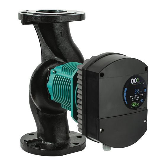
- Page 1 302-393 Installation & Operation Instructions Manual VR15, VR20, VR25 & VR30 (ALL CIRCULATORS ARE AVAILABLE IN LOW, MEDIUM AND HIGH HEAD MODELS) EFFECTIVE: August 2, 2021 SUPERSEDES: New Plant ID No. 001-5038 ECM High-Efficiency Circulators INSULATION SHELL INCLUDED...
-
Page 2: Table Of Contents
NOTE: This is an interactve manual. Clicking on a section below will take you directly to the page. Click on this icon to return to the Table of Contents TABLE OF CONTENTS 13. Controller Layout..............18 1. Symbols & conventions used in this document ...3 13.1 Connection considerations ...........19 1.1. -
Page 3: Symbols & Conventions Used In This Document
1. SYMBOLS & CONVENTIONS USED IN THIS DOCUMENT WARNING! Denotes that a failure to observe those instructions might cause damage to equipment or pose danger to the user. 1.1 ABBREVIATIONS AND CONVENTIONS USED IN THIS DOCUMENT Abbreviation Description Baud, Baud rate Serial communication speed, in bits per second including start, parity and stop bits. -
Page 4: Section 1 - Installation And Operation
TACO equipment voids the warranty. ATTENTION: L’ajout de liquides à base de pétrole ou de certains additifs chimiques à des systèmes utilisant un équipement TACO annule la garantie. CAUTION: Use supply wires suitable for 90°C. ATTENTION: Employer des fils d’alimentation adeqauts pour 90°C. -
Page 5: Pump Description
6. USE All Taco 00e VR pumps are intended for circulation of solid-free fluid in pressurized, hot and chilled hydronic systems. The self-sensing ECM pump constantly calculates pressure and flow, and adapts its speed to the appropriate flow. -
Page 6: Motor Rotation Procedure
Flange Bolt Sizes PUMP CLASS 120 ANSI FLANGE Model/Flange Size Bolt Hole Diameter Flange Thickness Bolt Hole Diameter Flange Thickness Min. Bolt Size Qty. VR15 (1-1/2”) 0.63 0.715 0.62 0.688 1/2” x 2-1/8” VR20 (2”) 0.75 0.76 0.75 0.75 5/8” x 2-3/16” VR25 (2-1/2”) 0.75 0.76... -
Page 7: After Installation Into Piping
8.1.2 After Installation into piping • Carefully open shutoff valves and check for leaks. • Make sure that the electrical box cover is mounted and that all cable glands are installed to prevent dust and particles from contaminating the electrical box. •... -
Page 8: Electrical Connections
Grounding is only meant for pump safety. System piping should be grounded separately. Wiring Instruction: The Taco VR Series is rated for use in single phase applications. It is essential wiring is completed by a qualified technician, in accordance with all local codes and regulations. Input voltage ranges as follows: •... -
Page 9: Setup And Operation
10. SETUP AND OPERATION: 10.1 Control Panel Layout 1. Bar Graph of Values ® 2. Numerical Display of Values series 3. Unit Display of the Currently Selected ECM HIGH-EFFICIENCY CIRCULATOR (Watts, Head Setting, Flow, or Speed) 4. Selected Mode (Automatic, Proportional Pressure, Constant Pressure, xRPM Constant Speed and Night Setback) 5. -
Page 10: Operation And Mode Selection
[ + ] Key Short press: • Scrolling through parameters upwards, not changing parameter values. • Scrolling • Changing Long press: • 3 seconds together with [ – ] key to enable night setback mode, • 5 seconds together with [ 3 ] and [ – ] keys to restore pump to factory default settings. 10.4 Operation and Mode Selection Once the desired mode is selected, the factory default parameter is displayed numerical display (except for activeADAPT®). -
Page 11: Restoring Factory Settings
10.6 Restoring Factory Settings To restore factory defaults, press and hold all three buttons for 5 seconds. The pump will be set to the acctiveADAPT® mode of operation. Any previously set values for pressure and RPM will be deleted. 10.7 Minimum Speed Adjustment 1. -
Page 12: Parallel Pumping
10.8 Parallel Pump Instructions 10.8.1Twin Pump Function: The VR Series Parallel Pump Function enables the communication between two pumps when piped in parallel, without the use of additional control devices. Parallel pump control requires both pumps connected via a CROSSOVER Ethernet cable. The installation of a check valve is required on the discharge side of each pump, installed at least 10 pipe diameters from the pump discharge. -
Page 13: Application
Setting Lag Pump IP Address via HTML page 2.2.1 Connect Laptop with standard Ethernet cable 2.2.2 Enter IP Address 192.168.0.245 in any Internet browser (you do not need to connect to the internet) 2.2.3 Once connected, navigate to the Network tab – make IP Address changes for Lag pump 2.2.4 CLICK SAVE 10.8.3 Confirm Pump to Pump Communication... -
Page 14: Specifications
11.2 Electrical Ratings: Model VR15L VR15M VR15H VR20L VR20M VR20H VR25L VR25M VR25H VR30L VR30M VR30H Input Voltage 110/240 110/240 200/240 110/240 110/240 200/240 200/240 200/240 200/240 200/240 200/240 200/240 All single phase, 47 To 63 Hz Max Power (HP) 0.37 0.65 0.91... -
Page 15: Standards, Protection And Flange Conn
11.3 Standards, Protection and Connection: • Insulation: Class H • Enclosure: Class 2, IP44 • Integrated Motor Protection (electronically protected) • Continuous Duty • UL778,1004-1,508C • CAN/CSA C22.2 #108, #100, #107.1 EMC(89/366EEC):EN61000 • LVD(73/23/EC):EN60335-1,EN60335-2-51 • Machine Safety(98/37/EC): EN ISO 12100 •... -
Page 16: Section 2. Controller (Vfd) Operation
Section 2. Controller (VFD) Operation 12. FEATURES This section describes the controller features for VR 15 through 30 L, M & H range of pumps. The controller is used for various remote control applications, including: • Remote on/off • Analog 0-10Vdc or PWM control •... -
Page 17: Bacnet Specifications • 12.2
BACNET SPECIFICATIONS • 12.2 Baud Rate 38400 (default) MAC Address 45 (default) Device Instance 12345 (default) Network IP 192.168.0.245 (default) 02:01:36:BF:42:AD (default) Gateway 192.168.0.1 MODBUS SPECIFICATIONS • 12.3 Data protocol Modbus Remote Terminal Unit (RTU) Modbus connector Screw-less terminals 2+1 pins. See section 16.3 “Connection to Modbus” Modbus connection type RS-485 Modbus wire configuration... -
Page 18: Analogue Signals
Analog Signals (SET1, SET2, SET3) • 12.5 Input Voltage Range -1 to 32 VDC When used as input. Output Voltage Range 0 to 12 V When used as output. 5 mA max. Load allowed per output. Input Resistance ~100 kW 0.5 mA load is added for most configurations. -
Page 19: Connection Considerations
13.1 Connection Considerations • All cables connected must be heat-resistant to at least +185 °F. • All cables connected must be installed in accordance with The National Electric Code / NFPA 79 / EN 60204-1. • All wires to the communications module must be connected to the terminals or cut. No loose wiring permitted. WARNING! •... -
Page 20: Control Modes And Priorities
RELAY AND ETHERNET CONNECTION NOTE: 7/8” max length Ethernet connector recommended. The Ethernet connection has a sharp cable bend angle and reducing the connection terminal length reduces this problem. NOTE: To maintain pump IP protection, the network cable should be pulled through the gland inlet and then crimped to a connector. -
Page 21: Control Variables
14.2 Control Variables Pump will respond to external controls according to selected pump operating mode. Consult proper pump operating manual for explanation. Symbol Regulation mode Module set point controls: activeADAPT® (RUN ONLY) Proportional pressure Maximum head Constant pressure Maximum head Constant speed Speed (RPM) Combined... -
Page 22: Module Mode Selection
14.3 Module Mode Selection WARNING! Before performing any work on the module, make sure that the pump and module electricity supply has been switched off and that it cannot be accidently switched on. There is a mode selection rotary switch in the terminal box. It can be rotated by gently inserting a screwdriver into the arrow mark on top and rotating the switch to desired value. -
Page 23: Mode 1
14.4 Mode 1 Digital switched enable / disable (run signal) and digital switched max or min speed. No external speed or head control Application: Using a digital switch to enable or disable the pump and a separate switch to force the pump to max or minimum speed (user selectable) Contact Position Function... - Page 24 MODE 1 – Digital switched enable / disable (on/off), external analogue 0-10Vdc speed or head control (pump starts on medium speed or head) Application: Using an external 0-10Vdc signal to control the speed (or head) of the pump and a separate signal to enable/disable the motor.
- Page 25 Sequence of Operation: • Set 3 and Set 1 Open – Pump in Standby (VFD powered, motor is off, no flow), regardless of 0-10Vdc signal • Set 3 and Set 1 Closed – increasing 0-10Vdc signal - 0 to 2 V pump runs at medium speed (pre-purge) - 2 to 3 V pump runs at min speed (25% of max speed) or min head (15% of max head) NOTE: Min speed user adjustable to meet min flow requirements - 3 to 10 V speed increases linearly to V...
- Page 26 Figure 1: External 2..10 V transfer curve for Mode 1 0..10 V (RUN+MAX) Figure 2: External 0..10 V transfer curve for Mode 1 Sequence of Operation: • Increase of 0-10Vdc signal - 0 to 2 V pump off - 2 to 3 V pump runs at min speed (25% of max speed) or min head (15% of max head) NOTE: Min speed user adjustable to meet min flow requirements - 3 to 10 V speed increases linearly to V •...
-
Page 27: Mode 2
14.5 MODE 2 – Digital switched enable / disable, external analogue 0-10Vdc speed or head control Application: Using an external 0-10Vdc signal to control the speed or head of the pump and a separate signal to enable/disable the motor. Pump starts on low speed or head. Sequence of Operation: •... -
Page 28: Mode 3 & 4
14.6 MODE 3 & 4 – PWM (Pulse Width Modulation) External Speed or Head Control Modes 3 & 4 are used for PWM control and feedback according to IEC 60469-1. Mode 3 stops the pump when the signal is 0% or missing, Mode 4 runs the pump at fill power. Application: Using an external PWM signal to control the speed or head of the pump. - Page 29 MODE 3 – PWM Solar Sequence of Operation: • Set 3 and Set 1 Open – Pump in Standby (VFD powered, motor is off, no flow), regardless of PWM signal • Set 3 and Set 1 Closed – increasing PWM signal - 0 to 12% pump standby - 12% to 15% pump runs at min speed (20% of max speed) or min head (10% of max head) NOTE: Min speed user adjustable to meet min flow requirements at 3 V)
- Page 30 MODE 4 – PWM Heating Sequence of Operation: • Set 3 and Set 1 Open – Pump in Standby (VFD powered, motor is off, no flow), regardless of PWM signal • Set 3 and Set 1 Closed – increasing PWM signal - 0 to 5% pump at max speed or head - 5 to 85% speed decreased linearly with % change - 85% to 93% pump on standby...
-
Page 31: Relay Output
15. RELAY OUTPUT Terminal Designation Terminal description MODE Mode selection rotary switch. Used to show and configure mode of operation for relay. LED1 / LINK Slowly blinking when module is powered, permanently lid when link established Flashing yellow when data reception detected. Combined (OR) LED2 / ACT with Modbus &... -
Page 32: Bus Topology
16.1 Bus Topology Figure 5: connecting to a network via router Figure 4: connecting to a computer with a standard cable 16.2 Connection to a Pump Ad-Hoc When connecting directly with the computer, a standard Ethernet cable must be used to connect with the pump. - Page 33 Instructions for connection: 1. Connect the pump via laptop a. Connect the pump and laptop using a standard or crossover Ethernet cable b. Observe the RJ45 communication LED’s with both the pump and laptop powered i. LED1 / LINK: Slowly flashing when powered, solid when link established ii.
- Page 34 Examples: Overview Tab: Indicates how the pump is operating in real time values. Note: no adjustments can be made from this page. Operation Data: Real time operational data and maximum values Example: Power is 4 Watts (pump is in standby) – and has a maximum wattage of 1550W, shown in brackets. Control Signals: Mode switch setting and all external control input settings and actual values.
- Page 35 Pump Configuration: Using the drop down the pump settings can be changed Op Mode: Changes to Operational Modes can be made using the dropdown (Off, Proportional & Constant Pressure, Constant Speed or Combined Mode) Max Head: Dropdown selects a specific maximum head (not applicable in Constant Speed Configuration). This value is carried over to the max value in brackets on the Overview Tab Max RPM: Dropdown sets the maximum speed.
- Page 36 Set 1, 2 and 3: Depending on Mode Switch setting various drop-down selections are available Relay Function: Ability to change the event that changes the relay position (Pump Fault, Pump Ready, Pump Operation, Always on and No Function). Pump Fault is factory default. Save All: IMPORTANT: Any changes made in this tab require the SAVE button be clicked for the changes to take effect.
- Page 37 MORE: Update Firmware: For uploading updates to the software or firmware Summary Notes: • For the best troubleshooting experience (product or application) ensure screenshots are taken of at least the Overview and Pump pages • Always click “Save” when changing settings (Pump and Network) •...
- Page 38 1. Overview (default page when you connect to the pump, web page OVERVIEW) displays pump operation summary i.e.: • Operating mode • Power consumption • Head • Estimated flow • RPM • Estimated efficiency • Priority set point • Mode switch position •...
-
Page 39: Bacnet
17. BACnet 17.1 BACnet MS/TP communication is standard with all VR models VR Series module enables BACnet MS/TP communication with all models. BACnet Standardized Device Profile (Annex L): BACnet Operator Workstation (B-OWS) BACnet Advanced Operator Workstation (B-AWS) BACnet Operator Display (B-OD) BACnet Building Controller (B-BC) BACnet Advanced Application Controller (B-AAC) BACnet Application Specific Controller (B-ASC) -
Page 40: Device Address Binding
17.3 Device Address Binding Is static device binding supported? (This is currently necessary for two-way communication with MS/TP lag pumps and certain other devices.) 17.4 Networking Options None 17.5 Network Security Options Non-secure Device - is capable of operating without BACnet Network Security 17.6 Character Sets Supported ISO 10646 (UTF-8) IBM™/Microsoft™... -
Page 41: Analog Inputs
17.8 Analog Inputs (Object Type 0) • NOTE: Values are read-only Instance Object Name Unit Description Currently active Setpoint - 100% represents maximum AI.0 Actual Set Point - Pump performance depending on Control Mode - <0% indicates user control Current pump operating mode AI.1 Actual Operating Mode - Mirrors AO.1 when remotely controlled... -
Page 42: Binary Inputs
17.10 Binary Inputs (Object Type 3) • NOTE: Values are read-only Instance Object Name Unit Description BI.0 Remote Access Active Indicates remote control 0 = Local 1 = Remote (Bus control). BI.1 Near Minimum Speed Indicates if the pump is running near minimum speed. 0 = No 1 = Yes. -
Page 43: Modbus
18. MODBUS 18.1 Modbus Related Interface Terminal Designation Terminal Description MODE Can be used to reset network configuration. LED2 / ACT Indicates Ethernet activity or Modbus reception. B/D- RS-485 negative data signal for Modbus. A/D+ RS-485 positive data signal for Modbus. COM/0V RS-485 common and analog input common (ground). -
Page 44: Connection To Modbus
18.3 Connection to Modbus Connection to RS-485 A screened, twisted-pair cable should be used. The cable screen must be connected to the COM terminal and connected to safety ground at one point. NOTE: In some cases, better performance is achieved if no COM connection is made. Device can operate with 2 wire connection. Speed, parity and address Modbus RTU By default, each device is set to 19200-E-1 (even parity), address 245. - Page 45 Register overview VR Series Modbus RTU registers are grouped in the following register blocks: Start Address Register block Readable/Writeable Description VR Series configuration Configuration of the VR module. VR Series status Status registers for the VR module. Pump control Pump control registers. Pump status Status data from the pump.
- Page 46 Address Register name Range Resolution Description Delay in milliseconds for lag reply. This delay will be Lag Delay 0..10000 1 ms added to every Modbus reply [default = 0]. RESERVED ModbusAddress 1..247 Modbus lag/device address [default = 245]. RS-485 transmission speed enumeration. 0 = 1200 baud 1 = 2400 baud 2 = 4800 baud...
- Page 47 Address Register name Range Resolution Description Configuration for SET1 terminal. 0 = “NO FUNCTION” 1 = “RUN input 2-3V” 2 = “MAX input 0-10V” 3 = “MAX input 2-10V” 4 = “RUN input 4-6mA” 5 = “MAX input 0-20mA” 6 = “MAX input 4-20mA” 7 = “FB output 10.5V”...
- Page 48 Pump control registers Registers in this block are read with either function codes 0x03 or 0x04. They can be written as holding registers with function codes 0x06 and 0x10. Address Register name Range Description Control bit that sets local or remote control. Setting this bit will enable pump control over Modbus.
- Page 49 Pump status registers Registers in this block can be read by means of function codes 0x03 and/or 0x04. They are read-only. Address Register name Description StatusReg b0..b5: RESERVED Indicates if the pump is rotating (running) or not. b6: Rotation 0 = No rotation 1 = Rotation.
- Page 50 Pump data registers Registers in this block can be read by means of function codes 0x03 and/or 0x04. They are read-only. Address Register name Range Resolution Description Head 0.01 m Pump head estimation in meters of water column. Flow 0.1 m Pump flow estimation.
-
Page 51: Fault Finding
19. FAULT FINDING 19.1 Error Codes The following error codes will be displayed on the user interface, HTML Pump Overview tab (Status) for current error, HTML Log tab for error history and the appropriate Modbus and BACnet registers. Error categories E1x Motor Load Errors E2x Overload Protection Errors E3x Pump Errors... - Page 52 Error Codes Continued Error Fault Description Cause Pump Reaction / Solution Faulty LED LED on the User Interface failure Pump runs normally, but no display Check ribbon able connection between the board and drive cover. If OK, replace the drive cover Communications Loose contact Pump runs normally.
-
Page 53: Performance Curves
Performance Curves VR15 & VR20 ECM High-Efficiency Circulators VR Circulators are available in High (H), Medium (M) and Low (L) Head Models VR15 Performance Curves FLOW (liter/min) 18.3 VR15H 13.7 VR15M VR15L FLOW (GPM) VR20 Performance Curves FLOW (liter/min) 18.3 13.7 VR20H VR20M... - Page 54 Performance Curves VR25 & VR30 ECM High-Efficiency Circulators VR Circulators are available in High (H), Medium (M) and Low (L) Head Models VR25 Performance Curves FLOW (liter/min) 1135 21.3 VR25H 52.5 10.7 VR25M VR25L 17.5 FLOW (GPM) VR30 Performance Curves FLOW (liter/min) 1135 1514...
-
Page 55: Hydronic Institute Energy Ratings
VR15 (L / M / H) VR20 (L / M / H) -55-... -
Page 56: Limited Warranty Statement
(6) months from date of shipment (1) year from the date of start-up or one (1) year suitable for use with a Taco product or part, or for If in doubt as to whether a particular substance is (whichever occurs first).