
Related Manuals for ACCO Brands SEAL 62 Base


Summary of Contents for ACCO Brands SEAL 62 Base
- Page 1 62/54Base Mounter and Laminator User Manual “A” Version Models, Rev B October 2017...
- Page 2 SEAL® shall not be liable for incidental or consequential damages in connection with, or arising out of the furnishing, performance, or use of this document and the program material which it describes. 2017 ACCO Brands USA...
- Page 3 INTRODUCTION Thank you for purchasing your SEAL® 62/54 Base. Maximum effort has been invested in the design of this machine to give you years of reliable service. As you become familiar with your machine you will appreciate the high quality of its output and the excellence in engineering stated in its smartly styled design.
-
Page 4: Table Of Contents
TABLE OF CONTENTS Warranty and Safety instructions Warranty 1.1.1 Warranty conditions 1.1.2 Warranty period End of Life (EOL) Statement Safety 1.3.1 Safety features 1.3.2 Safety instructions Warnings 1.4.1 General ESD-warning 1.4.2 In this manual 1.4.3 On the machine Description 1.1. General description Parts identification Process principle... - Page 5 Operating Process controls 5.1.1 Control panel 5.1.2 Additional controls Operating modes 5.2.1 Normal mode 5.2.2 Slow mode Placing film rolls 5.3.1 Auto-grip shafts 5.3.2 Loading shaft with film rolls Webbing 5.4.1 Release liner and splitter bars 5.4.2 Using the upper section only 5.4.3 Upper and lower section 5.4.4...
-
Page 6: Warranty And Safety Instructions
Warranty and Safety instructions Warranty The warranty period and conditions stated in this chapter are merely a summary of the general SEAL® warranty conditions. For the exact details on the warranty period and conditions for your machine, please contact your dealer. -
Page 7: Safety
Safety This machine is provided with safety equipment to promote safe machine operation. The manufacturer has done everything possible to prevent any possible danger and to inform you as accurately and comprehensively as possible of any hazards relating to the operation of the machine. -
Page 8: Safety Instructions
1.3.2 Safety instructions Work safely! The owner of the machine is responsible for safe operation of the machine. He therefore is obliged to familiarize operating personnel with the contents of this manual and make them aware of all possible hazards. Do not change, remove or disable the safety facilities. -
Page 9: On The Machine
1.4.3 On the machine On the machine (See Figure 1) you will find the following warning symbols in black on a yellow background. ROTATING PARTS (3) DANGER OF GETTING INJURED BY ROTATING PARTS. MAKE SURE THAT THESE ROTATING PARTS DO NOT CATCH YOUR FINGERS, CLOTHING, HAIR, ETC. -
Page 10: General Description
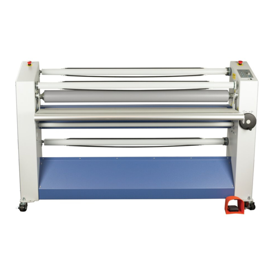
This chapter describes the machine and its operating basics. 1.1. General description The machine described in this manual is a mono-directional machine dedicated for processing pressure sensitive materials. While feeding through images and the coating films, the two silicone coated main rollers generate the pressure. -
Page 11: Process Principle
Process principle In all processes the materials are fed through the nip from the front side to be joined together by pressure. A process that makes maximum use of the machine is shown in Figure 3. Shown is a double sided laminating (decalling) process. -
Page 12: Specifications
Specifications Identification The machine identification label (example in Figure 4) is located at the bottom of the right-hand cabinet, on the rear side of the machine. This label indicates the model (version) and the rated power of the machine. CAUTION: THE POWER SUPPLY MUST BE ABLE TO PROVIDE THE RATED POWER ACCORDING TO THE ELECTRICAL CODE REQUIREMENTS FOR THE AREA OF INSTALLATION. -
Page 13: Material Specifications
Material specifications Maximum width: Metric American Process up to 40°C (104 °F) – 62 Base 1600 - 54 Base 1400 55.1 Maximum roll diameter: (same both models) Material unwind (upper unwind) Material unwind (bottom unwind) Release liner wind-up Maximum panel thickness: Roll core inside diameter: 76.2 Machine specifications... -
Page 14: Installation
Installation WARNING: INSTALLATION MUST BE CARRIED OUT BY SKILLED PERSONNEL. Unpacking At delivery, the machine is packed in a plastic bag to avoid moisture penetration. It is transported in a carton box and is fastened onto a wooden pallet. Place the pallet in a space where there is enough room to roll the machine off from the pallet (approx. 6 m). -
Page 15: Installation
Installation Note: Make sure that the machine, in its final location, has adequate space. You will need room to feed, receive and trim images. See Figure 6. L = Maximum board length, S = Minimum space 60 cm.(24”). Figure 6: Working space. Move the machine (and the accessories) to its final location. -
Page 16: Transport
CAUTION: Check the mains values before connecting. See section 2.4 for power supply details. Only if absolutely necessary, use an extension cable of ample capacity. Unroll the extension cable completely. Connect the machine to the mains using the power cable supplied with the machine. Minimum recommended service, standard 50Hz or 60Hz, single phase 230VAC 13A with breaker not exceeding 16A or single phase 115VAC 20A with a breaker not exceeding 20A. -
Page 17: Operating
Operating This chapter describes the function of the controls and indicators, the operating modes, how to set up and operate the machine and a number of applications. The sections in this chapter are placed in a sequence in which the information is needed for laminating processes. For the mounting process the sections 4.3 and 4.4 can be skipped with the exception of setting the pressure (see section 4.4.5). - Page 18 Pressure indication (2), 4 LED’s; The LED’s indicate the pressure setting of the main rollers. When 2 LED’s light at the same time, they indicate the tens in between. See specifications for actual pressure range. All four LED’s flashing indicates a pressure or nip setting error. The LED’s start flashing at 10% overload.
-
Page 19: Additional Controls
4.1.2 Additional controls Figure 9: Additional controls Emergency stop buttons (1), push and hold button; When pressed the rotation of the rolls is stopped immediately and the button is locked into this stop position. The safety indicator LED will flash while the button is depressed. Turn the button to unlock it. -
Page 20: Operating Modes
Operating modes The machine is either in normal mode, or slow mode. 4.2.1 Normal mode When slow mode is not activated (normal mode), the rotation speed of the rollers is set via the speed control knob. Start rotation by pressing the forward button or the footswitch. Rotation stops when a stop button is pressed or the footswitch is released. -
Page 21: Slow Mode
4.2.2 Slow mode Enter or leave Slow mode by pressing the slow mode button for 1 second. The selection is indicated by the slow mode indication LED. Entering slow mode will not change anything to the current movement of the rollers. In slow mode the rollers can run at normal or at slow mode speed. -
Page 22: Auto-Grip Shafts
4.3.1 Auto-grip shafts Both shafts in the rear of the machine are the same. Your machine may have the plastic Auto-grip shafts which look different than the figure below but function the same. The shafts fit into the machine in both ways. On the control panel side of the machine all the shafts and the supports snap together. -
Page 23: Loading Shaft With Film Rolls
4.3.2 Loading shaft with film rolls The film roll is put on the shaft depending on the type of film and the use in the upper or lower section of the machine. In general pressure sensitive film with release liner (A) is rolled up with the liner (3) and adhesive (2) to the outside of the film (1), whereas film without release liner (C) has its adhesive layer to the inside of the roll. -
Page 24: Webbing
Webbing For laminating processes the machine must be webbed before images on thin film or on panels can be processed. The machine can be webbed for single sided or double sided processing. When mounting images the machine is not webbed. Note: In single sided processes adhesive residues will stay behind on the bottom roller where the film is wider than the images. -
Page 25: Using The Upper Section Only
4.4.2 Using the upper section only Figure 15: Webbing upper section. Remove the image guide. Unwind the film from the upper or top unwind roll. Feed a film without release liner over the splitter bar (A). Feed a film with release liner underneath the splitter bar (B). Pull the film forward until approximately 10 cm (4 in.) is on the in-feed table. -
Page 26: Presetting The Tension
Pull the film forward until it almost reaches the in-feed table and apply it to the upper roller. If the film has a release liner (B): Peel off the release liner, Pull it up and stick it from below onto the tube on the wind-up position. 4.4.3.2 Now web the lower section Figure 17: Webbing lower section. -
Page 27: Pressure Setting
4.4.5 Pressure setting 4.4.5.1 Thin images When processing thin images (printer output, posters, etc.) pressure is preset when the upper and lower material is webbed. When the leader panel or release board is through the nip, the nip is set to zero and pressure is preset. -
Page 28: Processes And Settings
Processes and settings 4.5.1 Mounting images or decals In this process the machine is not webbed with film. When mounting images onto a (pre-coated) board (B), the adhesive is on the mounting side of the board. When mounting decals (A), the adhesive is on the back of the image. -
Page 29: Pre-Coating Panels
4.5.2 Pre-coating panels This process is used to coat boards (substrates) with a pressure sensitive mounting film onto which images can be mounted. This process can also be used to create a carrier board. In this case a film with a non-stick surface is used. Note: The mounting film is usually provided with one release liner. -
Page 30: Decaling
Using release liner Use a roll of release liner in the lower section. Web the upper and lower section of the machine as described above (section 4.4.3). When the images are cut from the result, the release liner will separate from the image automatically. -
Page 31: Maintenance
Maintenance Cleaning The machine has to be cleaned regularly. Dirt and dust will have a negative influence on the result of the lamination processes. CAUTION: Do not use abrasive materials for cleaning the machine. This can damage the painted surfaces or the silicone covering of the rollers. Use a damp cloth for cleaning. -
Page 32: Preventive Maintenance
Preventive maintenance Our machines are designed in such way that they need little (preventive) maintenance in addition to the cleaning. The following checks have to be performed: Auto-grip shafts with blocking cords. 5.2.1 Auto-grip shafts Check the auto-grip mechanism on each shaft. ... -
Page 33: Technical Assistance
5.3.1.2 Pressure too low. Figure 21: Wrinkles due to low pressure. Increase the roller pressure a little (5-10%). 5.3.1.3 Unwind tension too low. Figure 22: Wrinkles due to low unwind tension. Increase the unwind tension until the wrinkles (6) in the film on the roller disappear. The lines (7) in the process result will disappear as well. -
Page 34: Process Control Sheet
Process Control Sheet Note: We recommend that you make a photocopy of this page. With each successfully run application, record the process and settings and a diagram of the webbing procedure. Keep the record so the application can be repeated at a later date. Hint: If a standard image is made available for each new process then sales materials and samples can be developed for reference. -
Page 35: Glossary
Glossary Carrier board or sled A board with a non-stick surface that is used to support the image when laminating one side of an image only. Decal An image with an adhesive backside (Am.: Sticker). Decaling Providing an image with laminate on the image side and adhesive on the backside. Encapsulating Sandwiching an image between two heat sensitive films. - Page 37 Glossary...
- Page 38 Contact Us: SEAL Brands Technical Service – US & Canada 1-800-486-6502 Fax: 1-800-966-4554 Email: [email protected] SEAL Brands Customer Service – US & Canada 1-800-257-7325 Fax: 1-800-966-4554 Email: [email protected] www.sealgraphics.com...