Table of Contents
Representative models:
FV -0511V KSL 2
FV -1115V KL 2
READ AND SAVE THESE INSTRUCTIONS
Thank you for purchasing this Panasonic product.
Please read these instructions carefully before attempting to install, operate or service
the Panasonic product. Please carefully read the "GENERAL SAFETY INFORMATION"
Failure to comply with instructions could result in personal injury or property damage.
Please explain to users how to operate and maintain the product after installation,
and this booklet should be presented to users.
Please retain this booklet for future reference.
INSTALLATION INSTRUCTIONS
FV -0511V KL 2
Model No.
Contents
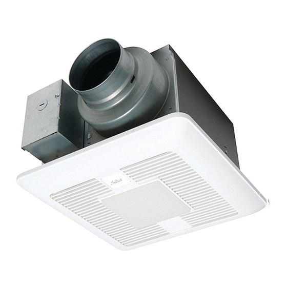
Ventilating Fan
BACK COVER
BACK COVER
BACK COVER
2-3
3-4
4
5
5
5
5
6
6-7
7
8
8-10
10
11
Table of Contents

Related Manuals for Panasonic FV-0511VKL2


Summary of Contents for Panasonic FV-0511VKL2
-
Page 1: Table Of Contents
Thank you for purchasing this Panasonic product. Please read these instructions carefully before attempting to install, operate or service the Panasonic product. Please carefully read the “GENERAL SAFETY INFORMATION” Failure to comply with instructions could result in personal injury or property damage. -
Page 2: General Safety Information
GENERAL SAFETY INFORMATION For Your Safety To reduce the risk of injury, loss of life, electric shock, fire, malfunction, and damage to equipment or property, always observe the following safety precautions. Explanation of symbol word panels The following symbol word panels are used to classify and describe the level of hazard, injury, and property damage caused when the denotation is disregarded and improper use is performed. -
Page 3: Please Read Prior To Installing This Fan
GENERAL SAFETY INFORMATION CONTINUED Do not disassemble the unit for reconstruction. It may cause fire or electric shock. A statement to the effect that when the product is to no longer be used, it must not be left in place but remove, to prevent it from possibly failing. Ceiling joist must be subjected to static load more than five times the weight of the product. -
Page 4: Description
Multi-Speed module, these models increase to a maximum level of 150 CFM for the FV-1115VKL2 and 110 CFM for the FV-0511VKSL2 and FV-0511VKL2 either when the switch is turned on or activated by the optional Condensation Sensor module or the optional Motion Sensor module. -
Page 5: Unpacking
-ST4.2X20) DIMENSIONS 1 1/2 (37) Unit: inches (mm) 1 1/4 (30) 4 1/2 (114) 6 5/8 (169) 7 1/2 (190) FV-1115VKL2 FV-0511VKSL2 FV-0511VKL2 13 (330) Part name Part name FV-1115VKL2 Connector cover Blade Grille Base PCB box Junction box Pick-A-Flow switch... -
Page 6: Feature
The Pick-A-Flow switch on the face of all WhisperGreen Select fans allows the option to choose 50 – 80 – 110 CFM for the FV-0511VKL2, FV-0511VKSL2 or 110 – 130 – 150 CFM for the FV-1115VKL2. These fans can run continuously or intermittently, depending upon the needs of the owner. -
Page 7: Motion (Plug 'N Play Function Devices)
INDICATION (PLUG ‘N PLAY FUNCTION DEVICES) CONTINUED Humidity selector range from aroun 30% to 80%. Factory setting is around 50%. Timer preset selector positions Timer [min] Factory setting : 20 minutes. Position ” ” : For factory use 1. The product will run when environment humidity rise rapidly but not reach to the humidity setting, and stop after delay preset time. -
Page 8: Installation (Plug 'N Play Function Devices)
INSTALLATION (PLUG ‘N PLAY FUNCTION DEVICES) You can purchase the specified Plug ‘N Play devices that are explained on page 6-7 and install them in positions . Position can only be used with Multi-Speed module (model FV-0511VKSL2 already have this control installed), position can be used for any of the other optional control modules. - Page 9 INSTALLATION (NEW CONSTRUCTION) CONTINUED 7. Refer to wiring diagram on page 5. W H I TE Conduit BLA CK Follow all the local electrical safety codes as well as the National Electrical Junction B L UE GREEN Earth ground Code (NEC). Using UL approved wire Wire nuts nuts, connect house power wires to Live...
-
Page 10: Installation (Retrofit)
INSTALLATION (NEW CONSTRUCTION) CONTINUED 11. Adjust Pick-A-Flow switch.(Refer to indication on FEATURE.) Ceiling Mounting spring 12. Insert the other mounting spring into the slot as Gloves shown and mount grille to fan body. (Fig.10) Grille Fig.10 CAUTION Mount grille carefully so that lead wire is not pinched. -
Page 11: Maintenance (Cleaning)
MAINTENANCE (CLEANING) WARNING Mounting spring Disconnect power source before working on unit. Grille Slot Gloves Fig.14 CAUTION Ceiling Routine maintenance must be done every year. Please wear gloves during the cleaning work. Clasp Never use gasoline, benzene, thinner or any other such chemicals for cleaning the ventilating fan. -
Page 12: Practical Guide To Installation
Warning Concerning Removal of Covers. The unit should be serviced by qualified technicians only. Your product is designed and manufactured to ensure a minimum of maintenance. Should your unit require service or parts, call Panasonic Call Center at 1-866-292-7299 (USA) or 1-800-669-5165 (Canada). Panasonic Corporation of North America Panasonic Canada lnc.