Table of Contents
Table of Contents

Related Manuals for YASKAWA MA2010


Summary of Contents for YASKAWA MA2010
- Page 1 YR-MA02010-A10 Operating and maintenance instructions MA2010...
- Page 2 This documentation – also in part – may be reproduced or made available to third parties only with the express approval of YASKAWA Europe "Robotics Division GmbH". We have checked the content of this publication for compliance with the hardware described.
-
Page 3: Table Of Contents
Table of contents Table of contents General..............5 Notes for safe operation . - Page 4 Table of contents Internal cables and compressed air lines........40 Maintenance and inspection .
-
Page 5: General
Indicates important background information and application advice. Frequently used terms The YASKAWA robot is a product of YASKAWA Electric Corporation, and is provided by default with the robot controller, the programming pendant and robot cable. The terms are designated as follows in this manual:... -
Page 6: Target Group
For optimal use of our products, we recommend our customers to take part in a training session at the YASKAWA Academy. For information on the training programme, please visit www.yaskawa.eu.com or contact our branch offices directly. -
Page 7: About This Manual
If your copy of the operating and maintenance instructions is damaged or lost, please contact the local YASKAWA branch office to order a new copy. The official branch offices are listed on the last page. Please mention the manual number in your order. -
Page 8: Safety
General Safety START HOLD REMOTE TEACH PLAY EDIT DISPLAY UTILITY JOB CONTENT TEST01 S:0000 CONTROL GROUP:R1 TOOL: 0000 0001 SET B000 1 0002 SET B001 0 0003 MOVJ VJ=80.00 0004 MOVJ VJ=80.00 0005 DOUT OT#(10) ON 0006 TIMER T=3.00 0007 MOVJ VJ=80.00 0008 MOVJ VJ=100.00... - Page 9 General WARNING! Death or injury because of danger of crushing Before you release the emergency stop button (see Fig. 1-4: "Release of emergency stop button by turning") note the following: Make sure that there is no one within the maximum working range of the robot. ...
-
Page 10: Manufacturer
General Manufacturer Address: YASKAWA ELECTRIC CORPORATION 2-1 KUROSAKISHIROISHI YAHATANISHI-KU KITAKYUSHU JAPAN Authorized representative Address: YASKAWA Europe GmbH Robotics Division Yaskawastr. 1 85391 Allershausen Germany... -
Page 11: Supply
Supply Supply Checking the scope of delivery The standard delivery includes the following items: Fig. 2-1: Scope of supply Programming pendant The present assembly instructions Robot controller Cable Robot... -
Page 12: Position Type Plate
2-1 SHIROISHI KUROSAKI, YAHATANISHILU KITAKYUSYU, JAPAN YASKAWA Europe „Robotics Division“ GmbH Yaskawastr. 1, D-85391 Allershausen Fig. 2-2: Position type plate NOTICE Please contact the local YASKAWA branch office if the serial numbers do not match the information on the delivery note. -
Page 13: Transportation
Transportation Transportation CAUTION! Personal injury or damage to property The system consists of precision components. If this precaution is not taken, performance may be impaired. A crane or forklift may only be operated by authorised personnel. The same applies to the use of slings. -
Page 14: Using A Crane
Transportation 3.1.1 Using a crane Adequate load handling devices must be used to transport the robot. Make sure that the robot is lifted as shown in the diagram "Transport by crane". Fig. 3-1: Transport with crane Shipping bracket and bolts 2 screws M12 x 30 View A... -
Page 15: Using A Forklift
Transportation 3.1.2 Using a forklift If the robot is transported using a forklift, it should be fixed on a pallet with transport securing devices and shipping bolts as shown in the figure below "Transport using a forklift". Make sure that the forklift and the transportation route have sufficient bearing capacity. Always take due care when transporting the robot. -
Page 16: Shipping Brackets And Bolts
Transportation Shipping brackets and bolts The robot is equipped with transport securing devices and shipping bolts to reduce external forces to a minimum during transport. • The shipping brackets and bolts are painted yellow. • The shipping bracket will be fastened by 2 screws M12. Fig. -
Page 17: Installation
Installation Installation CAUTION! Personal injury and damage to property The following precautions must be taken. Check that the robot controller is complete and not damaged. Do not put into operation a robot controller that is damaged or incomplete. ... -
Page 18: Location
Installation Location When installing a robot, it is necessary to satisfy the undermentioned environmental conditions: • Ambient temperature: from 0° C to + 45° C. • Air humidity: 20% to 80% relative humidity (non-condensing). • No corrosive gases, liquids or explosive gases. No water, oil, dust and free from excessive electrical noise (plasma). - Page 19 Installation 200±0.1 260±0.1 Fig. 4-1: Mounting the robot on the base plate Screws at least 25 mm Spring washer Anchor bolt (M16 or greater) Washer 2 holes Ø 12 Robot base 4 holes Ø 18 Base plate adhesive...
- Page 20 Installation Fig. 4-2: Base plate Horizontal direction Vertical direction Force F Moment M Force F Moment M Emergency stop 8820 N 6370 Nm 10290 N 13720 Nm Acceleration 2940 N 1915 Nm 3430 N 5145 Nm Deceleration Tab. 4-1: Forces and moments of the robot Fig.
- Page 21 • Fixing the robot base NOTICE For suspended mounting in any position, please contact the local YASKAWA branch office. S-axis working range For the wall-mounted type, the S-axis movable range is ±30° (the range is adjusted prior to the shipment).
-
Page 22: Wiring
Wiring Wiring DANGER! Danger to life due to electric shock, risk of fire due to short circuit. Wiring must be performed by authorized or certified personnel. Follow the instructions given below before wiring. Make sure that the earthing resistance does not exceed 0.1 Ω. ... -
Page 23: Cable Connections
Robot Serial No. YASKAWA ELECTRIC CORPORATION 2-1 SHIROISHI KUROSAKI, YAHATANISHILU KITAKYUSYU, JAPAN YASKAWA Europe „Robotics Division“ GmbH Yaskawastr. 1, D-85391 Allershausen Fig. 5-2: Connecting the robot system Two cables are delivered with the robot (refer to Fig. 5-3: "Robot cable"). -
Page 24: Connecting The Robot
Wiring 5.2.1 Connecting the robot 1. Check the encoder cable (1BC) and the power cable (2BC). 2. Connect the encoder cable (1BC) to the connector plate of the robot. 3. Connect the power cable(2BC) to the connector plate of the robot. Make sure that you hear each locking clip snap into place (clicking sound). -
Page 25: Connecting The Robot Control
Wiring 5.2.2 Connecting the robot control Attach the robot cables in the following order. 1. Connect the encoder cable (1BC) X11 connection X-1 to the robot controller. 2. Connect the power cable (2BC) X21 connection X-2 to the robot controller. Make sure that you hear the locking clips snap into place (clicking sound). -
Page 26: Connecting The Programming Pendant
Do not open the door Date/Signature with power ON. Type ERDR- Robot Type Robot Order No. Robot Serial No. YASKAWA Electric corporation 2-1 Kurosaki Shiroishi Yahatanishi-Ku Kitakyushu-City Fukuoka 806-0004 Japan Kammerfeldstr. 1, D-85391 Allershausen NJ3053-1 CHECK ALL THE DOOR LOCKS PROPERLY. NJ3005-1 PROGRAMMING PENDANT Fig. -
Page 27: Technical Data
Technical data Technical data Type: Celling mounted Types of Mounting: Degree of freedom: 10 kg Carrying capacity: ± 0.08 mm Repeatability: Power consumption: 2.0 kVA 280 kg Weight: Working area main axis: S-axis (turning) -180° ~ +180° L-axis (lower arm) -105°... -
Page 28: Parts And Work Axis Label
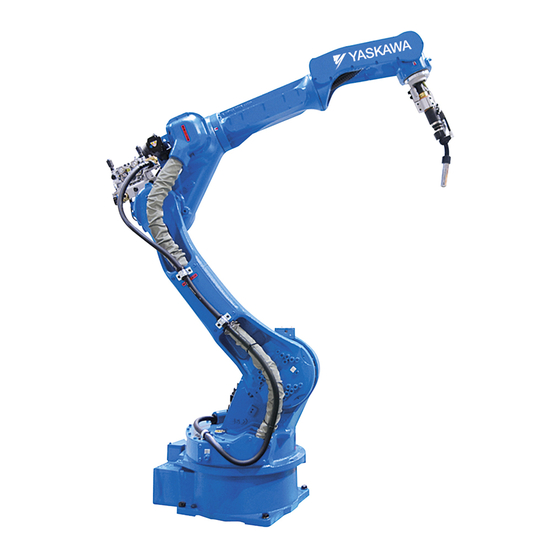
Technical data Parts and work axis label Fig. 6-1: Part names and working axes Upper arm (U-arm) Rotating head of S-axis Wrist Flange Robot base Lower arm (L-arm) Robot base dimension Fig. 6-2: Robot base dimensions 4 mounting holes Ø 18 Hole Ø... -
Page 29: Dimensions And Defined Working Area
Technical data Dimensions and defined working area 1284 229 266 1082 2365 Fig. 6-3: Part names and working axes P point The working area in which the robot can work with its wrist units (B-axis) pointing downwards. Working area, defined All dimensions in mm with point P... -
Page 30: Adjustable Working Area
Technical data Adjustable working area Depending on the type of use, the S-axis working area can be changed. If any modification is necessary, please contact the local YASKAWA branch office. Item Specifications S-axis working range ± 180° (standard) ± 150°... - Page 31 Technical data 100% Fig. 6-4: Stop position of the robot axes Definitions Description Category 0 Load 100% pink Category 0 Load 66% green Category 0 Load 33% gray Category 1 blue Overrun distance degrees° [deg] Overrun time second [sec] Robot speed degrees°/second [deg/s]...
-
Page 32: Stop Category 0
Technical data 6.5.1 Stop category 0 6.5.1.1 Stop position S-axis 100% [deg/s] [deg/s] Fig. 6-5: Stop position 100% [deg/s] [deg/s] Fig. 6-6: Stop position 66% [deg/s] [deg/s] Fig. 6-7: Stop position 33%... - Page 33 Technical data 6.5.1.2 Stop position L-axis 100% [deg/s] [deg/s] Fig. 6-8: Stop position 100% [deg/s] [deg/s] Fig. 6-9: Stop position 66% [deg/s] [deg/s] Fig. 6-10: Stop position 33%...
- Page 34 Technical data 6.5.1.3 Stop position U-axis 100% [deg/s] [deg/s] Fig. 6-11: Stop position 100% [deg/s] [deg/s] Fig. 6-12: Stop position 66% [deg/s] [deg/s] Fig. 6-13: Stop position 33%...
-
Page 35: Stop Category 1
Technical data 6.5.2 Stop category 1 The stopping angle and time at the emergency stop in category 1 are not subjected to the robot position and the load. Stop of category1 doesn't depend on the robot position and the load. 6.5.2.4 Stop position S-axis [deg/s]... - Page 36 Technical data 6.5.2.6 Stop position U-axis [deg/s] [deg/s] Fig. 6-16: Stop position...
-
Page 37: Allowable Load For Wrist Axis And Wrist Flange
Allowable load for wrist axis and wrist flange Allowable load for wrist axis and wrist flange Wrist flange The dimensions of the wrist flange are shown in the following figure "Wrist flange". To ensure that the zero position marks can be seen at all times, the tool may only be flange- mounted with the inner diameter. -
Page 38: Allowable Wrist Load
(see the following figure and table). For further information or assistance, please contact your YASKAWA branch. Allowed moment and maximum moment of inertia Axis Allowed moment (Nm) Permissible moment of inertia (kgm²) - Page 39 Allowable load for wrist axis and wrist flange View B 28.5 168 70 Fig. 7-3: Installing peripheral equipment mounts 4 threaded holes M8 x 16 4 threaded holes M6 x 12 2 threaded holes M6 x 12 4 threaded holes M6 x 14 Mount the peripherals in this range.
-
Page 40: Internal Cables And Compressed Air Lines
Internal cables and compressed air lines Internal cables and compressed air lines Internal cables (3BC: 14 wires 8 x 0.20 mm², 2 x 0.75mm² and 4 x 1.25 mm²) and air hoses are used in order to use peripheral devices (e.g. gripper). They are mounted on the upper arm as shown in the following diagram "Connector for internal cables and compressed air lines". - Page 41 Internal cables and compressed air lines • For the power cable when arc welding the nominal current may not exceed 500A. In permanent operation the current may not exceed 80% of the nominal current (permissible current at permanent operation = 80% x (500A/operating current)²). Fig.
- Page 42 Internal cables and compressed air lines The welding power cable is only integrated as standard in the robot MA2010-A00. Fig. 8-2: "Robot type Welding power cable"). Fig. 8-2: Robot type Welding power cable Internal wiring harness Section A-A MA2010-A00 Welding power cable Section -A MA2010 A10 (0.75mm...
- Page 43 Internal cables and compressed air lines For the wiring, see the following figure, "Connecting diagram for internal connections." The internal connections of the robot are shown in the following diagrams "Connection diagram A" and "Connection diagram B". Fig. 8-4: Internal connection diagram (a)
- Page 44 Internal cables and compressed air lines Fig. 8-5: Internal connection diagram (b)
-
Page 45: Maintenance And Inspection
Put up the warning sign prescribed, e.g. "Do not turn the power on!". Install a switch-on guard as prescribed. If you have any questions regarding disassembly or repair, please contact the local YASKAWA branch office. NOTICE Home position data is lost Before removing the connector of the encoder cable to perform maintenance or inspection, ... -
Page 46: Inspection Schedule
In the table of "Inspection intervals", the inspections are divided according to three levels of requirement: • Works, carried out by trained staff. • Work carried out by staff trained by YASKAWA. • Works, carried out by YASKAWA staff. Inspections are only carried out by trained staff. NOTICE ... - Page 47 Inspection intervals Item number Schedule Checking method Operation Inspection Charge: Alignment marks Visual inspection Check alignment mark accordance and damage at the home position. External cable Visual inspection Check cable for damage. Working area and robot Visual inspection Dirty working area has to be cleaned.
- Page 48 Inspection intervals Item number Schedule Checking method Operation Inspection Charge: Wiring harness in the robot Visual, multimeter Check for conduction between the main con- (wires of the S-, L-, U-, R-, B- necter of base and intermediate connector with and T-axis) manually shaking the wire.
- Page 49 Inspection intervals Item number Schedule Checking method Operation Inspection Charge: S-axis gear Grease gun Check for faults (replace if necessary). The grease must be refilled every 6000 hours or re- placed every 12000 hours (see chapter 9.3.1 "Grease replenishment/exchange for S-axis re- duction gear unit"...
- Page 50 Inspection intervals Item number Schedule Checking method Operation Inspection Charge: T-axes gear Grease gun Check for faults, replace if necessary. The grease has to be refilled every 6000 hours (see chapter 9.3.5.10 "Refilling grease at T-axis gear" on page 64).
- Page 51 Inspection intervals Item number Schedule Checking method Operation Inspection Charge: Overhaul 1. The item numbers correspond to the following diagram "Inspection intervals" 2. When checking for conduction with multimeter, connect the battery to "BAT" and "OBT" of connectors on the motor side for each axis. Now remove the connectors of the encoders of the respective motor.
- Page 52 Maintenance and inspection Fig. 9-2: Inspection intervals The numbers in the above figure are equal to the numbers in the table of "Inspection intervals".
-
Page 53: Note On Battery Unit
Maintenance and inspection Inspection parts and grease used Grease Used Material Inspected Parts 12, 13 Molywhite grease RE No. 0 100274 S-, L-, U axes gear 14, 15 Harmonic grease 4B No. 2 127612 R- and B-axes gear Grease Shell Gadus S2 V220 146745 T-axes gear Tab. - Page 54 Maintenance and inspection 1. Turn the robot controller to the main power supply (see Fig. 9-4: "Main power switch in "switch-off" position"). WARNING High Voltage Do not open the door with power ON. Fig. 9-4: Main power switch in "switch-off" position Main power switch in "switch-off"...
- Page 55 Maintenance and inspection 7. Please remove old battery pack plug from circuit board. NOTICE Make sure that no wires are pinched when you install the battery pack and the cover plate again. 8. Please apply Teroson Plast sealing compound (material no. 143813) to thread part of screws.
-
Page 56: Battery Pack Connector (Including Warning Note)
Maintenance and inspection 9.2.2 Battery pack connector (including warning note) OBT* Fig. 9-6: Battery pack connector diagram for S-, L- and U-axes Motor Battery pack Motor power connector Plug for backup Encoder connector Before removing the encoder connector (with CAUTION label), connect the battery to the motor as shown in the following figure. - Page 57 Maintenance and inspection OBT4 BAT4 OBT4 BAT4 Fig. 9-7: Battery pack connector diagram for R-, B- and T-axes Encoder Warning label Motor cable Power connector Battery pack Wiring harness of the robot a: Plug - socket Motor b: Plug - pin Encoder connector...
-
Page 58: Note On Maintenance
Maintenance and inspection 9.2.3 Note on maintenance 9.2.3.1 Wrist unit The motor and encoder units are provided with the wrist unit. To prevent fumes penetrating into wrist unit, matched parts are sealed. If you have removed the wrist cover, the seal must be replaced with Teroson Plast sealing compound (material no. -
Page 59: Grease Replenishment/Exchange For S-Axis Reduction Gear Unit
Maintenance and inspection 9.3.1 Grease replenishment/exchange for S-axis reduction gear unit Fig. 9-9: S-axis gear Grease exhaust port (plug) Grease inlet port (plug) S-axis gear 9.3.1.2 Refill grease See figure "S-axis gear diagram". NOTICE Follow the instructions in the chapter 9.3 "Instructions on grease replenishment" on page 1. -
Page 60: Grease Replenishment/Exchange For L-Axis Reduction Gear Unit
Maintenance and inspection 9.3.2 Grease replenishment/exchange for L-axis reduction gear unit Fig. 9-10: L-axis gear Grease leakage detection hole Grease inlet port L-arm 9.3.2.4 Refill grease See figure "L-axis gear diagram". NOTICE Follow the instructions in the chapter 9.3 "Instructions on grease replenishment" on page 1. -
Page 61: Grease Replenishment/Exchange For U-Axis Reduction Gear Unit
Maintenance and inspection 9.3.3 Grease replenishment/exchange for U-axis reduction gear unit Fig. 9-11: U-axis gear U-arm U-axis gear Grease leakage detection hole Grease inlet port 9.3.3.6 Refill grease See figure "U-axis gear diagram". NOTICE Follow the instructions in the chapter 9.3 "Instructions on grease replenishment" on page 1. -
Page 62: Grease Replenishment/Exchange For R-Axis Gear
Maintenance and inspection 9.3.4 Grease replenishment/exchange for R-axis gear Fig. 9-12: R-axis gear R-axis gear Grease exhaust port (plug) Grease inlet port (lubricating nipple) 9.3.4.8 Refill grease See figure "R-axis gear diagram". NOTICE Follow the instructions in the chapter 9.3 "Instructions on grease replenishment" on page 1. -
Page 63: Grease Replenishment/Exchange For B- And T-Axes Gear
Maintenance and inspection 9.3.5 Grease replenishment/exchange for B- and T-axes gear 9.3.5.9 Refilling grease at B-axis gear Fig. 9-13: B-axis gear Grease inlet port Grease exhaust port B-axis gear Cover 1. Remove plug from grease exhaust port and grease inlet port. 2. - Page 64 Maintenance and inspection 9.3.5.10 Refilling grease at T-axis gear Fig. 9-14: T-axis gear Grease inlet 2 Grease inlet 1 Grease exhaust port See figure "T-axis gear diagram". 1. Remove plug from grease exhaust port and grease inlet port. 2. Install lubricating nipple to grease inlet port. 3.
-
Page 65: Replenishment/Exchange For R-Axis Cross Roller Bearings
Maintenance and inspection 9.3.6 Replenishment/Exchange for R-axis cross roller bearings Fig. 9-15: R-axes tapered roller bearing Grease leakage detection hole Grease inlet port R-axis gear See figure "R-axis cross roller bearing diagram". 1. Remove plug from grease exhaust port and grease inlet port. 2. - Page 66 In a system with two or more Robots, the home position of all the Robots must be calibrated before starting teaching or playback. For more information, see also system setup in the manual or contact your YASKAWA branch.
-
Page 67: Register All Axes
Maintenance and inspection 9.4.1 Register all axes 1. Select {ROBOT} from the main menu. The sub-menu choices appear. 2. Select {HOME POSITION}. Thewindow appears. - Page 68 Maintenance and inspection 3. Select {DISPLAY} The pull-down menu appears. The same operation as in step 3 can also be performed by selecting the {PAGE} button. In this case a selection box appears. 4. Select the sub-assembly to calibrate (e.g. R1:ROBOT). Select the control group for {HOME POSITIONING}.
-
Page 69: Register Individual Axes
Maintenance and inspection 6. Select {SELECT ALL AXES}. A confirmation dialog box is displayed. 7. Select {YES}. Displayed position data of all axes are registered as home position. When {NO} is selected, the registration will be canceled. 9.4.2 Register individual axes 1. -
Page 70: Changing Absolute Data
Maintenance and inspection 9.4.3 Changing absolute data After you have set the home position, change the absolute data of the axis as follows: 1. Select {ROBOT} from the main menu. The sub-menu choices appear. 2. Select {HOME POSITION}. 3. select the sub-assembly/components to be calibrated. Carry out steps 3 and 4 as described in section 9.4.1 "Register all axes"... -
Page 71: Setting The Second Home Position (Check Point)
Maintenance and inspection 4. Select {CLEAR ALL DATA}. A confirmation dialog box appears. 5. Select {YES}. All absolute data will be deleted. When {NO} is selected, the registration will be canceled. Setting the second home position (check point) 9.5.1 Purpose of position check operation If the absolute number of rotations determined at power supply ON does not match the data stored in the absolute encoder the last time the power supply was turned OFF, an error message is issued. - Page 72 Maintenance and inspection If the "OUT OF RANGE (ABSO DA- Compare second home position TA)" alarm occurs: (check point)* pulses with current po- sition pulses. alarm reset Alarm occurs again SERVO-ON power ON Correct the faulty axis, replace the pulse generator system, set the home position Procedure after alarm * Position checking point...
-
Page 73: Procedure For The Second Home Position Setting
Maintenance and inspection Position check After the "OUT OF RANGE (ABSO DATA)" alarm occurs, move to the second home position using the axis keys and perform the position confirmation. Automatic mode, test runs and FWD movement cannot be performed without checking the position with "CONFIRM POSITION". - Page 74 Maintenance and inspection 1. Select {ROBOT} from the main menu. - The sub-menu choices appear. 2. Select {SECOND HOME POS}. The {SECOND HOME POS} window appears. Message is spoken „Available to move to and modify specified point“. 3. Press the „page key“ or select {PAGE} to display the selection window for the control group.
-
Page 75: Procedure After Alarm
Maintenance and inspection 9.5.3 Procedure after alarm Follow the safety instructions described in section 1.7 "Safety" on page 8 . WARNING! Death or injury because of danger of crushing Irregularities in the PG system may lead to an alarm and the robot may perform unexpected movements. - Page 76 Maintenance and inspection 4. Press {FWD}. TCP moves to the second home position. The robot moving speed is set as selected manual speed. 5. Select {DATA} in the menu. 6. Select {CONFIRM POSITION}. A message "Home position checked" appears. Pulse data of the second home position and current pulse data should be compared. Automatic mode can be done if compared error is in allowed range.
-
Page 77: 10 Recommended Spare Parts List
Parts for which replacement may be necessary as a result of frequent operation. • Category C: – Motor NOTICE Please contact your YASKAWA branch office if you need spare or replacement parts. List of recommended spare parts for stocking Grease Molywhite RE No. 0 100274 16 kg... - Page 78 Recommended spare parts list List of recommended spare parts for stocking R-axis gear Y005C-MA02010A00R 164748 HW1382521-A B-axis gear Y005C-MA02010A00B Pinion T-axis Y005C-MA02010A00T Pinion R-axis Y005C-MA02010A00RU Wrist unit Y005C-MA02010A00BT Wiring harness in the ro- HW1171441-A Internal wiring harness for HW1271107-A B- and T-axes S-axis motor HW0388665-A E144076...
-
Page 79: 11 Parts Lists
Parts lists 11 Parts lists 11.1 S-axis unit 1026 1027 1002 1014 1003 1004 1027 1044 1008 1030 1012 1005 1011 1006 1038 1039 1035 1007 1037 1032 1033 1043 1036 1041 1034 1042 1037 1039 1036 1040 1038 1001 1015 1021 1016... - Page 80 Parts lists DWG no. Designation 1001 HW1100684-1 Stand 1002 M8 x 30 Screw 1003 M4 X 8 Screw 1004 2H-4 Washer 1005 M8 x 50 Screw 1006 2H-8 Washer 1007 HW1304342-1 Housing 1008 HW0313491-1 Pinion 1009 HW0387753-B Gear box 1010 M10 x 40 Screw 1011...
- Page 81 Parts lists DWG no. Designation 1039 2H-5 Washer 1040 HW1405589-1 Support 1041 TA1-S10 Terminal 1042 M5 x 8 Screw 1043 T50R Cable tie 1044 C-30-SG-30A Cover 1045 KQ2L08-00 Link 1046 NB-0860 Hose Tab. 11-1: S-axis drive...
-
Page 82: L-Axis Unit
Parts lists 11.2 L-axis unit 2016 2024 2022 2025 2018 2023 2017 2013 2020 2002 2019 2015 2004 2003 2014 2012 2001 2011 2008 2007 2006 2021 2005 2010 2009 1001 Fig. 11-2: L-axis drive DWG no. Designation 2001 HW1100696-1 L-arm 2002 HW1304336-1... - Page 83 Parts lists DWG no. Designation 2014 HW1304555-1 Housing 2015 M8 x 30 Screw 2016 SGMRV-13ANA-YR1* Motor 2017 Y426012.5 Oil seal 2018 M8 x 25 Screw 2019 PT1/8 Set screw 2020 PT3/8 Set screw 2021 NPTF3/8 Set screw 2022 HW1405456-1 Cover 2023 M6 x 15 Screw...
-
Page 84: U-Axis Drive
Parts lists 11.3 U-axis drive 3021 3023 3022 3025 3018 3024 3019 3026 3001 3028 3027 3020 3029 3004 3011 3017 3007 3015 3014 3006 3002 3012 3013 3003 3002 2001 3009 3016 3005 3008 Fig. 11-3: U-axis drive... - Page 85 Parts lists DWG no. Designation 3001 HW1100686-1 Housing 3002 M12 x 25 Screw 3003 2H-12 Washer 3004 HW1304321-1 Pinion 3005 NPTF3/8 Set screw 3006 M5 x 90 Screw 3007 2H-5 Washer 3008 HW0386621-C Gear box 3009 M6 x 35 Screw 3011 M5 x 16 Screw...
-
Page 86: R-Axis Unit
Parts lists 11.4 R-axis unit 5063 4056 4057 4054 4055 4058 4061 4062 4063 4059 4060 4011 4012 4010 4013 4008 4031 4029 4032 4030 3001 4009 4028 4034 4042 4037 4040 4038 4035 4036 4033 4035 4038 4039 4006 4002 4041 4052... - Page 87 Parts lists DWG no. Designation 4001 HW1200340-1 Housing 4002 M5 x 45 Screw 4003 HW1304319-1 Pinion 4004 HW1303257-2 Shaft 4005 M3 x 12 Screw 4006 HW1382521-A Gear box 4007 TC52647 Oil seal 4008 M6 x 40 Screw 4009 HW1304069-1 Shaft 4010 TC1151306 Oil seal...
- Page 88 Parts lists DWG no. Designation 4042 PZ1212 Clamp 4043 TA1-S8 Terminal 4044 M4X6 (STAINLESS) Screw 4045 T50R Cable tie 4046 HW1404041-1 Production support 4047 M4 X 12 Screw 4048 HW1404786-1 Gasket 4049 HW1303904-1 Cover 4050 M4 X 12 Screw 4051 HW9481319-D Cable feedthrough 4052...
-
Page 89: Wrist Unit
Parts lists 11.5 Wrist unit 5043 5045 5008 5007 5041 5001 5006 5040 5047 5035 5005 5046 5042 5044 5055 5039 5009 5038 5028 5036 5037 5001 5002 5026 5003 5021 5005 5005 5025 5022 5019 5018 5020 5005 5027 5029 5031 5009 5030... - Page 90 Parts lists DWG no. Designation 5001 M6 x 6 Screw 5002 HW0404371-1 Screw 5003 HW1404058-1 Cover 5005 M3 x 10 Screw 5006 HW1404060-1 Packing 5007 HW1404069-1 Cover 5008 M4X10 (STAINLESS) Screw 5009 M4 X 12 Screw 5010 M4 X 10 Screw 5011 HW1404053-1...
- Page 91 Parts lists DWG no. Designation 5043 TC64746 Oil seal 5044 HW1303261-1 Flange 5045 HW1404055-1 Holder 5046 HW1303262-1 Flange 5047 HW1100619-1 Housing 5048 HW1303259-1 Shaft 5049 M3 x 20 Screw 5050 IRTW26 Circlip 5051 6803LLU Bearing 5052 HW1404037-A Pulley 5053 M3 x 16 Screw 5054 HW1404047-1...
-
Page 92: Gear Unit
Parts lists 11.6 Gear unit 6001 6004 6007 6002 6005 6003 6006 Fig. 11-6: Gear unit DWG no. Designation 6001 HW1303251-1 Gear box 6002 HW1303252-1 Gear box 6003 HW1404051-1 Sleeve 6004 HW1404050-1 6005 WB5-30 Clamping sleeve 6006 M3 x 12 Screw 6007 M3 x 10... - Page 93 Parts lists...
- Page 94 Timisoara +40-720-279-866 Torsås +46-480-417-800 MPL Automation S.R.L. YASKAWA Slovenia Satu Mare +40 (0) 261 750 741 Ribnica +386-1-8372-410 YASKAWA Turkey Elektrik Ticaret Ltd. Sti. İstanbul +90-216-5273450 YASKAWA Southern Africa (PTY) Ltd Johannesburg +27-11-6083182 www.yaskawa.eu.com [email protected] Technical data may be subject to change without previous notice.