Thermo Scientific Dionex ICS-1100 Operator's Manual
Hide thumbs
Also See for Dionex ICS-1100:
- Manual (16 pages) ,
- Preventive maintenance procedure (12 pages)

Related Manuals for Thermo Scientific Dionex ICS-1100


Summary of Contents for Thermo Scientific Dionex ICS-1100
- Page 1 Dionex ICS-1100 Ion Chromatography System Operator’s Manual Document No. 065289 Revision 03 October 2012...
- Page 2 © 2012 by Thermo Fisher Scientific Inc. All rights reserved. AES, AMMS ICE, ASRS, Chromeleon, Dionex, IonPac, OnGuard, and SRS are registered trademarks of Thermo Fisher Scientific Inc. in the United States. Microsoft, Windows, Windows 2000, and Windows XP are registered trademarks of Microsoft Corporation in the United States and other countries.
-
Page 3: Table Of Contents
Introduction to Ion Chromatography (IC) ......1 Overview of the Dionex ICS-1100 ......4 About This Manual . - Page 4 Dionex ICS-1100 Ion Chromatography System System Component Details ........26 2.4.1...
- Page 5 Contents Set System Operating Conditions ......46 Equilibrate the System and Verify Operational Status ... . . 46 Prepare Samples .
- Page 6 Dionex ICS-1100 Ion Chromatography System Excessive System Backpressure .......73 Peak “Ghosting” ......... . .74 4.10 Nonreproducible Peak Height or Retention Time .
- Page 7 Contents 5.11 Replacing the Suppressor ........106 5.12 Replacing the Column Heater .
- Page 8 Dionex ICS-1100 Ion Chromatography System A.13 Suppressors ..........125 A.14 Autosampler .
- Page 9 Contents D.13 How do I clean a column? ........141 D.14 Why is the conductivity high? .
- Page 10 Dionex ICS-1100 Ion Chromatography System viii Doc. 065289-03 10/12...
-
Page 11: Introduction
1 • Introduction Introduction to Ion Chromatography (IC) ™ The Thermo Scientific Dionex ICS-1100 Ion Chromatography System (Dionex ICS-1100) performs ion analyses using suppressed or non-suppressed conductivity detection. An ion chromatography system typically consists of a liquid eluent, a high-pressure pump, a sample injector, a guard and separator column, a chemical suppressor, a conductivity cell, and a data collection system. - Page 12 The liquid sample is loaded into a sample loop either manually or automatically (if an automated sampler is installed). When triggered, the Dionex ICS-1100 injects the sample into the eluent stream. • The pump pushes the eluent and sample through the guard and separator columns (chemically-inert tubes packed with a polymeric resin).
- Page 13 • As the eluent and sample are pumped through the separator column, the sample ions are separated. In the Dionex ICS-1100, the mode of separation is called ion exchange. This is based on the premise that different sample ions migrate through the IC column at different rates, depending upon their interactions with the ion exchange sites.
-
Page 14: Overview Of The Dionex Ics-1100
The Dionex ICS-1100 can optionally be configured with a column heater for temperature control of the column. An optional second high-pressure valve (6- port or 10-port) can be installed for sample preparation applications. -
Page 15: About This Manual
® ® Adob Acrobat or Adobe Reader for assistance Chapter 1 Introduces ion analysis and the Dionex ICS-1100; explains Introduction the conventions used in this manual, including safety- related information. Chapter 2 Provides an overview of Dionex ICS-1100 operating Features features and system components;... -
Page 16: Safety Messages And Notes
Dionex ICS-1100 Ion Chromatography System Appendix E Defines terms commonly used in ion analysis. Glossary 1.3.1 Safety Messages and Notes This manual contains warnings and precautionary statements that, when properly followed, can prevent personal injury and/or damage to the instrument. Safety messages appear in bold type and are accompanied by icons, as shown below. - Page 17 1 • Introduction Warnhinweise in Deutsch Bedeutet unmittelbare Gefahr. Mißachtung kann zum Tod oder schwerwiegenden Verletzungen führen. Bedeutet eine mögliche Gefährdung. Mißachtung kann zum Tod oder schwerwiegenden Verletzungen führen. Bedeutet eine mögliche Gefährdung. Mißachtung kann zu kleineren oder mittelschweren Verletzungen führen. Wird auch verwendet, wenn eine Situation zu schweren Schäden am Gerät führen kann, jedoch keine Verletzungsgefahr besteht.
-
Page 18: Safety And Regulatory Information
527 Lakeside Drive, Sunnyvale, CA 94088-3603 U.S.A. The Dionex ICS-1100 is designed for IC (ion chromatography) applications and should not be used for any other purpose. Operation of a Dionex ICS-1100 in a manner not specified by Thermo Fisher Scientific may result in personal injury. If there is a question regarding appropriate usage, contact Technical Support for Dionex products. - Page 19 1 • Introduction Power supply is on Power supply is off Hot surface Indicates a potential hazard. Refer to the operator’s manual for an explanation of the hazard and how to proceed. Doc. 065289-03 10/12...
- Page 20 Dionex ICS-1100 Ion Chromatography System Doc. 065289-03 10/12...
-
Page 21: Features
2 • Features This chapter describes key Dionex ICS-1100 features and introduces the Chromeleon user interface. Operating Features 2.1.1 Front Panel Figure 2-1 illustrates the front panel of the Dionex ICS-1100. Injection Port The sample to be analyzed can be injected manually into the injection port, using a syringe. - Page 22 The suppressor is turned off. Column Column heater is at set Column heater is transitioning to a new Heater temperature. temperature. Table 2-1. Dionex ICS-1100 Status LED States Doc. 065289-03 10/12...
-
Page 23: Top Cover
2 • Features 2.1.2 Top Cover Figure 2-3 illustrates the top cover of the Dionex ICS-1100. Reservoir Storage The Dionex ICS-1100 top cover has room for up to three 2-L Eluent plastic reservoirs (P/N 044129) Reservoir or one 4-L plastic reservoir (P/N 039164). -
Page 24: Component Panel
Dionex ICS-1100 Ion Chromatography System 2.1.3 Component Panel Figure 2-4 shows the user-accessible components installed on the component panel behind the Dionex ICS-1100 front door. Pressure Transducer Leak Sensor Pump Heads Injection Valve Site for Auxiliary Valve (Optional) DS6 Conductivity Cell... - Page 25 LED flashes. Alarm Pump Heads The Dionex ICS-1100 includes a dual-piston serial pump. The flow rate can be set to 0.00 mL/min or to between 0.05 and 5.00 mL/min. However, for optimum performance, set the flow rate to between 0.40 and 2.00 mL/min.
- Page 26 The upper tubing chase routes tubing from the top cover to the component panel. The lower tubing chase routes tubing from the component panel, through the interior of the Dionex ICS-1100, to the rear panel. It also routes tubing from the RFIC-ER compartment, through the interior of the Dionex ICS-1100, to the component panel.
-
Page 27: Right-Side Panel
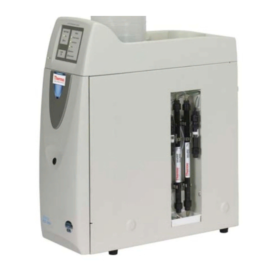
Right-Side Panel Figure 2-5 illustrates the RFIC-ER compartment on the right side of the Dionex ICS-1100. Figure 2-5. RFIC-ER Compartment (Cover Removed) The compartment houses the ER Controller (ERC 10) and various columns required for operation in the RFIC-ER mode. The ERC 10 electronics monitor the volume of electrolysis gases (such as hydrogen and oxygen) in the eluent stream. -
Page 28: Rear Panel
Figure 2-6. Dionex ICS-1100 Rear Panel Analog Output Connector The analog output connector outputs conductivity data (as a 0 to 1 V signal) to an integrator or recording device. For connection and setup information, refer to the Dionex ICS-1100 installation instructions. Doc. 065289-03 10/12... - Page 29 Tubing Chases The upper tubing chase routes tubing from the RFIC-ER compartment to the Dionex ICS-1100 rear panel. The lower chase routes tubing from the rear panel to the component panel. Tubing Clips The tubing clips hold tubing routed from the top cover in place.
-
Page 30: Flow Schematics
Dionex ICS-1100 Ion Chromatography System Flow Schematics The following figures illustrate the liquid flow path through a Dionex ICS-1100 when using suppression in autorecycle mode. Two configurations are shown: • Figure 2-7 illustrates the liquid flow path through components when performing conventional ion chromatography. - Page 31 2 • Features WASTE ELUENT COND CELL PULSE DAMPER PUMP PUMP HEAD HEAD WASTE PRESS. XDUCER Figure 2-7. Dionex ICS-1100 Flow Schematic: Standard Configuration Doc. 065289-03 10/12...
- Page 32 Dionex ICS-1100 Ion Chromatography System Flow Description for RFIC-ER Mode • Eluent from the eluent reservoir flows first through the pump degas assembly (if it is installed) and then through the eluent valve to the pump ...
- Page 33 2 • Features ERC 10 ELUENT ER3b ER3a COND CELL PULSE DAMPER PUMP PUMP HEAD HEAD WASTE PRESS. XDUCER Figure 2-8. Dionex ICS-1100 Flow Schematic: RFIC-ER Mode Doc. 065289-03 10/12...
-
Page 34: Chromeleon And Chromeleon Xpress
A Dionex ICS-1100 Control panel (see Figure 2-9) provides access to Dionex ICS-1100 functions. The label on the tab for this panel is the name of the timebase in which the Dionex ICS-1100 is configured. Figure 2-9. Dionex ICS-1100 Control Panel on the Panel Tabset... -
Page 35: Software Control Modes
• A Status panel shows the overall system status. • An Autosampler panel (included if the Dionex ICS-1100 is connected to a Dionex AS, Dionex AS-AP, Dionex AS-DV, or Dionex AS-HV Autosampler) provides access to autosampler functions. To open the panel tabset, use one of the methods below: •... -
Page 36: System Component Details
The electronics required to operate the vacuum pump • Tubing, fittings, and other accessories By default, the Dionex ICS-1100 monitors the degas pressure reading and turns the degas pump on and off as needed. Different degas operating modes can be selected from Chromeleon. - Page 37 Cycle Off between cycles. • : (default mode) The Dionex ICS-1100 monitors the degas Monitor pressure reading and turns the degas pump on and off as required. Doc. 065289-03 10/12...
-
Page 38: Eluent Valve
Figure 2-11. Eluent Valve 2.4.3 Pump The Dionex ICS-1100 pump is a microprocessor-based isocratic eluent delivery system. Its variable speed, dual-piston series design ensures pulse-free pumping for the most demanding applications. Primary Pump Head The primary pump head pumps eluent into the secondary head (see Figure 2-12). - Page 39 Inlet Check Valve Pressure Transducer Figure 2-12. Dionex ICS-1100 Pump Components Secondary Pump Head The secondary pump head delivers eluent to the remainder of the chromatography system (the injection valve, column, and detector). The waste valve is located on the front of the secondary pump head (see Figure 2-12).
-
Page 40: Injection Valve
For continued protection of the pump, replace the piston rinse seals (see Section 5.7) and O-rings in the seal wash assembly every 6 months, or whenever you replace the main piston seals for the Dionex ICS-1100 pump. 2.4.4 Injection Valve The injection valve (P/N 057968) is a six-port, electrically-activated valve. - Page 41 2 • Features LOAD POSITION INJECT POSITION Sample In Sample In To Column To Column Sample Sample Loop Loop To Waste From Pump To Waste From Pump Figure 2-13. Injection Valve Flow Schematics Eluent flows through either the Load or Inject path, depending on the valve position.
-
Page 42: Auxiliary Valve (Optional)
Dionex ICS-1100 Ion Chromatography System Figure 2-14. Injection Valve Plumbing 2.4.5 Auxiliary Valve (Optional) The auxiliary valve is a high-pressure Rheodyne valve. The electrically- activated, 2-position PEEK valve is offered in both 6-port and 10-port models (6-Port Valve Kit, P/N 069472; 10-Port Valve Kit, P/N 069473). -
Page 43: Column Heater (Optional)
2 • Features 2.4.6 Column Heater (Optional) The column heater provides temperature control for the separator and guard column. The heater temperature can be set to between 30 °C and 60 °C. However, the set temperature must be at least 5 °C above the ambient temperature. -
Page 44: Suppressor
Dionex ICS-1100. For details about any of the suppressors or for information about selecting a suppressor for your application, refer to the suppressor manuals. The manuals are on the Thermo Scientific Reference Library DVD (P/N 053891). 2.4.8 DS6 Heated Conductivity Cell The flow-through conductivity cell measures the electrical conductance of analyte ions as they pass through the cell. -
Page 45: Er Controller
(such as hydrogen and oxygen) in the eluent stream. If the predefined safety limit is exceeded, the ERC 10 shuts down the Dionex ICS-1100 pump to prevent the buildup of gases in the eluent bottle. - Page 46 Dionex ICS-1100 Ion Chromatography System Doc. 065289-03 10/12...
-
Page 47: Operation And Maintenance
Dionex ICS-1100. The Dionex ICS-1100 is designed for IC (ion chromatography) applications and should not be used for any other purpose. Operation of the Dionex ICS-1100 in a manner not specified by Thermo Fisher Scientific may result in personal injury. - Page 48 Dionex ICS-1100 Ion Chromatography System Sample Processing Overview Samples can be run manually (one at a time), or they can be grouped and run automatically in batches. Figure 3-2 shows the typical steps for manual and batch sample processing. Manual Sam ple...
-
Page 49: Turning On The System Power
Table 3-2 shows the Dionex Switch ICS-1100 conditions at power-up. Also turn on the power to the computer and the autosampler (if used). Figure 3-3. Dionex ICS-1100 Rear Panel Feature Power-Up Condition Pump Injection valve Load position Cell Reading current value... -
Page 50: Connecting To Chromeleon
Tabset or by clicking the Default Panel Tabset toolbar button. If Chromeleon Xpress is installed, starting the application automatically displays the panel tabset. 5. To display the Dionex ICS-1100 Control panel, click the tab labeled with the Dionex ICS-1100 timebase name (see Figure 3-4). - Page 51 3 • Operation and Maintenance Figure 3-4. Dionex ICS-1100 Control Panel on the Chromeleon Panel Tabset Doc. 065289-03 10/12...
-
Page 52: Set Up The Eluent Reservoir
The optional vacuum degas assembly provides programmable, online degassing. The degas assembly must be installed in the Dionex ICS- 1100 at the factory. If the Dionex ICS-1100 does not contain a degas assembly, manually degas eluent daily (following the instructions below) and store it in pressurized reservoirs. -
Page 53: Filter The Eluent
Filtering removes small particulates in the eluent that may contaminate the pump check valves and cause erratic flow rates or loss of prime. An end-line filter (P/N 045987) is provided in the Dionex ICS-1100 Ship Kit (P/N 057905) for this purpose. -
Page 54: Connect The Reservoir
In order for the level displayed in the Eluent bottle box and gauge to be accurate, you must enter the level when the reservoir is filled. The Dionex ICS-1100 does not automatically detect when the reservoir is filled, nor when it is empty. -
Page 55: Prime The Pump
Prime on the Chromeleon Control panel. The pump will begin pumping at approximately 3 mL/min. 4. Continue priming the Dionex ICS-1100 until all air and previous eluent are purged and no air bubbles are exiting the waste line. 5. Press Pump Off 6. -
Page 56: Set System Operating Conditions
Dionex ICS-1100 Ion Chromatography System Set System Operating Conditions NOTE This section is an overview of the steps needed to start up the system and begin running samples. Actual operating parameters (flow rate, cell heater temperature, suppressor current, etc.) depend on the application to be run. -
Page 57: Prepare Samples
3 • Operation and Maintenance • If the pressure is less than the expected amount, gas may be trapped in the system. To release the gas, remove the pump fitting on the injection valve port, labeled ). Allow the air to escape and then reconnect the fitting. •... -
Page 58: Pretreating Samples
Dionex ICS-1100 Ion Chromatography System time. Refrigerating the samples at 4 C (39 F) will reduce, but not eliminate, bacterial growth. Analyze samples containing nitrite or sulfite as soon as possible. Nitrite oxidizes to nitrate, and sulfite to sulfate, thus increasing the measured concentrations of these ions in the sample. -
Page 59: Loading And Injecting Samples
To use a Dionex AS-DV Autosampler with the Dionex ICS-1100, the following requirements must be met: • The Dionex ICS-1100 injection valve must be linked to the Dionex AS-DV in the Chromeleon timebase. Setup for a Dionex AS-HV Autosampler For setup information for the AS-HV Autosampler, see the AS-HV Autosampler Operator’s Manual (Document No. -
Page 60: Loading Samples With A Syringe
Dionex ICS-1100 Ion Chromatography System 3.10.1 Loading Samples with a Syringe 1. Make sure the injection port on the Dionex ICS-1100 front door (see Figure 2-1) is connected to sample port on the injection valve S (5) (see Figure 3-7). -
Page 61: Loading Samples With A Vacuum Syringe
1. Verify that the autosampler output line is connected to port of the S (5) Dionex ICS-1100 injection valve. 2. Prepare and fill the sample vials and place them in the autosampler tray or cassette. Refer to the autosampler manual for detailed instructions. -
Page 62: Injecting Samples
Summary of Manual Sample Processing 1. Complete the instructions in Section 3.2 through Section 3.8 prepare the Dionex ICS-1100 for operation and to prepare the sample for processing. 2. Load the sample, using a syringe, vacuum syringe, or autosampler (see Section 3.10). -
Page 63: Automatic (Batch) Sample Processing
3 • Operation and Maintenance Saving Manual Data NOTE Chromeleon Xpress does not allow data to be saved. If you are using Chromeleon, data from manual processing is saved in the manual sequence under the timebase folder in the local datasource. To save the data from a manual run: 1. - Page 64 Section 3.2 through Section 3.8 prepare the Dionex ICS-1100 for operation and to prepare the sample for processing. 2. If an autosampler is installed, prepare and fill the sample vials and place them in the autosampler tray or cassette. Refer to the autosampler manual for detailed instructions.
-
Page 65: Maintenance
You can also check the life expectancy of these components on the RFIC-ER Wellness panel. Daily • Check the Dionex ICS-1100 component panel (see Figure 2-4) for leaks or spills. Wipe up spills. Isolate and repair leaks (see Section 4.3). - Page 66 Yearly • Thermo Fisher Scientific recommends performing preventive maintenance annually, as well as before scheduled Performance Qualification tests. A Dionex ICS-1100 Preventive Maintenance Kit (P/N 057954) is available for this purpose. • Rebuild the auxiliary valve, if installed (see Section 5.4).
- Page 67 3 • Operation and Maintenance • If a Dionex AS-DV Autosampler is installed, replace the tip and tubing. The Dionex AS-DV Preventive Maintenance Kit (P/N 055647) contains all of the components required to replace the sampling tip and the tubing between the tip and the injection valve.
- Page 68 Dionex ICS-1100 Ion Chromatography System Doc. 065289-03 10/12...
-
Page 69: Troubleshooting
4 • Troubleshooting This chapter is a guide to troubleshooting minor issues that may arise during operation of the Dionex ICS-1100. Turn to the section of this chapter that best describes the operating problem or symptom that has been observed. Each section lists possible causes of the problem or symptom in order of probability. - Page 70 Dionex ICS-1100 Ion Chromatography System The table below lists the most frequently observed Dionex ICS-1100 error messages. For troubleshooting assistance, refer to the page indicated in the table. Alarms and Error Conditions Column heater exceeds safe temperature page 61 Column heater open circuit...
-
Page 71: Troubleshooting Error Messages
Troubleshooting Error Messages COLUMN HEATER EXCEEDS SAFE TEMPERATURE This error occurs when the column heater temperature is higher than the maximum allowed. This error may occur if the Dionex ICS-1100 is operating in an extreme environment (greater than 40 C (104 F)). - Page 72 LOAD/INJECT VALVE ERROR If the injection valve fails to switch position within 1 second of being toggled, the Dionex ICS-1100 Moduleware reports an error to Chromeleon and this error message appears. Doc. 065289-03 10/12...
- Page 73 2. Try to toggle the valve from Load to Inject by clicking the Load and Inject buttons on the Dionex ICS-1100 Control panel in Chromeleon. 3. Turn off the Dionex ICS-1100 power briefly and then restart. 4. If the problem persists, repeat Step 5.
- Page 74 PUMP STOPPED DUE TO LOST USB COMMUNICATION ERROR This error occurs if the Dionex ICS-1100 loses communication with Chromeleon. To troubleshoot: Verify that the USB cable is connected correctly from the Dionex ICS-1100 rear panel to the Chromeleon PC. Doc. 065289-03 10/12...
- Page 75 5. Restart the pump. SECOND VALVE ERROR If the auxiliary valve fails to switch position within 1 second of being toggled, the Dionex ICS-1100 Moduleware reports an error to Chromeleon and this error message appears. To troubleshoot: 1. If a sequence is being executed, terminate the sequence by selecting Batch >...
- Page 76 Dionex ICS-1100 Ion Chromatography System SUPPRESSOR NOT CONNECTED This error occurs if you turn on the suppressor and the Dionex ICS-1100 cannot establish a connection with the suppressor. To troubleshoot: 1. Check the suppressor cable connection (see Section 5.11). 2. If the error persists, contact Thermo Fisher Scientific for assistance. There may be a problem in the suppressor controller electronics.
- Page 77 3. If the error persists, replace the suppressor (see Section 5.11). SUPPRESSOR OVER VOLTAGE This error occurs if you turn on the suppressor but the Dionex ICS-1100 cannot establish a connection with the suppressor. To troubleshoot: 1. Check the suppressor cable connection (see Section 5.11).
-
Page 78: Liquid Leaks
Make sure the lines are not crimped or otherwise blocked. Also, if the blocked line is a waste line, make sure it is not elevated at any point after it exits the Dionex ICS-1100. If a line is blocked, replace it (see Section 5.2). - Page 79 5.9). • Leaking suppressor Refer to the suppressor manual for troubleshooting procedures. Suppressor manuals are included on the Thermo Scientific Reference Library DVD (P/N 053891). • Leaking injection valve or auxiliary valve 1. Make sure the liquid line connections to the transducer are tight. Refer to Installation of Dionex Liquid Line Fittings (Document No.
-
Page 80: Pump Difficult To Prime Or Loses Prime
Empty eluent reservoir and/or no eluent connected Fill the reservoir. Make sure all connections are secure. • Eluent improperly or insufficiently degassed If the Dionex ICS-1100 does not contain a vacuum degas assembly, degas the eluent manually (see Section 3.4.4). - Page 81 • Liquid leaks at junction between pump head and pump casting Use the open-end wrench (P/N 014605) provided in the Dionex ICS-1100 Ship Kit (P/N 057905) to tighten the two acorn nuts that attach the pump head to the pump housing (see Figure 5-7).
-
Page 82: Pump Does Not Start
Dionex ICS-1100 installation instructions. • Pump is turned off Turn on the pump from the Dionex ICS-1100 Control panel in Chromeleon. • Flow rate is set to 0 Set the flow rate from the Dionex ICS-1100 Control panel in Chromeleon. -
Page 83: Erratic Flow/Pressure Reading
4 • Troubleshooting • Flow rate is set to 0 Set the flow rate from the Dionex ICS-1100 Control panel in Chromeleon. • Eluent valve is closed Open the eluent valve from the Dionex ICS-1100 Control panel in Chromeleon. •... -
Page 84: Peak "Ghosting
5.1.3). • Clogged column bed supports Refer to the instructions in the column manual for troubleshooting guidance. Column manuals are included on the Thermo Scientific Reference Library DVD (P/N 053891). • Contaminated columns Clean the columns as instructed in the column manual or replace the guard column. -
Page 85: Nonreproducible Peak Height Or Retention Time
Remake the eluent. If the system is not operating in the RFIC-ER mode, refer to the instructions in the column manual. The manual is included on the Thermo Scientific Reference Library DVD (P/N 053891). If this is an RFIC-ER system, refer to the instructions in the manual provided in your RFIC-ER Installation Kit. -
Page 86: No Cell Response
3.9). • Contaminated column 1. Clean the column as instructed in the column manual. Column manuals are included on the Thermo Scientific Reference Library DVD (P/N 053891). 2. If cleaning is unsuccessful, replace the column. 4.12 No Cell Response •... - Page 87 4 • Troubleshooting guidance. Suppressor manuals are included on the Thermo Scientific Reference Library DVD (P/N 053891). • Sample concentration too high Dilute the sample (see Section 3.9.3). • Wrong eluent Check that you are using the correct eluent for your application.
-
Page 88: Baseline Noise Or Drift
Make sure the ambient temperature is between 4 and 40 °C (40 and 104 °F). Make sure air conditioning and heating vents are directed away from the Dionex ICS-1100 and the Dionex ICS-1100 front door is closed. • Insufficient system equilibration following changes to operating parameters;... -
Page 89: Vacuum Degas Assembly Does Not Run
4.15 Vacuum Degas Assembly Does Not Run • Degas option not enabled in Chromeleon 1. Open the Chromeleon Server Configuration program. Right-click the Dionex ICS-1100 device in the timebase and select Properties. 2. Select the Options tab (see Figure 4-3). - Page 90 Dionex ICS-1100 Ion Chromatography System 4. Under Degas, verify that the Always Off option is not selected. If it is, select one of the following settings instead: • Cycle; also select On: 30 seconds and Off: 10 minutes • Monitor 5.
-
Page 91: Service
5 • Service This chapter describes Dionex ICS-1100 service and repair procedures that the user can perform. All procedures not included here, including electronics-related repair procedures, must be performed by Thermo Fisher Scientific personnel. For assistance, contact Technical Support for Dionex products. In the U.S. and Canada, call 1-800-346-6390. -
Page 92: Chromeleon Wellness Panel Overview
2. Double-click ICS-1100_1600_2100_Wellness_user.pan. The Wellness Panel opens (see Figure 5-1). If the controls on the Wellness panel are disabled, select Control > Connect to timebase and then select the Dionex ICS-1100 timebase. Figure 5-1. Chromeleon Wellness Panel Doc. 065289-03 10/12... - Page 93 Calibrate the pump flow rate • Calibrate the vacuum degas assembly • Calibrate the conductivity cell • Test the conductivity cell electronics, using a dummy cell • Upload calibration values from the Dionex ICS-1100 to the Chromeleon Wellness database Doc. 065289-03 10/12...
-
Page 94: Calibrating The Conductivity Cell
Backpressure tubing to provide Use 0.076-mm (0.003-in) ID yellow PEEK at least 7 MPa (1000 psi) tubing (P/N 049715). 1. Open the Dionex ICS-1100 Wellness Panel in Chromeleon (see Section 5.1.1). 2. On the Wellness Panel under Electric Conductivity Cell Calibration, click Offset Cal. - Page 95 5 • Service After calibration, the conductivity reading should be 147.00 ± 2 and the cell constant should be between 120 and 180. If this is not the case, contact Thermo Fisher Scientific for help. 11. Click Log to record the new calibration values in the Audit Trail. 12.
-
Page 96: Calibrating The Flow Rate
Dionex ICS-1100 Ion Chromatography System 5.1.3 Calibrating the Flow Rate When to Calibrate If you run the Dionex ICS-1100 Operational Qualification or Performance Qualification and it fails. Items Needed • 0.076-mm (0.003-in) ID yellow PEEK tubing (P/N 049715) to create 14 ±... -
Page 97: Calibrating The Vacuum Degas Assembly
Calibrating the Vacuum Degas Assembly When to Calibrate • After every 6 months of use 1. Open the Dionex ICS-1100 Wellness Panel in Chromeleon (see Section 5.1.1). 2. On the Wellness Panel under Degas Calibration, select Calibrate. The degas pump runs for 90 seconds to allow a vacuum to be created. - Page 98 Dionex ICS-1100 Ion Chromatography System WASTE ELUENT COND CELL PULSE DAMPER PUMP PUMP HEAD HEAD WASTE PRESS. XDUCER Figure 5-2. Dionex ICS-1100 Flow Schematic: Standard Configuration Doc. 065289-03 10/12...
- Page 99 5 • Service ERC 10 ELUENT ER3b ER3a COND CELL PULSE DAMPER PUMP PUMP HEAD HEAD WASTE PRESS. XDUCER Figure 5-3. Dionex ICS-1100 Flow Schematic: RFIC-ER Mode Doc. 065289-03 10/12...
-
Page 100: Replacing Tubing And Fittings
Dionex ICS-1100 Ion Chromatography System Replacing Tubing and Fittings The Dionex ICS-1100 is plumbed with the tubing and tubing assemblies listed below. Tubing Size and Type Color Used For 0.125-mm (0.005-in) ID PEEK Connection from pump pulse damper (P/N 044221) to pressure transducer 0.25-mm (0.010-in) ID PEEK... -
Page 101: Rebuilding The Injection Valve Or Auxiliary Valve
Dionex Terms and Conditions for more information. 1. Turn off the pump from the Dionex ICS-1100 Control panel in Chromeleon. 2. Open the Dionex ICS-1100 front door. 3. Disconnect each liquid line connected to the valve. -
Page 102: Replacing An Auxiliary Valve Pod
Refer to the warranty statement in the Dionex Terms and Conditions for more information. 1. Turn off the pump flow from the Dionex ICS-1100 Control panel in Chromeleon. 2. Open the Dionex ICS-1100 front door. - Page 103 5-5) and remove the ring. 5. Grasp the front of the valve pod and pull firmly to remove it from the Dionex ICS-1100. Black Locking Ring Figure 5-5. Unscrew the Valve Locking Ring 6. Check that the new pod (6-port, P/N 061947; 10-port, P/N 061948) has the correct number of ports for the valve being serviced.
- Page 104 Dionex ICS-1100 Ion Chromatography System 9. Push the pod into the holder until it clicks into place. Replace the black locking ring. 10. Reconnect all liquid lines to the valve. 11. Turn on the pump flow. Check for leaks from the valve. Tighten fittings as...
-
Page 105: Cleaning And Replacing The Pump Check Valves
If new check valves are not available, follow the instructions for cleaning. Replacing Check Valves 1. Close the eluent valve from the Dionex ICS-1100 Control panel in Chromeleon. 2. Turn off the main power switch, to ensure that you do not unintentionally start the Dionex ICS-1100. - Page 106 10. Prime the pump (see Section 5.17). 11. When the Dionex ICS-1100 is at operating pressure, check for leaks from the check valves. Tighten a check valve a little more only if it leaks. Cleaning Check Valves 1. Carefully remove the check valve cartridges from the valve housings.
-
Page 107: Replacing A Pump Piston Seal And Piston Rinse Seal
2. After rinsing, close the waste valve. 3. Close the eluent valve from the Dionex ICS-1100 Control panel in Chromeleon. 4. To prevent contamination of pump parts, put on a pair of rubber gloves before disassembling the pump head. - Page 108 Dionex ICS-1100 Ion Chromatography System 5. Place the head (front end down) on a clean work surface and lift off the spacer to expose the piston seal (see Figure 5-8 Figure 5-9). Priming Valve Knob (P/N 055709) Outlet Check Valve Assembly...
- Page 109 5 • Service 6. The piston does not come off as part of the pump head assembly because it is captured by a magnetic retention system. After removing the pump head, hold the shaft of the piston (near the base), tilt the piston slightly, and pull the piston away from the pump.
- Page 110 Dionex ICS-1100 Ion Chromatography System Removing the Piston Seal from the Head 1. Fill the head cavity with deionized water by injecting the liquid through either the piston opening or the inlet check valve. 2. Reinsert the piston approximately 3 mm (0.125) inch into the seal.
-
Page 111: Replacing A Pump Piston
5 • Service Reinstalling the Head and Piston Thermo Fisher Scientific recommends reinstalling the head and piston as a single assembly, so that the piston centers itself onto the magnetic follower. 1. Hold the assembled spacer and guide with the drain tubes aligned vertically and press the spacer into the head until it is flush with the indented surface of the head. -
Page 112: Replacing The Waste Valve Or Priming Valve O-Ring
A damaged O-ring causes leakage around the base of the waste valve or priming valve knob. 1. Close the eluent valve from the Dionex ICS-1100 Control panel in Chromeleon. 2. Turn off the main power switch, to ensure that you do not unintentionally start the Dionex ICS-1100. - Page 113 5 • Service 4. If the O-ring is removed with the valve knob in Step 3, pull the O-ring off the end of the knob (see Figure 5-11). If the O-ring is not removed with the valve knob, insert a thin object (for example, the bent end of a paper clip) into the cavity in the pump head and carefully pull out the O-ring.
-
Page 114: Replacing The Conductivity Cell
Dionex ICS-1100 Ion Chromatography System 5.10 Replacing the Conductivity Cell 1. Turn off the Dionex ICS-1100 power. 2. Open the front door and disconnect the tubing from the CELL IN CELL fittings (see Figure 5-12, View A). Loosen the two screws on the cell front cover. - Page 115 Download to download the new value to the Dionex ICS- 1100. To ensure that the new values are recorded in the Dionex ICS-1100 memory, do not turn off the Dionex ICS-1100 power for at least 1 minute after downloading. Doc. 065289-03 10/12...
- Page 116 2. Turn off the pump from the Dionex ICS-1100 Control panel in Chromeleon. 3. Open the front door of the Dionex ICS-1100. 4. Disconnect the two eluent and the two regenerant lines from the suppressor.
- Page 117 Tabs on Component Panel 5.12 Replacing the Column Heater 1. Turn off the Dionex ICS-1100 power. 2. Open the front door of the Dionex ICS-1100. 3. Remove the existing column heater: a. Unscrew the two thumbscrews on the heater cover (they remain attached to the cover).
- Page 118 Dionex ICS-1100 Ion Chromatography System Thumbscrews (6) Figure 5-16. Dionex ICS-1100 Column Heater Cover Removed d. Remove the columns from the column heater. e. Pull the column heater straight toward you to remove it from the component panel. 4. Before installing the new column heater, write down the two calibration values (offset and slope) recorded on the back of the heater.
- Page 119 Dionex ICS-1100. d. To ensure the new calibration values are recorded in the Dionex ICS-1100 memory, do not turn off the Dionex ICS-1100 power for at least 1 minute after downloading the values. 5.13 Replacing the Column Heater Heat Exchanger 1.
- Page 120 11. Reinstall the top metal plate and the heater cover. 5.14 Replacing the Eluent Valve 1. Turn off the power to the Dionex ICS-1100. 2. Open the Dionex ICS-1100 front door. 3. To prevent an eluent leak during the valve replacement procedure, disconnect...
- Page 121 Step Figure 5-20. Removing the Eluent Valve Mounting Plate 11. Connect the cable from the new valve (P/N 057945) to the Dionex ICS-1100 cable. Feed the cables back inside the Dionex ICS-1100. Doc. 065289-03 10/12...
- Page 122 12. Align the new valve on the component panel with the liquid ports facing up and attach it with the two screws removed in Step 5. Reconnect the liquid lines. 13. Turn on the power to the Dionex ICS-1100. 14. Prime the pump (see Section 5.17). 5.15 Replacing the Leak Sensor 1.
- Page 123 7. Connect the cable from the new leak sensor (P/N 058053) to the Dionex ICS- 1100 cable. 8. Feed the cables back inside the Dionex ICS-1100. Align the leak sensor with the component panel opening and fingertighten the screw. 9. Make sure the leak sensor does not touch the bottom of the drip tray.
- Page 124 Figure 5-23. Priming the Eluent Lines 3. Open the priming valve by turning it one-quarter to one-half turn counterclockwise. 4. On the Dionex ICS-1100 Control panel in Chromeleon, click the Pump Settings button. The Pump Settings window opens (see Figure 3-5).
- Page 125 Confirm that the waste valve is open by clicking OK when the reminder message appears. The pump will begin pumping at about 3 mL/min. 4. Continue priming the Dionex ICS-1100 until no air bubbles are exiting the pump waste line. 5. In the Pump Settings window, click Pump Off.
- Page 126 Dionex ICS-1100 Ion Chromatography System 5.17 Priming the Pump with Isopropyl Alcohol NOTE Prime the pump heads with isopropyl alcohol only if the standard priming procedures described Section 5.16 are unsuccessful. 1. Connect a 10 mL syringe (P/N 079803) filled with...
- Page 127 2. The fuse holder is part of the main power receptacle (see Figure 5-26) on the Dionex ICS-1100 rear panel. To remove the fuse holder, squeeze the tab on the top of the holder to release it and pull the holder straight out of its compartment.
- Page 128 Dionex ICS-1100 Ion Chromatography System 3. Replace the two fuses in the holder with new IEC 127 fast-blow fuses rated 3.15 amps (P/N 954745). Thermo Fisher Scientific recommends always replacing both fuses. 4. Reinsert the fuse holder into its compartment and push in until the tab clicks in place.
- Page 129 A • Specifications A.1 Electrical Main Power 100 to 240 Vac, 50 to 60 Hz (Auto-sensing power supply; no manual voltage or frequency adjustment required) Fuses Two 3.15 amp fast-blow IEC 127 fuses (P/N 954745) A.2 Physical Dimensions Height: 56.1 cm (22.1 in) (Without Width: 22.4 cm (8.8 in) reservoir)
- Page 130 Dionex ICS-1100 Ion Chromatography System A.3 Environmental Operating 4 to 40 °C (40 to 104 °F); cold room-compatible (4 °C) as long Temperature as system power remains on Operating 5% to 95% relative humidity, noncondensing Humidity Operating Pressure 35 MPa (5000 psi) maximum liquid path (tubing, valve, columns, etc.)
- Page 131 A • Specifications Pressure Ripple <1% at 13.8 MPa (2000 psi) and 1.0 mL/min Eluent On/Off Standard feature Valve Piston Seal Dual-pump head; wash can be continuous when connected to rinse Wash solution supply • Pressure Alarm Upper limit: 0 to 35 MPa or 0 to 5000 psi in one unit (MPa or Limits psi) increments •...
- Page 132 Dionex ICS-1100 Ion Chromatography System A.6 Eluent Regeneration Eluent Optional feature; RFIC-ER Startup Kit required Regeneration • Eluents Carbonate and carbonate/bicarbonate up to 20 mM • MSA up to 34 mM Flow Rates 0.01 to 2.00 mL/min Continuous Up to 28 days or 2000 samples, typically...
- Page 133 A • Specifications • Digital signal range: 0 to 15,000 S Full-Scale • Output Ranges Analog signal range: 0 to 15,000 S ±0.1 nS/cm when background conductivity is 0 to 150 S/cm Electronic Noise ±2 nS/cm when background conductivity is 151 to 3200 S/cm Filter Rise times from 0 to 10 s;...
- Page 134 Dionex ICS-1100 Ion Chromatography System A.10 Auxiliary Valve Optional) Auxiliary Valve 6-port or 10-port, 2-position Rheodyne valve with PEEK wetted components; electrically-activated A.11 Vacuum Degas Assembly (Optional) Channel Single-channel degas channel with degas membranes Pump Dual-stage diaphragm vacuum pump Materials Wetted materials, PEEK, PTFE A.12 Column Heater (Optional)
- Page 135 A • Specifications A.13 Suppressors Chemical 2 mm and 4 mm anion and cation, membrane suppression bed types Suppression Displacement 2 mm and 4 mm anion and cation, membrane suppression bed types Chemical Regeneration • Electrolytic Self-Regenerating: 2 mm and 4 mm anion and cation; both ™...
- Page 136 Dionex ICS-1100 Ion Chromatography System SRS 300 (4 mm): <50 L Void Volume SRS 300 (2 mm): <15 L MMS 300 (4 mm): <50 L MMS 300 (2 mm): <15 L AMMS ICE 300 (4 mm): <50 L AMMS ICE 300 (2 mm): <15 L Anion AES: <35 L...
- Page 137 A • Specifications Data Trending Numerical device parameters can be plotted Plots • Virtual Column Evaluation mode: Standard feature • Simulator Isocratic and gradient modes: Optional features Application Standard feature Templates Automation Fully controls over 300 different instruments from more than 30 Support for manufacturers, including GC, HPLC, and MS Third-Party...
- Page 138 Dionex ICS-1100 Ion Chromatography System Customized Standard feature; unlimited report workbooks Reporting Automated Detailed, comprehensive qualification reports System Qualification Doc. 065289-03 10/12...
- Page 139 B • TTL and Relay Control B.1 TTL and Relay Connections A 12-pin connector strip for TTL/relay control is located on the Dionex ICS-1100 rear panel. The connector provides two relay outputs, two TTL outputs, and four TTL inputs (see Figure B-1).
- Page 140 Dionex ICS-1100 Ion Chromatography System The outputs can be used to control functions in external devices such as an autosampler or another Dionex module. When connected to a controlling device, the inputs can be programmed to perform the following Dionex ICS-1100 functions: •...
- Page 141 B • TTL and Relay Control b. Plug the connector into the 12-pin connector on the Dionex ICS-1100 rear panel. c. Connect the wires from the Dionex ICS-1100 connector plug to the TTL or relay connector pins on the other module(s). Additional connector plugs are provided with other Dionex modules.
- Page 142 , is compatible with the output signals provided by Dionex modules. If the device connected to the Dionex ICS-1100 does not send a normal edge signal, select the appropriate control type. Refer to the documentation provided with the controlling device and the information below to select the correct type.
- Page 143 B • TTL and Relay Control • Normal Edge: In normal edge operation, the negative (falling) edge of a signal turns on the function. For example, for the function, the Load/Inject negative edge switches the injection valve position to Load. The action of the positive (rising) edge depends on the function: For function, the rising edge switches the injection valve Load/Inject...
- Page 144 Dionex ICS-1100 Ion Chromatography System B.2 Controlling TTL and Relay Outputs The Dionex ICS-1100 provides two TTL outputs and two relay contacts for control of functions in external devices, such as an integrator or autosampler. The relay outputs can be used to switch any low-voltage control. Switched current must be less than 200 mA and 60 V peak blocking.
- Page 145 C • Reordering Information Part Number Item Reservoirs 046548 2-L plastic reservoir assembly (includes stopper and cap) 039164 4-L plastic reservoir assembly (includes stopper and cap) Pump 057937 Primary pump head assembly 057938 Secondary pump head assembly 045721 Outlet check valve assembly, 10-32 045722 Inlet check valve assembly, 1/4-28 045994...
- Page 146 Dionex ICS-1100 Ion Chromatography System Part Number Item 061947 Auxiliary valve pod assembly (6-port valve) 061948 Auxiliary valve pod assembly (10-port valve) Suppressors, Cell, and Column Heater 056116 Dionex AAES Anion Atlas Electrolytic Suppressor 056118 Dionex CAES Cation Atlas Electrolytic Suppressor...
- Page 147 C • Reordering Information Part Number Item Preventive Maintenance Kits 057954 Dionex ICS-1100 Preventive Maintenance Kit 060581 Dionex AS Preventive Maintenance Kit 055647 Dionex AS-DV Preventive Maintenance Kit Doc. 065289-03 10/12...
- Page 148 Dionex ICS-1100 Ion Chromatography System Doc. 065289-03 10/12...
- Page 149 D • FAQ D.1 How do I hook up an autosampler? For instructions on how to connect the Dionex ICS-1100 to an autosampler, refer to the Dionex ICS-1100 installation instructions. Also refer to the autosampler operator’s manuals, which are included on the Thermo Scientific Reference Library DVD (P/N 053891).
- Page 150 In Chromeleon, select File > Export/Backup. Back up the data and indicate the backup source. D.10 How do I shut off the system? In Chromeleon, click the System Shutdown button on the Dionex ICS-1100 Control panel. On the instrument, turn off the power switch on the rear panel (see Figure 2-6).
- Page 151 Control panel. • The suppressor needs regeneration. See the suppressor manual for troubleshooting information. The suppressor manual is included on the Thermo Scientific Reference Library DVD (P/N 053891). • The cell is out of calibration. See Section 5.1.2 for calibration instructions.
- Page 152 Dionex ICS-1100 Ion Chromatography System Doc. 065289-03 10/12...
- Page 153 E • Glossary Analytical Column Synonymous with Separator Column. Band Spreading The broadening of the sample band as it travels through the column. Band spreading can also occur in the injection valve, detector cell, and interconnecting tubing. Calibration Curve A graph showing detector response in peak height or area versus analyte concentration.
- Page 154 Dionex ICS-1100 Ion Chromatography System Cell Constant (k) A factor determined experimentally by measuring the conductance (G) of a standard solution of known equivalent conductivity (k). G The value of k depends upon the surface area of, and distance between, the electrode faces in the conductivity detector cell.
- Page 155 E • Glossary of relatively clean sample. This allows large volumes of sample to be injected, lowering concentration detection limits. Conductivity A measure of the ease with which electrical current flows through a liquid contained between two opposite charged electrodes. Conductivity is a characteristic of ions in solution.
- Page 156 Dionex ICS-1100 Ion Chromatography System Packing The material that fills a chromatographic column; usually a resin or silica-based material. Pellicular Resin A resin with a solid, nonporous core coated with a thin layer of more porous material. The exchange sites of pellicular ion exchange resins are located only on the surface layer of the bead.
- Page 157 E • Glossary Siemens (S) Unit measure of conductance; the reciprocal of the electrical resistance of a solution. Suppressor A device used to minimize eluent conductivity and convert sample species to a common form, thus increasing detection sensitivity. Temperature Coefficient The percent of change in the conductivity of a solution with a 1 C change in temperature.
- Page 158 Dionex ICS-1100 Ion Chromatography System Doc. 065289-03 10/12...
- Page 159 Index Does not switch position, 65 Installation instructions, 32 Air particulate samples, 48 Leaking, 69 Alarm conditions, 61 – 67 Maintenance, yearly, 56 See also Error messages Passages blocked, 74 Ambient temperature, 78 Rebuilding, 91 Analog output, 130 Reordering, 135 Connector, 18 Replacing the mechanical part (pod), 91 –...
- Page 160 Dionex ICS-1100 Ion Chromatography System Cation separations, 47 Conductivity cell, 15, 34 Cell Calibrating, 84 See Conductivity cell Calibration constant, 105 Cell calibration, 84 High cell output, 76 Check valves Leaking, 69 Cleaning procedure, 95 – 96 No response, 76 Replacement procedure, 95 –...
- Page 161 Index Calibration, 122 Audit Trail description, 59 Cell drive, 122 Column heater exceeds safe temperature, Control and data evaluation, 122 Linearity, 122 Column heater open circuit, 61 Range, 122 Column heater short circuit, 61 Resolution, 122 Degas calibration failed, 61 Temperature compensation, 122 Hardware not present, 62 Diagnostics, 81...
- Page 162 Dionex ICS-1100 Ion Chromatography System Replacement, 112 Leaks Ghosting, 74 Auxiliary valve, 69 Guard column, 16 Cell, 69 Fittings, 68 Injection valve, 69 Liquid, 68 Pressure transducer, 69 Hardware not present error, 62 Pump check valve, 68 Heater, column, 33...
- Page 163 Index PGM file See Programs Offsetting background conductivity, 46 Physical specifications Operating features, 11 Decibel level, 119 Operating humidity, 120 Dimensions, 119 Operating ranges Weight, 119 Cell heater, 15 Piston seals Column heater, 16 Replacement procedure, 97 – 98 Flow rate, 15 Pistons Operating temperature, 120 Replacement procedure, 101...
- Page 164 Dionex ICS-1100 Ion Chromatography System Programs (Chromeleon), 25 Controlling an autosampler, 51 Rear panel, 18 Pulse damper, 20, 22, 30 Analog output connector, 18 Pump, 28 Power receptacle, 19 Flow rate, 15 USB connections, 19 Leaks, 68 Rebuilding the auxiliary valve, 91...
- Page 165 Index Sample processing, 38, 52 – 53 Waste valve O-ring replacement, 102 Batch, 38, 53 Software control, 24 Manual, 38, 52 Modes of, 25 With Chromeleon, 52 – 53 Software specifications Samples Application templates, 126 Collecting and storing, 47 Automated procedure wizards, 126 Diluting, 48 Automation support for third-party Filtering, 47...
- Page 166 Dionex ICS-1100 Ion Chromatography System Replacement procedure, 106 Baseline noise or drift, 78 Suppressor alarms Calibrations, 81 Suppressor not connected, 66 Diagnostics, 81 Suppressor over current, 66 Error messages, 61 Suppressor over power, 67 Excessive backpressure, 73 Suppressor stopped for zero flow rate, 67...
- Page 167 Index Troubleshooting, 70 Valve See Auxiliary valve See Eluent valve See Injection valve See Waste valve Warranty, voiding, 81, 91 – 92 Waste lines Blocked, 68 Waste valve, 29 Opening, 29, 97 O-ring replacement procedure, 102 Water samples, 48 Weekly maintenance, 56 Weight, 119 Wellness, 25 Wellness panel, 81...
- Page 168 Dionex ICS-1100 Ion Chromatography System Index-10 Doc. 065289-03 10/12...