Table of Contents
Quick Links
| Page 1 | TOC | May-29-2020 11:33 |
Table of Contents
1
1.1
About this Manual ............................................................................................................3
1.2
Standards and Compliance ...........................................................................................4
1.3
Safety ....................................................................................................................................5
2
2.1
General Overview ...........................................................................................................11
2.2
Functional Overview ......................................................................................................12
2.3
Overview of Components ............................................................................................13
2.4
DS-200iQ / DS-600iQ Configurations .....................................................................16
2.5
Powering on the System ..............................................................................................18
3
3.1
IMOS Control Panel ........................................................................................................23
3.2
Menu Screen .....................................................................................................................25
3.3
Jobs Screen .......................................................................................................................46
3.4
Run Screen ........................................................................................................................47
3.5
Help Menu .........................................................................................................................57
3.6
Users Screen ....................................................................................................................59
3.7
IMOS F-Keys ....................................................................................................................62
4
4.1
Creating a Job ..................................................................................................................71
4.2
Define Mailset ..................................................................................................................72
4.3
Place Mailset ....................................................................................................................85
4.4
Fold Settings ....................................................................................................................86
4.5
Mail Sorting .......................................................................................................................91
4.6
Output Placement ..........................................................................................................96
4.7
Output Settings ...............................................................................................................97
4.8
Saving the Job ...............................................................................................................106
5
5.1
Setting up a Job ............................................................................................................111
5.2
Fine Tuning a Job .........................................................................................................139
1
9
21
69
109
Chapters
Table of Contents
Troubleshooting

Related Manuals for quadient DS-200iQ


Summary of Contents for quadient DS-200iQ
-
Page 1: Table Of Contents
Standards and Compliance ...................4 Safety ............................5 Introduction General Overview ......................11 Functional Overview ......................12 Overview of Components ....................13 DS-200iQ / DS-600iQ Configurations ..............16 Powering on the System ....................18 Intergrated Mail Operating System (IMOS) IMOS Control Panel ......................23 Menu Screen ........................25 Jobs Screen ........................46 Run Screen ........................47... - Page 2 | Page 2 | TOC | May-29-2020 11:33 | Running a Job ........................150 Operator Maintenance Cleaning the Machine ....................159 Clearing Paper Jams ....................173 Changing Feed Tyres and Pickup Rollers ............180 Maintaining the Wetter System ................188 Troubleshooting Guide General Troubleshooting ...................193 Insert Head Troubleshooting ...................194 Versatile Feeder Troubleshooting ................195 Flex Folder Troubleshooting ..................196...
-
Page 3: Safety Standards Compliance
| Page 1 | Safety Standards Compliance | May-29-2020 11:33 | Safety Standards Compliance WARNING Improper installation, use, adjustment, alteration, service and or maintenance may result in property damage and or serious bodily injury! Ensure all safety information detailed in section Safety on page 5 including it’s sub-sections are read and understood in it’s entirety before installation, operation,... -
Page 5: About This Manual
| Page 3 | | May-29-2020 11:33 | About this Manual Disclaimer The data contained herein is the most current known to the manufacturer at the time of preparation and is believed to be accurate. It should not be construed as guaranteeing specific properties of the products as described or suitability for a particular application. -
Page 6: Standards And Compliance
| Page 4 | May-29-2020 11:33 | Standards and Compliance Safety and Legal Markings Environmental Legal Compliance This product complies with EU Directive 2012/19/EU, Waste of Electrical and Electronic Equipment (WEEE), in all EU member states. This product complies with EU Directive 2011/65/EU, Restriction of Hazardous Substances (RoHS), in all EU member states. -
Page 7: Safety
| Page 5 | | May-29-2020 11:33 | Safety The information presented in this section is given as a guide to general precautions and safety procedures that should be exercised during installation, operation, maintenance and or servicing of this machine. Whilst every effort has been made to ensure completeness of this document, owners, operators, and service technicians of this machine are reminded of their responsibilities to comply with all relevant legislations including Risk/COSHH Assessments if applicable... - Page 8 | Page 6 | May-29-2020 11:33 | Caution - Heavy Object Indicates the object is heavy, adhere to the safety instructions for provisions of lifting and moving. Caution - Fuse Identifies equipment that is fused. Observe correct fuse ratings where possible before replacing.
- Page 9 | Page 7 | May-29-2020 11:33 | General Safety Notes WARNING • Keep the work area around the machine clean. A minimum one metre of clear unobstructed working space is always required around the machine. • The machine must be used only as intended by the manufacturer and should not be tampered with or altered in any form.
- Page 10 | Page 8 | May-29-2020 11:33 | Power Connections Safety Notes WARNING • Ensure any isolation or disconnect device, including the mains power supply remain unobstructed at all times. • Ensure the mains power cable and its connectors are sound and undamaged. Should any electrical cable become damaged do not operate the machine, and ensure any damaged electrical cable is replaced with a correctly certified and rated replacement by the manufacturer.
-
Page 11: Introduction
| Page 9 | Introduction | May-29-2020 11:33 | Introduction General Overview ..............11 Functional Overview ..............12 Overview of Components ............13 DS-200iQ / DS-600iQ Configurations ........16 Powering on the System ............18... -
Page 13: General Overview
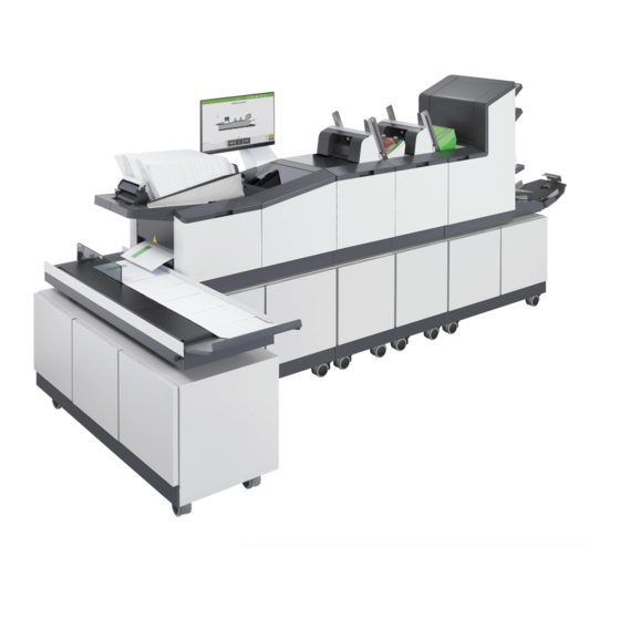
| Page 11 | | May-29-2020 11:33 | General Overview The DS-200iQ / DS-600iQ machine is a high-volume Inserter/Folder. It is of modular construction and as a basic configuration it consists of an Insert Head, with a feeding unit fitted such as a Versatile Feeder or a Flex Folder. -
Page 14: Functional Overview
| Page 12 | May-29-2020 11:33 | Functional Overview The function of the DS-200iQ / DS-600iQ machine is to fold forms to 'C', 'Z', 'V' or double forward fold, either separately, in fixed multiples or in varying groups. Enclosures such as inserts, reply envelopes etc. may be added. -
Page 15: Overview Of Components
| Page 13 | | May-29-2020 11:33 | Overview of Components An overview of the main components of the DS-200iQ / DS-600iQ are identified below. Insert Head Components Insert Head collates all documents in a pocket before insertion, feeds the envelope, inserts the pack and seals the flap. - Page 16 | Page 14 | May-29-2020 11:33 | Versatile Feeder Components Versatile Feeder is a track mounted unit, with an end-station variant also available. Up to 8 Versatile Feeder units may be fitted (7 if a Flex Folder unit is fitted). It feeds enclosures such as short-form inserts (cards, reply envelopes, booklets), flyers etc, onto the track for subsequent insertion.
- Page 17 | Page 15 | May-29-2020 11:33 | Output Conveyor Components Output Conveyor is an output device intended for use with a Sorter, Franker, Envelope Printer, and or Inserter to provide a means of receiving filled envelopes prior to hand removal for subsequent further handling, and may be fitted in two possible orientations. Speed of the Output Conveyor can be adjusted within IMOS for the relevant job, and batches can be ‘jogged’...
-
Page 18: Ds-200Iq / Ds-600Iq Configurations
| Page 16 | May-29-2020 11:33 | DS-200iQ / DS-600iQ Configurations DS-200iQ / DS-600iQ may be configured in various configurations and with various options dependent upon what units have been ordered. Image below shows an example configuration with the following units installed: •... - Page 19 | Page 17 | May-29-2020 11:33 |...
-
Page 20: Powering On The System
| Page 18 | May-29-2020 11:33 | Powering on the System Both the machine and PC must be switched on independent of each other. To power on the machine, first press the I/O toggle switch at the rear bottom right panel of the Insert Head as shown below. - Page 21 | Page 19 | May-29-2020 11:33 | Then press the front I/O power button located at the front bottom left panel of the Insert Head as shown below. A green LED indicates that the machine is switched on/powering Open the cupboard below the Insert Head to access the PC, and press the I/O button on the PC to power it on.
-
Page 23: Intergrated Mail Operating System (Imos)
| Page 21 | Intergrated Mail Operating System (IMOS) | May-29-2020 11:33 | Intergrated Mail Operating System (IMOS) IMOS Control Panel ..............23 Menu Screen ................25 System Security Level ....................29 Archive Data ........................30 Languages ........................31 Machine Id ........................32 Machine Name .......................33 Generate Licence File ....................34 Diagnostics ........................38 Jobs Screen ..................46... - Page 24 | Page 22 | Intergrated Mail Operating System (IMOS)May-29-2020 11:33 | F5 Key ..........................65 F6 Key ..........................66 F7 Key ..........................66 F8 Key ..........................67 F9 Key ..........................67...
-
Page 25: Imos Control Panel
| Page 23 | | May-29-2020 11:33 | IMOS Control Panel The IMOS control panel as shown below is the main user interface between the operator and the machine. The user interface allows access from hardware and unit set-ups, to setting up and running jobs. - Page 26 | Page 24 | May-29-2020 11:33 | Jobs screen • Selecting or editing an existing job • Defining and creating a new job Run screen • Running or stopping a job • Fine tuning a job Help • Help, and Remote assistance Users / Shut-down •...
-
Page 27: Menu Screen
| Page 25 | | May-29-2020 11:33 | Menu Screen To access the Menu screen, press the Menu button located in the top right of the control panel as indicated below. Access to the Menu screen is only available once logged in as a Supervisor or Engineer. - Page 28 | Page 26 | May-29-2020 11:33 | Libraries Libraries list the available existing OMR, BCR, Documents, Envelopes, and Postal Products that have been defined and available for use when defining a mailset. Existing definitions within the library can be copied and edited if needed, as well as the option for creating new definitions.
- Page 29 | Page 27 | May-29-2020 11:33 | OMR Definitions Library For further information on OMR definitions see section Reading Specifications on page 224. To create new OMR definitions to be used for documents when defining a mailset, contact your local Support Engineer. BCR Definitions Library For further information on BCR definitions see section Reading Specifications...
- Page 30 | Page 28 | May-29-2020 11:33 | Admin Settings - Supervisor Admin settings can only be accessed by a Supervisor, by selecting Admin under Services within the Menu screen as shown below. Admin settings allow access to the following functions and settings: •...
-
Page 31: System Security Level
| Page 29 | May-29-2020 11:33 | System Security Level System Security allows security levels to be set for the machine. To set a security level, select a level from the list, and press Ok once complete as shown below. Table below shows the security level options available, and an example list of certain operations and features available to each associated security level. -
Page 32: Archive Data
| Page 30 | May-29-2020 11:33 | Archive Data Archive Data allows the backup of IMOS system files (Libraries, Users, and Jobs data) in case of lost or corrupt critical IMOS files due to pc failure or malfunction. Select Archive Data located under Admin services within the Menu screen and browse for a folder in the dialog box, press Ok once complete as shown below. -
Page 33: Languages
| Page 31 | May-29-2020 11:33 | Languages Languages allows the choice of which language IMOS will display when operating or servicing the machine. To set a language, select an available language from the list, and press Ok once complete as shown below. -
Page 34: Machine Id
| Page 32 | May-29-2020 11:33 | Machine Id Machine Id allows the user to assign a Id for the machine using the on-screen keypad as shown below, press Ok once complete. Multiple machines on the same site should have different Machine ID's. -
Page 35: Machine Name
| Page 33 | May-29-2020 11:33 | Machine Name Machine Name allows the user to assign a name for the machine using the on-screen keypad as shown below, press Ok once complete. Multiple machines on the same site should have different Machine Name's, and must not contain any spaces. -
Page 36: Generate Licence File
| Page 34 | May-29-2020 11:33 | Generate Licence File Generate Licence File allows the generation of a blank Licence_IMOS.ini file to be used for upgrading by your local support service team, and will erase any existing licences on the machine. Press Ok once complete as shown below. - Page 37 | Page 35 | May-29-2020 11:33 | Licenced Features Licenced Features displays the current features licenced and unlicenced (if applicable) on the machine as shown below. See section Reading Specifications on page 224 for further information regarding the reading licencing of Barcodes and OMR marks.
- Page 38 | Page 36 | May-29-2020 11:33 | Imported Files Imported Files displays details of Custom Flex_barcodes imported into IMOS as shown below. Details are not shown if there are no files imported, or if no Flexbarcode licence on the machine.
- Page 39 | Page 37 | May-29-2020 11:33 | Service Settings - Supervisor Supervisor Service settings can be accessed by selecting Service under Services within the Menu screen as shown below. Supervisor Service settings allow access to the following functions and settings: •...
-
Page 40: Diagnostics
| Page 38 | May-29-2020 11:33 | Diagnostics Diagnostics allows the Supervisor to access analog sensor calibration. Analog sensors are those that respond over a graduated range, unlike digital sensors which are read as either On or Off. To adjust the analog sensors, Diagnostics from the list of services, then select the Analog sensors tab at the top of the diagnostics screen. - Page 41 | Page 39 | May-29-2020 11:33 | Typical Sensor Values Generally, readings are best used as a comparison guide for like sensors from one machine to another, however, if a sensor has failed, the readings are likely to be very low or zero.
- Page 42 | Page 40 | May-29-2020 11:33 | Insert Head Analog sensors The image below shows typical analog sensor values for the Insert Head. Wetter fluid sensor will always show a typical value above 4.5V (Blocked) because it is detecting fluid.
- Page 43 | Page 41 | May-29-2020 11:33 | Versatile Feeder Analog sensors The image below shows typical analog sensor values for the Versatile Feeder.
- Page 44 | Page 42 | May-29-2020 11:33 | Flex Folder Analog sensors The image below shows typical analog sensor values for the Flex Folder.
- Page 45 | Page 43 | May-29-2020 11:33 | Output Sorter Analog sensors The image below shows typical analog sensor values for the Output Sorter.
- Page 46 | Page 44 | May-29-2020 11:33 | Turner Analog sensors The image below shows typical analog sensor values for the Turner. System Options System Options allows the following system options to be set: Disable Machine Idle Powerdown • No • Yes If No is selected, the machine and PC will be set to automatically power-down after 60 minutes of idling (no activity), and when in an auto ended state.
- Page 47 | Page 45 | May-29-2020 11:33 | • IXXAT • Neopost Determines which type of Controller Area Network (CAN) interface device to be used. Remote Assistant Path Sets the path to be used when accessing Remote Assistant. Press Ok once complete as shown below.
-
Page 48: Jobs Screen
| Page 46 | May-29-2020 11:33 | Jobs Screen The Jobs screen shown in image below is displayed once logged into IMOS, and may be accessed anytime by pressing the Jobs button in the IMOS control panel. The Jobs screen allows the user to select a job to run, create a new job, copy, edit or delete an existing job from the jobs list. -
Page 49: Run Screen
| Page 47 | | May-29-2020 11:33 | Run Screen The Run screen is displayed once a job has been accepted in the Jobs screen, or by pressing the Run button in the IMOS control panel indicated below. - Page 50 | Page 48 | May-29-2020 11:33 | • Run button resumes the current job. Pause / Stop • Pause / Stop button stops the machine after processing the current envelope only. Autoend • Autoend button stops the machine after processing all documents in the paper path.
- Page 51 | Page 49 | May-29-2020 11:33 | Testing the Mailset Options for testing the mailset as shown below may be accessed by pressing the Single Cycle button on the Run screen. These options allow various adjustments to be made before beginning the job, in order to minimise insertion crashes.
-
Page 52: Present At Exit
| Page 50 | May-29-2020 11:33 | Present at Exit Present at Exit allows the operator to check the contents of envelopes to determine if the correct and or amount of documents are fed, and to check the address alignment. After pressing Present at exit, the first mail-piece will be processed and the machine will stop to allow the operator to adjust the vertical alignment of the address. -
Page 53: Finger Sequence
| Page 51 | May-29-2020 11:33 | Finger Sequence After pressing Finger Sequence, the machine will feed an envelope into position. This allows the operator to set the order of the insertion fingers in the envelope as demonstrated below. Make any adjustments as necessary by following the procedure below: Open the operator side cover to view the fingers. -
Page 54: Envelope Stop Position
| Page 52 | May-29-2020 11:33 | Select the required Finger Sequence from the list of options as shown below and press Ok. Press the Fingers button to operate the fingers and to view the insertion fingers adjustments in the envelope. If required, press Revert to revert back to the original Outers first (default) finger sequence setting. - Page 55 | Page 53 | May-29-2020 11:33 | Make any adjustments as necessary by following the procedure below: Use the '-' or '+' button to adjust the position. '+' Moves the envelope further into insert position. If required, press Revert to revert back to the default setting. Press Exit once the desired settings have been made.
-
Page 56: Job Count Settings
| Page 54 | May-29-2020 11:33 | Finger Adjust After pressing Finger Adjust, the machine will feed an envelope into position. This allows the operator to adjust the width of the outer fingers as demonstrated below. Make any adjustments as necessary by following the procedure below: Use the '-' or '+' button to adjust the width of the outer fingers. -
Page 57: Batch Count Settings
| Page 55 | May-29-2020 11:33 | Current job count will display until the job has been changed, even if the machine has been switched off and back on again. Press the Reset button to zero the count if required. Press Change total to set the total for the job. - Page 58 | Page 56 | May-29-2020 11:33 | Set batch mode from the list of options: - Stop - Continue Continue will pause the machine for the specified batch complete pause time, then resume, however the conveyor will continue to run during the pause time. Stop will stop the machine, press Run to resume.
-
Page 59: Help Menu
| Page 57 | | May-29-2020 11:33 | Help Menu The Help menu can be accessed anytime by pressing the Help drop-down button in the IMOS control panel indicated below. The available options from the Help menu are as follows: •... -
Page 60: Remote Assistant
| Page 58 | May-29-2020 11:33 | Remote Assistant Remote Assistant allows the machine's PC to be remotely accessed by an engineer using TeamViewer. This can help with diagnosing problems. To use Remote Assistant, contact your local support specialist, then start Remote Assistant, accessed from the Help drop-down in the IMOS control panel. -
Page 61: Users Screen
| Page 59 | | May-29-2020 11:33 | Users Screen The Users screen is accessed by pressing the Users button in the IMOS control panel indicated below. -
Page 62: Switching Users
| Page 60 | May-29-2020 11:33 | Switching Users To switch users, select the user from the users list and press Log On, located in the bottom right corner of the Users screen. Available functions and access rights will depend on who you log on as. Switching to an Engineer or Supervisor user requires a password. - Page 63 | Page 61 | May-29-2020 11:33 | User Access Rights Users are allocated different levels of access rights to allow or disallow certain functions, e.g. change settings, libraries, hardware/unit setup etc. Access rights available to a specific user will depend on the user level. Three levels of access rights can be allocated to each user as shown in table below.
-
Page 64: Imos F-Keys
F-Key functions can be used to access certain tasks within IMOS depending on the user type logged on. Access permissions to F-Key functions available to each user type is shown in table below. F10, F11, and F12 Keys are currently not used for any function on DS-200iQ and DS-600iQ machines. -
Page 65: F1 Key
| Page 63 | May-29-2020 11:33 | F1 Key Press F1 to access the machine Operator documentation. F2 Key Press F2 to view General Information of the machine as shown below. -
Page 66: F3 Key
| Page 64 | May-29-2020 11:33 | F3 Key Press F3 to access the following F3 Key functions as shown below. - Capture Trace - Allows the retrieval of firmware trace data for selected units as shown below. -
Page 67: F4 Key
| Page 65 | May-29-2020 11:33 | F4 Key Press F4 to show the Batch, Jog, and Divert counters as shown below. F5 Key Press F5 to access the following Engineer and Factory F5 Key functions as shown below. -
Page 68: F6 Key
| Page 66 | May-29-2020 11:33 | F6 Key Press F6 to access the following Diagnostics F6 Key functions used by Factory R&D and Field Technicians as shown below. Envelope Only mode is used for diagnostics only. F7 Key Press F7 to view Output log information of mail pieces as they reach the output of the machine as shown below. -
Page 69: F8 Key
| Page 67 | May-29-2020 11:33 | F8 Key Press F8 to view Input log information of mail pieces at the input of the machine as shown below. F9 Key Press F9 to access Debug information used by Factory R&D and Field Technicians as shown below. -
Page 71: Operator Imos Settings
| Page 69 | Operator IMOS Settings | May-29-2020 11:33 | Operator IMOS Settings Creating a Job ................71 Define Mailset ................72 Envelope Mailset ......................73 Creating a New Envelope ..................75 Document Mailset ......................77 Creating a New Document ..................81 Enclosure Mailset ......................84 Advanced Envelope Mailset Settings ..............74 Advanced Document Mailset Settings ..............79 Place Mailset ................85... -
Page 73: Creating A Job
| Page 71 | | May-29-2020 11:33 | Creating a Job Before creating a job, settings must first be defined for the following: • Define Mailset (Envelope, Document, and Enclosures) • Place Mailset • Fold Settings • Mail Sorting • Output Placement •... -
Page 74: Define Mailset
| Page 72 | May-29-2020 11:33 | Define Mailset To begin defining the mailset, press New in the Jobs screen as shown below. -
Page 75: Envelope Mailset
| Page 73 | May-29-2020 11:33 | Envelope Mailset To select an existing envelope for the mailset, press Select to open the Envelopes selection box, then select the required envelope from the list and press Ok as shown below. If required, press Settings to define the envelope usage (Seal mode) as shown below. -
Page 76: Advanced Envelope Mailset Settings
| Page 74 | May-29-2020 11:33 | Select the required Seal mode from the list (default set to Always). Other options include the following: - Off - Envelope is left unsealed with flap closed. - No-seal label select - Reads no-seal character in label. - Off, flap open - Envelope is left unsealed with flap open (not available if an Output Sorter is fitted). -
Page 77: Creating A New Envelope
| Page 75 | May-29-2020 11:33 | Creating a New Envelope To create a new envelope for the mailset, press Select to open the Envelopes selection box, then press New as shown below. Confirm the new envelope creation process by pressing Yes in the confirmation dialog box. - Page 78 | Page 76 | May-29-2020 11:33 | When entering the paper weight (gsm), the true weight (g) will automatically be calculated by default as shown below. If required, deselect Computed and enter an actual True weight figure. Enter a Wetting rate number as required, default is set to 15. Wetting rate number is the quantity of envelopes sealed before the wetter tank is topped up.
-
Page 79: Document Mailset
| Page 77 | May-29-2020 11:33 | Document Mailset To select an existing document for the mailset, press Select to choose a document type from the library, then select the required document from the list and press Ok as shown below. If required, press Settings to define the document usage (Form count, Cascading, and Hopper feed mode) as shown below. - Page 80 | Page 78 | May-29-2020 11:33 | Enter the Form count number for multiples in the dialog box. If Cascading is required, select Yes from the list of options shown below. Cascading allows all available hoppers to be loaded with the same document type.
-
Page 81: Advanced Document Mailset Settings
| Page 79 | May-29-2020 11:33 | Advanced Document Mailset Settings Press Edit Advanced as shown below for advanced document settings. - Page 82 | Page 80 | May-29-2020 11:33 | Edit the following advanced document settings as required: Orientation Press Auto to select a reading orientation from the list other than the default setting Face up - Feet first. See section Reading Orientations on page 122 for further assistance.
-
Page 83: Creating A New Document
| Page 81 | May-29-2020 11:33 | Creating a New Document To create a new document for the mailset, press Select to open the Documents selection box, then press New as shown below. Confirm the new document creation process by pressing Yes in the confirmation dialog box. - Page 84 | Page 82 | May-29-2020 11:33 | If using BCR or OMR marked documents, press Region of Interest as shown below to specify the label position. Label positions specified in Region of Interest are relative to the top left-hand corner of the document Print orientation (i.e. Portrait or Landscape) selected within the New-Document screen.
- Page 85 | Page 83 | May-29-2020 11:33 | Select the Detection Mode when viewed as read. - If Auto Detection Mode is selected, you will be prompted to indicate which side of the paper width the label is located - its position will then be automatically detected.
-
Page 86: Enclosure Mailset
| Page 84 | May-29-2020 11:33 | Enclosure Mailset To select an existing enclosure for the mailset, press Select to choose an enclosure type from the library, then select the required document from the list and press Ok as shown below. The remainder of the setup process for Enclosures is the same as Documents, see section Document Mailset... -
Page 87: Place Mailset
| Page 85 | | May-29-2020 11:33 | Place Mailset Only define the placement of documents if you want to assign documents/enclosures to specific hoppers. To define a document placement, select the document to move, then select the hopper to assign it to as shown below. To revert back to the default settings, press Auto place documents. -
Page 88: Fold Settings
| Page 86 | May-29-2020 11:33 | Fold Settings The machine automatically selects the optimum fold type. To change the fold type, deselect Auto Fold Type and select the required type from the list as shown below. Selecting incorrect or incompatible fold types for the defined document/enclosure can produce errors and cause the machine to malfunction. - Page 89 | Page 87 | May-29-2020 11:33 | To see the fold plate lengths, press Advanced as shown below. Custom-Fold must be enabled in System Options in the Service screen to adjust the fold plate lengths. See section Paper and Fold Details on page 219 and Reading Orientations on page 122...
-
Page 90: Advanced Fold Settings
| Page 88 | May-29-2020 11:33 | Advanced Fold Settings Press Edit Advanced as shown below for advanced fold settings. - Page 91 | Page 89 | May-29-2020 11:33 | Edit the following advanced fold settings as required: Collate Mode Press Auto to select a collate mode from the list other than default setting Together. - Singly - Folds sheets one by one - Together - Collates forms and folds them together - Together via Accumulator - Collates forms and folds them together, but feeds into the accumulator before folding...
- Page 92 | Page 90 | May-29-2020 11:33 | The following table shows the handling of oversized/undersized groups under different circumstances. Press Next once the desired Fold settings have been made.
-
Page 93: Mail Sorting
| Page 91 | | May-29-2020 11:33 | Mail Sorting Mail sorting allows weight groups to be defined and added to a numbered Mailsort, which can then be directed to a particular exit. It applies only when one or more sorters are fitted, which may optionally also be fitted with 1 or 2 conveyors. - Page 94 | Page 92 | May-29-2020 11:33 | To create a new mailsort, press New in the Postal Products dialog box as shown below. Enter a name for the new Postal product. Set the weight groups and postage rate as required. The minimum weight of each group is the same as the maximum weight of the previous group as shown below.
-
Page 95: Mail Sort Settings
| Page 93 | May-29-2020 11:33 | Press Save once the desired settings have been made. Users with appropriate access rights can also create Postal Products (following the same procedures), from the Libraries within the Menu Screen. Mail Sort Settings A Mail sort is part of the Postal Product and is used to determine how the mail-pieces within it are treated when they reach the sorter, by using the following sort criteria as shown below. - Page 96 | Page 94 | May-29-2020 11:33 | Set the Mail sort priority required for each line as shown below. The last Mail sort selected will be used by default when selecting the sort criteria and the required mail sort associated with it. Each Mail sort can have a number of combinations of criteria, some of which may overlap, you can determine which has priority.
- Page 97 | Page 95 | May-29-2020 11:33 | To change the priority, select a 'priority number' to switch on the scroll arrows as shown below. Use the arrow to adjust the sort priority, then select the number again to finalise the sort priority. Press Next once the desired Mail Sort settings have been made.
-
Page 98: Output Placement
| Page 96 | May-29-2020 11:33 | Output Placement Output placement settings allow the operator to select a different exit instead of the default (if other exits are fitted). An exit may be an Output Conveyor, or Catch bin. To change the output placement, select any exit or mail sort, as shown below, then select the required exit or mail sort to change it. -
Page 99: Output Settings
| Page 97 | | May-29-2020 11:33 | Output Settings Output settings control how certain outputs are used, whether by an Output Conveyor, Turner, Franker, Printer, or a combination of these depending on the units installed and configured within IMOS hardware units setup. First select the output exit (e.g. -
Page 100: Turner Output Settings
| Page 98 | May-29-2020 11:33 | To set the Batch mode, select the required mode from the list of options and then press Ok as shown below. Set the required Batch quantity number. Finally, if Continue batch mode is selected, set the required Batch complete pause time that the machine will pause for. -
Page 101: Franker Output Settings
| Page 99 | May-29-2020 11:33 | • Auto • Yes • No Select the required Rotate envelope setting from the list of options and then press Ok as shown below. If Auto is selected, and the height of the envelope is programmed below 140mm, it forces the envelope to No rotate before franking. -
Page 102: Output Conveyor Settings
| Page 100 | May-29-2020 11:33 | • Dumb - Franks every mail-piece that passes. No feedback between the Inserter and Franking machine. Neither will stop if an error occurs. • Franking machine - Franks mail-pieces determined by the Franking machine software. - Page 103 | Page 101 | May-29-2020 11:33 | • Single jog adjust - Sets the gap between each mail-piece on the conveyor (effectively the speed of the conveyor). • Batch complete jog step - Sets the gap between each completed batch. •...
-
Page 104: Printer Output Settings
| Page 102 | May-29-2020 11:33 | Printer Output Settings... - Page 105 | Page 103 | May-29-2020 11:33 | If a Printer is fitted, first enter the Flexmail master script name being used, via the on-screen keypad, then press Ok as shown below. The following Printer Scripting modes are available: - Pass through/no printing - Mail-pieces continue unprinted to the Franker or Conveyor.
- Page 106 | Page 104 | May-29-2020 11:33 | Select the required Scripting mode, then press Ok as shown below. Using the on-screen keypad, enter the lookup column name in the Lookup option, The lookup column name must be the same name of the column in the Flexmail database, and must not contain any spaces.
- Page 107 | Page 105 | May-29-2020 11:33 | Finally, select the Dynamic head mode to either On or Off. Press Next once the desired settings have been made.
-
Page 108: Saving The Job
| Page 106 | May-29-2020 11:33 | Saving the Job Enter a Job name and Job description using the on-screen keypad as shown below. Select the Job number control mode from the following list of options: - Not used - Auto generated - Manual entry (external checking) - Manual entry (internal only) - Not used for AIMS jobs. - Page 109 | Page 107 | May-29-2020 11:33 | If required, select the AIMS mode the AIMS server uses from the following list of options: - Off - Statistics - This mode only enables machine performance information to be displayed in the AIMS software and reports are generated. - Audit - In this mode Mail-piece-specific data in the barcode label (i.e.
- Page 110 | Page 108 | May-29-2020 11:33 | Finally, press Save to complete defining the Job mailset. Once a job has been created, it can be edited if needed by pressing the Edit button for the selected job in the Jobs screen.
-
Page 111: Operator Instructions
| Page 109 | Operator Instructions | May-29-2020 11:33 | Operator Instructions Setting up a Job ...............111 Loading the Envelope Hopper ................111 Loading the Versatile Feeder Hopper ..............115 Paper Control Adjustment ..................131 Insert Head Catch Tray Adjustment ..............132 Output Conveyor Backrest Adjustment .............134 Output Sorter Catch Tray Adjustment ..............135 Turner Side Guide Panel Adjustment ..............136 Turner Backstop Adjustment .................137... -
Page 113: Setting Up A Job
| Page 111 | | May-29-2020 11:33 | Setting up a Job The following setup adjustments must first be made in order for the machine to run correctly to suit the material form size (stationery) being processed. Loading the Envelope Hopper Load the required envelopes needed for processing (flaps forward facing) into the envelope hopper as shown below. - Page 114 | Page 112 | May-29-2020 11:33 | Use the adjustment wheel as shown below, and adjust the side guides at the feed end of the conveyor to an approximate clearance of 1 - 2mm on each side of the envelope. The guides move in unison when being adjusted, ensuring the envelopes being processed are fed through correctly and centred.
- Page 115 | Page 113 | May-29-2020 11:33 | Adjust the position of the conveyor backrest by lifting the backrest adjustment handle upwards and then sliding the backrest along the conveyor into the required position (dependant on the stack size of envelopes) towards the hopper feed entry point as shown below.
-
Page 116: Envelope Separator Adjustment
| Page 114 | May-29-2020 11:33 | Loosen the thumb knobs on each side of the conveyor backrest as shown below and adjust accordingly. Re-tighten the thumb screw knobs on both sides once the final adjustments have been made. If envelopes feed erratically, try adjusting the backrest angle inbetween fully raised and lowered positions. -
Page 117: Loading The Versatile Feeder Hopper
| Page 115 | May-29-2020 11:33 | To adjust the separator, turn the blue knob located below the envelope conveyor as shown below. Slide a required envelope to be processed into the gap and turn the knob until the separator will just grip the envelope: - Clockwise - Decreases the gap. - Page 118 | Page 116 | May-29-2020 11:33 | Loosen the backrest thumb screw knob, and then slide the backrest forwards or backwards to an approximate clearance of 2-3mm from the trailing edge of the document or enclosure as shown below, to allow subsequent feeds to full into the hopper pocket correctly.
-
Page 119: Versatile Feeder Separator Adjustment
| Page 117 | May-29-2020 11:33 | To adjust the side guides, loosen the thumb screw knob as shown below and adjust the side guides by moving them inwards or outwards to an approximate clearance of 1 - 2mm on each side of the document or enclosure. The guides move in unison when being adjusted, ensuring the documents or enclosures being processed are fed through correctly and centred. - Page 120 | Page 118 | May-29-2020 11:33 | First, gently slide a document into the hopper feed gap so it initially just grips the paper as shown below. Open the Versatile Feeder operator side cover, and turn the pickup roller feed wheel as shown below to feed the document further into the gap to help set the separator gap.
- Page 121 | Page 119 | May-29-2020 11:33 | Once the document has been fed further into the gap, the separator can now be adjusted. The separator prevents more than one enclosure being fed at a time, and can be adjusted using the adjustment knob located behind the versatile feeder hopper as shown below.
-
Page 122: 500-Sheet Hoppers
| Page 120 | May-29-2020 11:33 | 500-Sheet Hoppers Loosen the thumb screw knob as shown below, and adjust the hopper guides by moving them inwards or outwards to an approximate clearance of 1 - 2mm on each side of the paper. The guides move in unison when being adjusted, ensuring the paper/forms being processed are fed through correctly and centred. -
Page 123: 1000-Sheet Hoppers
| Page 121 | May-29-2020 11:33 | Re-tighten the thumb screw knob once the desired adjustments have been made. 1000-Sheet Hoppers Loosen the thumb screw knob and use the tabs to adjust the hopper guides by moving them inwards or outwards as shown below to an approximate clearance of 1 - 2mm on each side of the paper. - Page 124 | Page 122 | May-29-2020 11:33 | Re-tighten the thumb screw knob once the desired adjustments have been made. Reading Orientations UK and European Document Reading Orientations US Document Reading Orientations...
- Page 125 | Page 123 | May-29-2020 11:33 | Non-Reading Orientations UK and European Document Non-Reading Orientations US Document Non-Reading Orientations...
-
Page 126: Accumulator Side Guide Adjustment
| Page 124 | May-29-2020 11:33 | Accumulator Side Guide Adjustment If an Accumulator is fitted to the Flex Folder, the side guides will need to be adjusted according to the paper/forms size being processed. Loosen the thumb screw knob and adjust the accumulator guides by moving them inwards or outwards. - Page 127 | Page 125 | May-29-2020 11:33 | To empty any paper/forms in the accumulator, raise the overguide until it locks up into place as shown below. Once complete, press the lock latch inwards to release the overguide and return it into position.
-
Page 128: Flex Folder Separator Adjustment
| Page 126 | May-29-2020 11:33 | Flex Folder Separator Adjustment The separator prevents more than one paper/form being fed at a time. The adjustment wheels for both the 500-Sheet and 1000-Sheet hoppers are located on the operator side of the Flex Folder. To access the separator adjustment wheels, first open the Flex Folder operator side cover as shown below. -
Page 129: Curled Paper Guide Adjustment
| Page 127 | May-29-2020 11:33 | Turn the adjustment wheels to open or close the gap, use the markers indicated in image below as a visual aid to help achieve the required setting. The separator adjustment wheels for both the 500-Sheet and 1000-Sheet hoppers are identical, however the adjustment wheel for the 1000-Sheet hopper is orientated vertically. - Page 130 | Page 128 | May-29-2020 11:33 | The thumb knobs for adjusting the guide are located on the left and right (inside feed end) of the hopper tray as shown below. Adjust the thumb knobs upwards or downwards using the marker indicated in image below as a visual aid to help achieve the required setting.
-
Page 131: Cis Reader Adjustment
| Page 129 | May-29-2020 11:33 | CIS Reader Adjustment If a CIS Reader is fitted to a Flex Folder, it must be adjusted to align with the barcode label on the form being processed. To access the CIS Reader adjustment tabs, first open the Flex Folder operator side cover as shown below. - Page 132 | Page 130 | May-29-2020 11:33 | To adjust the CIS Reader for top read, slide the blue adjustment tab to the left or right side as shown below according to where the label is printed on the form/document for the job being processed. The CIS Reader for top read on the upper station is always in a fixed position, and can only read portrait orientated forms/documents.
-
Page 133: Paper Control Adjustment
| Page 131 | May-29-2020 11:33 | Close the Flex Folder operator side cover once the desired adjustments have been made. For further assistance on CIS Reading, see section Reading Specifications on page 224. Paper Control Adjustment The Paper Control lever on the collate clam is used to help control skewing and hold packs down, and can be adjusted to suit single sheets, lightweight documents, and different packs or inserts of varying thickness. -
Page 134: Insert Head Catch Tray Adjustment
| Page 132 | May-29-2020 11:33 | Adjust the paper control lever according to the job requirements as shown below. Lower the perspex top cover of the Insert Head back down once the desired adjustment has been made. Insert Head Catch Tray Adjustment The Insert Head can be optionally fitted with a catch tray at the exit, receiving processed envelopes in a stack to allow subsequent hand removal, and can be adjusted to suit a variety of envelope sizes. -
Page 135: Angled Version (Default)
| Page 133 | May-29-2020 11:33 | Re-tighten the thumb screw knobs once the desired adjustments have been made. Output Conveyor BackStop Adjustment To help envelopes feed onto the conveyor properly, the Output Conveyor backstop or rollers will need to be adjusted according to the size of envelopes being processed for the particular job. -
Page 136: Output Conveyor Backrest Adjustment
| Page 134 | May-29-2020 11:33 | In-line Version To adjust the Output Conveyor rollers, first loosen the thumb screw knobs on both sides. Adjust the rollers so that the ejecting envelopes contacts the nip (pinch) point of the rollers at the conveyor surface, and then falls fully onto the surface as shown below. -
Page 137: Output Sorter Catch Tray Adjustment
| Page 135 | May-29-2020 11:33 | Adjust the tilt of the backrest to a satisfied angle as shown below. Re-tighten the thumb screw knobs once the desired adjustments have been made. Output Sorter Catch Tray Adjustment The Output Sorter can be optionally fitted with a catch tray at either exit, receiving processed envelopes in a stack to allow subsequent hand removal, and can be adjusted to suit a variety of envelope sizes. -
Page 138: Turner Side Guide Panel Adjustment
| Page 136 | May-29-2020 11:33 | Move the stops as required, adjusting the catch tray according to the envelope size being processed as shown below. Re-tighten the thumb screw knob once the desired adjustments have been made. Turner Side Guide Panel Adjustment If the job is programmed to turn the envelope, the side guide panel must be lowered. -
Page 139: Turner Backstop Adjustment
| Page 137 | May-29-2020 11:33 | Adjust the side guide panel accordingly as shown below. Re-tighten the thumb screw knobs once the desired adjustments have been made. Turner Backstop Adjustment If the Turner is fitted directly to the Insert Head exit, an adjustable backstop will be attached. - Page 140 | Page 138 | May-29-2020 11:33 | Adjust the backstop so that the opposite edge of the envelope lies approximately 35mm from the datum side-guide on the other side, as shown below. Re-tighten the thumb screw knob once the desired adjustments have been made. Infeed Rollers Adjustment The infeed rollers can be adjusted to provide drive onto envelopes if there are problems transferring them to the turner exit.
-
Page 141: Fine Tuning A Job
| Page 139 | | May-29-2020 11:33 | Fine Tuning a Job Ability to change settings depends upon the user access rights granted. See section User Access Rights on page 61 for further assistance. To access fine tuning, first select a job then navigate to the Run Screen. Fine tuning can then be accessed by selecting the relevant unit, hopper, or document unit needed tuning in the Run Screen GUI as shown below. -
Page 142: Unit Fine Tuning
| Page 140 | May-29-2020 11:33 | Unit Fine Tuning Select a unit (e.g. Insert Head/Flex Folder) on the Run Screen GUI to open the fine tuning dialog box options. Press Advanced to view all available options for fine tuning the unit select as shown below. - Page 143 | Page 141 | May-29-2020 11:33 | Make any necessary adjustments as required. Depending upon which unit is selected, the available options for fine tuning are as follows: Collating - Collate Pkt. Adj (0.1mm) - Adjusts the width of collate pocket guides in increments of 0.1mm.
-
Page 144: Insert Head Hopper Fine Tuning
| Page 142 | May-29-2020 11:33 | Insert Head Hopper Fine Tuning Select the Insert Head Hopper document on the Run Screen GUI to open the fine tuning dialog box options as shown below. Make any necessary adjustments as required. The available options for fine tuning the Insert Head hopper document are as follows: - Seal Mode - Adjusts the seal mode of envelopes. -
Page 145: Document Fine Tuning
| Page 143 | May-29-2020 11:33 | Document Fine Tuning Select a Versatile Feeder or Flex Folder Document on the Run Screen GUI to open the fine tuning dialog box options as shown below. Options available will depend upon weather a Versatile Feeder or Flex Folder is fitted, and also whether a reading unit is fitted. - Page 146 | Page 144 | May-29-2020 11:33 | Make any necessary adjustments as required. Depending upon which document is selected, the available options for fine tuning are as follows: - Feed Control Mode - Turns feeding of the selected document unit on or off. If turned Off, the document unit is disused until turned back on.
-
Page 147: Cis Reader Diagnostics
| Page 145 | May-29-2020 11:33 | CIS Reader Diagnostics... - Page 148 | Page 146 | May-29-2020 11:33 | Select Request Data in the bottom right corner of the Reader Diagnostics screen to request the following data as shown below. Main Select Main to display the decoded CIS image as shown below. Scope...
- Page 149 | Page 147 | May-29-2020 11:33 | Select Scope to check the OMR marks against the programmed pitch of the OMR as shown below. Diagnostic Data Select Diagnostic Data to display details of the last 10 (most recent) barcodes that were read as shown below.
- Page 150 | Page 148 | May-29-2020 11:33 | Matching Data If running a matching job, select Matching Data to check and display a defined field in the barcode of both the prime document and matched document or insert as shown below.
- Page 151 | Page 149 | May-29-2020 11:33 |...
-
Page 152: Running A Job
| Page 150 | May-29-2020 11:33 | Running a Job To begin running a job, select the required job from the jobs list in the Jobs Screen and press Accept as shown below. Load the machine with the correct stationery required for the selected job. Ensure settings and adjustments to the machine units have been made according to the job requirement prior to running the job, see section... -
Page 153: Single Cycle 1 X Procedure
| Page 151 | May-29-2020 11:33 | Single Cycle 1 x Procedure Before running a full job, it is advisable to run a single cycle (1x procedure), to establish whether the tested mailset runs smoothly. Press the ‘1x’ button in the Run Screen as shown below to perform a single cycle and begin testing the mailset. - Page 154 | Page 152 | May-29-2020 11:33 | Cascading enabled hoppers are indicated by the grey bracket symbols ‘}’, and inactive hoppers are indicated by the red pause symbol ‘II’ as shown above. Cascading must first be enabled in the document settings to be used for the selected job, see section Document Mailset on page...
-
Page 155: Daily Mail - Versatile Feeder
| Page 153 | May-29-2020 11:33 | Daily Mail Daily mail function can be used as an optional feature on a Flex Folder or Versatile Feeder. This allows groups of documents or packs up to 6mm, to be hand-fed, stapled or not, see section Stapling Restrictions on page 156 for further information. -
Page 156: Daily Mail - Flex Folder
| Page 154 | May-29-2020 11:33 | To disable the daily mail function, navigate to the document settings and turn the hopper feed mode to Default. Daily Mail - Flex Folder To begin using the daily mail function for the Flex Folder, first ensure Daily Mail has been selected as the hopper feed mode in the document settings, and the divert tray on the Flex Folder accumulator is attached. - Page 157 | Page 155 | May-29-2020 11:33 | Adjust the side guides to suit the required stationery needed for processing on both the accumulator and divert tray, as shown below. The guides move in unison when being adjusted, ensuring the paper/forms being processed are fed through correctly and centred.
- Page 158 | Page 156 | May-29-2020 11:33 | Stapling Restrictions The following staple restrictions shown below apply when using Daily Mail for both Versatile Feeder and the Flex Folder.
-
Page 159: Operator Maintenance
| Page 157 | Operator Maintenance | May-29-2020 11:33 | Operator Maintenance WARNING Improper installation, use, adjustment, alteration, service and or maintenance may result in property damage and or serious bodily injury! Ensure all safety information detailed in section Safety on page 5 including it’s sub-sections are read and understood in it’s entirety before installation, operation, maintenance and or servicing of this machine! -
Page 161: Cleaning The Machine
| Page 159 | | May-29-2020 11:33 | Cleaning the Machine After processing large numbers of inserts, there may be a build up of grime and dust on the rollers, and paper dust may obscure the optical sensors impairing efficiency. To ensure the machine continues to operate effectively, the rollers and sensors should be cleaned periodically, and particularly if a large run is envisaged. -
Page 162: Cleaning Insert Head Sensors
| Page 160 | May-29-2020 11:33 | Cleaning Insert Head Sensors Raise the Insert Head perspex top cover to access the collate clam for cleaning the sensors inside the collation area. Lift the collate clam (closest to envelope hopper) so it locks into place as shown below. - Page 163 | Page 161 | May-29-2020 11:33 | Clean the envelope deskew sensor as shown below (looking away from the envelope hopper). Clean the collate pocket and collate entry sensors as shown below (looking away from the envelope hopper).
- Page 164 | Page 162 | May-29-2020 11:33 | Clean the collate pocket sensors as shown below (looking down into the collate pocket area). Then lower the Collate clamshell back down into it’s original position. Lift the Upper conveyor assembly (furthest from the envelope hopper) so it locks into place as shown below.
- Page 165 | Page 163 | May-29-2020 11:33 | Clean the input conveyor sensors as shown below. Lower the side cover, then lift the overguide inside the closer cavity and latch it into place as shown below. 10. Clean the insertion area sensors below the overguide as shown below.
- Page 166 | Page 164 | May-29-2020 11:33 | 11. Clean the envelope flap sensors as shown below. 12. Clean the envelope hopper sensor as shown below. 13. Open the side cover, then lower the front output cover below the envelope feeder as shown below.
-
Page 167: Cleaning Versatile Feeder Sensors
| Page 165 | May-29-2020 11:33 | 14. Clean the closer output, wetter output, and wetter seal sensors as shown below. Cleaning Versatile Feeder Sensors Raise the Insert Head perspex top cover to access the first installed Versatile Feeder station for sensor cleaning. For subsequent installed feeder stations, open the Versatile Feeder side cover as shown below to access from the side for sensor cleaning. - Page 168 | Page 166 | May-29-2020 11:33 | Clean the module exit sensors shown below. Push the air-duster nozzle approximately 30mm inside the feed hopper shown below and spray liberally to clean the sensors. Open the side cover and lower the conveyor track assembly as shown below.
- Page 169 | Page 167 | May-29-2020 11:33 | Clean the sensors located in the centre of the track as shown below. Mark-reading Versatile Feeders Raise the Insert Head perspex top cover to access the first installed Versatile Feeder (mark-reading) station for sensor cleaning. For subsequent installed feeder (mark-reading) stations, these sensors can only be accessed after dismantling by a manufacturer trained certified Engineer.
-
Page 170: Cleaning Flex Folder Sensors
| Page 168 | May-29-2020 11:33 | Cleaning Flex Folder Sensors Open the Flex Folder top cover as shown in Figure 6.20 to access the sensors for cleaning. Insert the air-duster under the chassis bridges to clean the sensors shown below. -
Page 171: Cleaning Output Sorter Sensors
| Page 169 | May-29-2020 11:33 | Cleaning Output Sorter Sensors The Output Sorter is fitted with three sensors located in the positions shown below. Raise the Output Sorter top cover as shown below to access the sensors for cleaning. Clean the input sensor shown below. - Page 172 | Page 170 | May-29-2020 11:33 | Clean the output sensor shown below. Clean the divert sensor shown below.
-
Page 173: Cleaning Turner Sensors
| Page 171 | May-29-2020 11:33 | Cleaning Turner Sensors The Turner is fitted with two sensors, one located on the output side of the turn column, the other is located on the output edge just before the Franker. Clean the turn column rotate sensor shown below. Clean the output sensor shown below. - Page 174 | Page 172 | May-29-2020 11:33 | Cleaning Conveyor Belts Accumulated dirt, grime and residue may build up on the surface of the Output Conveyor, Output Sorter and Turner conveyor belts, specifically after a long period of use. Periodic cleaning on the complete surface of the conveyor belts may be required. To clean the belts, use a lint-free cloth dampened with water.
-
Page 175: Clearing Paper Jams
| Page 173 | | May-29-2020 11:33 | Clearing Paper Jams Paper jams may occur periodically during a run cycle, however if a paper jam does occur, the area affected is typically indicated in the on-screen error message within IMOS. To clear any paper jams, always follow the IMOS on-screen instructions, and the correct procedures set out below for the relating unit affected only. -
Page 176: Collate Pocket Paper Jams
| Page 174 | May-29-2020 11:33 | If the jammed paper is not fully visible, turn the blue knobs clockwise or anticlockwise as shown below to wind it into view. Pull the jammed paper out, and return the covers to their original position. Collate Pocket Paper Jams Raise the Insert Head perspex top cover to access the collate clam. -
Page 177: Versatile Feeder Paper Jams
| Page 175 | May-29-2020 11:33 | Pull the jammed paper out inside the collate pocket area, and lower the Collate clamshell and Insert Head perspex top cover back down into it’s original position. Ensure only the jammed paper inside the collate pocket area is removed. -
Page 178: Flex Folder Paper Jams
| Page 176 | May-29-2020 11:33 | Flex Folder Paper Jams To clear any paper jams in Flex Folder base or tower units, first open the Flex Folder operator side cover as shown below. -
Page 179: Base Unit Paper Jams
| Page 177 | May-29-2020 11:33 | Base Unit Paper Jams Raise and latch the transport assemblies No.1, No.2, and No.3, by pushing the levers indicated below. If the jammed paper is not fully visible, turn the blue knobs clockwise or anticlockwise to wind it into view. -
Page 180: Tower Unit Paper Jams
| Page 178 | May-29-2020 11:33 | Tower Unit Paper Jams Raise and latch transport assembly No.4, and raise the roller assembly No.5 below it as shown below. If the jammed paper is not fully visible, turn the blue knobs clockwise or anticlockwise to wind it into view. -
Page 181: Accumulator Paper Jams
| Page 179 | May-29-2020 11:33 | Accumulator Paper Jams To remove accumulator paper jams, raise the accumulator overguide until it locks up into place as shown below. Remove the jammed paper. Once complete, press the lock latch inwards to release the overguide and return it into position. -
Page 182: Changing Feed Tyres And Pickup Rollers
| Page 180 | May-29-2020 11:33 | Changing Feed Tyres and Pickup Rollers If feed rollers become worn, or when changing between jobs with different document types (e.g. glossy material), it may be necessary to replace or change them to assist feeding. - Page 183 | Page 181 | May-29-2020 11:33 | To access the Insert Head feed pickup roller for replacement, first raise the Insert Head perspex top cover, and lift the collate clam (closest to envelope hopper) so it locks into place as shown below. The feed pickup roller can the then be accessed under the envelope tractor assembly as shown below.
-
Page 184: Versatile Feeder Feed Tyres
| Page 182 | May-29-2020 11:33 | Slide the spring loaded collar of the pickup roller assembly inwards to release the drive dog as shown below. Remove the pickup roller and replace as required, ensuring the drive dog is fully engaged when replaced. - Page 185 | Page 183 | May-29-2020 11:33 | Lift the feed bed plate out of the chassis to access the feed shaft rollers beneath as shown below. Slide the spring loaded collar on each end of the feed shaft roller assemblies inwards to release the drive dog as shown below.
- Page 186 | Page 184 | May-29-2020 11:33 | Slip off the roller tyres as shown below, and replace them as required. When replacing the feed shaft roller assemblies back into the feed bed, ensure that the ‘flat spot’ on the shaft is located on the operator side as shown below. This indicates a one-way clutch freewheel direction, and if installed on the wrong side, the shaft will rotate but the wheels will not drive.
-
Page 187: Flex Folder Pickup Rollers
| Page 185 | May-29-2020 11:33 | Ensure the drive dogs on each end are fully engaged as shown below. Once complete, re-secure the feed bed plate to the chassis and the three thumb screw knobs. Flex Folder Pickup Rollers The initial procedures for the replacement of Flex Folder feed pickup rollers will depend upon the following Flex Folder pod configurations with hopper 1 always being the first uppermost hopper:... - Page 188 | Page 186 | May-29-2020 11:33 | However, all replaceable rollers may be replaced in a similar way by following the procedures set out below: Slide the spring loaded collar of the pickup roller assembly on the operator end inwards to release the drive dog as shown below. The second image is for lower 1000-Sheet hopper.
-
Page 189: Hopper 1 Pickup Rollers
| Page 187 | May-29-2020 11:33 | When replacing the pickup roller assembly back into the feed bed, ensure the drive dog is fully engaged. Hopper 1 Pickup Rollers To access the feed pickup roller for the first uppermost hopper 1, open the Flex Folder top cover. -
Page 190: Maintaining The Wetter System
| Page 188 | May-29-2020 11:33 | Maintaining the Wetter System The wetter system comprises of a tank which should be removed for cleaning at regular intervals. The tank is replenished by a pump-driven reservoir bottle which will need replacing when the sealing fluid has been depleted. Cleaning the Wetter Tank Open the side cover of the Insert Head. -
Page 191: Changing The Reservoir Bottle
| Page 189 | May-29-2020 11:33 | Changing the Reservoir Bottle Open the door of the stand below the Insert Head. Lift the pipes with the attached weight out of the reservoir bottle as shown below. Remove the empty reservoir bottle, and replace with a new one. Replace the pipes into the new reservoir bottle and close the Insert Head stand door. -
Page 193: Troubleshooting Guide
| Page 191 | Troubleshooting Guide | May-29-2020 11:33 | Troubleshooting Guide General Troubleshooting ............193 Insert Head Troubleshooting ..........194 Versatile Feeder Troubleshooting ........195 Flex Folder Troubleshooting ..........196 Output Conveyor Troubleshooting ........197 Output Sorter/Turner Troubleshooting ......198... -
Page 195: General Troubleshooting
| Page 193 | | May-29-2020 11:33 | General Troubleshooting This troubleshooting guide provides possible solutions to operating problems that may arise. It is not intended to provide a complete solution to all the possible problems shown, and should be used in conjunction with advice on curative action from your local Supervisor, or Manufacturer trained Technical Support Engineer. -
Page 196: Insert Head Troubleshooting
| Page 194 | May-29-2020 11:33 | Insert Head Troubleshooting Insert Head Troubleshooting Problem Suggested Cause and Curative Action Poor pick-up of envelopes. A. Side guides too tight - set to 1mm clearance on each side. B. Clean envelope pick-up rollers. Envelope flaps not opening. -
Page 197: Versatile Feeder Troubleshooting
| Page 195 | | May-29-2020 11:33 | Versatile Feeder Troubleshooting Versatile Feeder Troubleshooting Problem Suggested Cause and Curative Action Paper not picking up or not A. Side guides too tight - set to 1mm clearance on each feeding properly. side. -
Page 198: Flex Folder Troubleshooting
| Page 196 | May-29-2020 11:33 | Flex Folder Troubleshooting Flex Folder Troubleshooting Problem Suggested Cause and Curative Action Paper not folding correctly. A. Dirty fold rollers - clean with damp cloth. B. Fold plates incorrectly set - check settings. See section Fold Settings on page 86 for further assistance. -
Page 199: Output Conveyor Troubleshooting
| Page 197 | | May-29-2020 11:33 | Output Conveyor Troubleshooting Output Conveyor Troubleshooting Problem Suggested Cause and Curative Action Conveyor belt does not move. A. Ensure Continue is selected as the Batch mode in Output Settings. See section Output Settings on page 97 for further assistance. -
Page 200: Output Sorter/Turner Troubleshooting
| Page 198 | May-29-2020 11:33 | Output Sorter/Turner Troubleshooting Output Sorter/Turner Troubleshooting Problem Suggested Cause and Curative Action Envelopes not franking. Ensure Franking Machine is selected as the Franker control mode in Franker Output Settings. See section Franker Output Settings on page 99 for further assistance. -
Page 201: Technical Specifications
| Page 199 | Technical Specifications | May-29-2020 11:33 | Technical Specifications General Specifications ............201 Insert Head Specifications ............206 Versatile Feeder Specifications ...........215 Flex Folder Specifications .............217 Output Conveyor Specifications ..........221 Output Sorter/Turner Specifications ........222 Reading Specifications ............224... -
Page 203: General Specifications
| Page 201 | | May-29-2020 11:33 | General Specifications Unit Dimensions Insert Head: 1150mm Length 565mm Width (625mm including monitor arm) 1200mm Height (including furniture) Versatile Feeder: 410mm Length 565mm Width 1400mm Height (including furniture) Flex Folder: 535mm Length (1080mm including accumulator &... - Page 204 | Page 202 | May-29-2020 11:33 | Unit Weights Insert Head: 101Kg unpackaged 119Kg packaged Versatile Feeder: 62Kg unpackaged 76Kg packaged Flex Folder: 114Kg unpackaged 130Kg packaged NOTE: Fitted with 4 x 500-Sheet Trays, and including accumulator and divert tray. Output Conveyor: 36Kg unpackaged 42Kg packaged...
- Page 205 | Page 203 | May-29-2020 11:33 | Electrical Input Voltage: 230VAC / 220VAC (North America) 24VDC (Output Conveyor) supplied via DIN lead from Insert Head 24VDC (Output Sorter/Turner) supplied via external power supply NOTE: For North American installations, it is assumed power for the main machine input is taken as ‘2 hot wires’, 220VAC.
- Page 206 | Page 204 | May-29-2020 11:33 | Heat Output BTU/Hour: Rated current x rated volts x 3.412 (e.g. 2464 BTU/Hour for typical configuration of Insert Head, 3 x Versatile Feeders, 1 x Flex Folder). Watts: Rated current x rated volts (e.g. 722W for typical configuration of Insert Head, 3 x Versatile Feeders, 1 x Flex Folder).
- Page 207 | Page 205 | May-29-2020 11:33 | Ambient Light Although the machine may operate in sunlight, it is not designed for use in direct sunlight, or where sunlight is exposed to the machine through windows or skylights. Light-sensitive sensors within the machine can be affected in these conditions, therefore the following is recommended by the manufacturer: •...
-
Page 208: Insert Head Specifications
215 filled envelopes C4 Envelopes: 300 filled envelopes NOTE: Figures noted assume only 1 document is inserted into the envelope. Monthly Volume DS-200iQ: Up to 200,000 filled envelopes per month DS-600iQ: Up to 300,000 filled envelopes per month Cycling Speeds Envelope... - Page 209 C4 (324mm) - 10 x A4 unfolded 1,000 1,200 C4 (324mm) - 15 x A4 unfolded NOTE: Figures calculated as units per hour. Document DS-200iQ DS-600iQ Accumulation Speed A4 unfolded document 7,800 12,000 NOTE: Figures calculated as units per hour.
- Page 210 | Page 208 | May-29-2020 11:33 | Pack Details Pack Thickness DS-200iQ: All envelopes up to 6mm (15/64”) DS-600iQ: All envelopes up to 10mm (25/64”) NOTE: Max. pack thickness is defined as the internal dimension of a rigid opening that a filled...
- Page 211 | Page 209 | May-29-2020 11:33 | Pack Clearance The minimum clearances required between the inserts and envelopes are dependent on the insert pack thickness. Clearance is the total clearance and is defined as the difference between the largest overall dimensions of the pack and the internal dimensions of the envelope as shown below.
- Page 212 | Page 210 | May-29-2020 11:33 |...
- Page 213 | Page 211 | May-29-2020 11:33 | Envelope Details Envelope Weight C5 Envelopes (or below): Min. 70gsm (18lbs bond) Max. 110gsm (28lbs bond) Above C5 Envelopes: Min. 90gsm (24lbs bond) Max. 110gsm (28lbs bond)
- Page 214 | Page 212 | May-29-2020 11:33 | Envelope Requirements • Envelope to be of good quality machine-fill type. • Dimensions and quality to be consistent across manufactured batches. • Side seams must be securely glued to the top of the seam. •...
- Page 215 | Page 213 | May-29-2020 11:33 |...
- Page 216 | Page 214 | May-29-2020 11:33 |...
-
Page 217: Versatile Feeder Specifications
| Page 215 | | May-29-2020 11:33 | Versatile Feeder Specifications Hopper Capacity A4 Documents unfolded: Up to 1000 of 80gsm (20lbs bond) A4 Documents (Z-Fold): Up to 500 of 80gsm (20lbs bond) Booklets: Up to 250 (2.4mm) C5/C6 Envelopes: Up to 500 NOTE: Quantities shown above are maximum figures. - Page 218 | Page 216 | May-29-2020 11:33 | Enclosure Weight Min: 75gsm/80gsm (20lbs bond) Max: 6mm (1/4”) thickness Enclosure Requirements • Enclosures must be flexible enough to suit path constraints. • Some enclosures may require special tyres. Daily Mail - Versatile Feeder Unfolded: Up to 25 sheets of 80gsm (20lbs bond) •...
-
Page 219: Flex Folder Specifications
• 1 x 1000 sheets of 80gsm (20lbs bond) Pod Configuration Configurations of 2 pods for both DS-200iQ and DS-600iQ are shown in the following three images. Single pod variations of either 1 x 1000-Sheet Hopper, or 2 x 500-Sheet Hoppers are also available for the DS-200iQ only. - Page 220 | Page 218 | May-29-2020 11:33 | 2 Pod Configuration (2 x 500-Sheet Hoppers, 1 x 1000-Sheet Hopper) 2 Pod Configuration (2 x 1000-Sheet Hoppers)
- Page 221 | Page 219 | May-29-2020 11:33 | Paper and Fold Details Paper Size Width: Min. 148mm (5¾”) Max. 305mm (12”) NOTE: Min. pack width for individual items is 210mm (8¼”). Max. width when folding is 229mm (9”). Length: Min. 93mm (3⅝”) Min.
- Page 222 | Page 220 | May-29-2020 11:33 | Fold Lengths Fold Plate 1: Min. 50mm Max. 237mm Fold Plate 2: Min. 85mm Max. 232mm Fold Plate 3: Min. 50mm Max. 135mm Daily Mail - Flex Folder Unfolded: Up to 25 sheets of 80gsm (20lbs bond) C, Z, or V-Fold: Up to 8 sheets of 80gsm (20lbs bond) Double-forward Fold:...
-
Page 223: Output Conveyor Specifications
| Page 221 | | May-29-2020 11:33 | Output Conveyor Specifications Conveyor Speed Max: 4meters per minute • Linear Speed (controlled by Insert Head). • Selectable jog function for batching. -
Page 224: Output Sorter/Turner Specifications
| Page 222 | May-29-2020 11:33 | Output Sorter/Turner Specifications Sorting Criteria All envelope sizes within 200 Series Envelope Specifications acceptable for sorting. Turning Criteria Speed: Max. 6000 per hour - DL/#10 envelopes Max. 5100 per hour - C5 envelopes Max. - Page 225 | Page 223 | May-29-2020 11:33 | Compatible C4 Envelopes Compatible C4 envelope windows shown below are suitable for use on a Turner: Envelope turning is determined by the address position selected when programming the job.
-
Page 226: Reading Specifications
| Page 224 | May-29-2020 11:33 | Reading Specifications A CIS (Contact Image Scanner) reading device may be optionally fitted to Versatile Feeders and Flex Folders. It consists of a full portrait paper-width unit capable of reading Barcodes (1D & 2D) and OMR marks (1-track & 2-track) with a maximum scanning width of 216mm. -
Page 227: Disposal Instructions
| Page 225 | Disposal Instructions | May-29-2020 11:33 | Disposal Instructions End of Life ..................227... -
Page 229: End Of Life
| Page 227 | | May-29-2020 11:33 | End of Life The objectives of the European Community’s environment policy are, in particular, to preserve, protect and improve the quality of the environment, protect human health and utilise natural resources prudently and rationally. That policy is based on the precautionary principle and principles that preventive action should be taken, that environmental damage should as a priority be rectified at the source. - Page 230 | Index | Page 228 | Index Base 222 Menu 23, 28, 37, 57 Batch Mode 197 Monitor 13, 201 Belt 197, 198 Belts 172, 198 Normal 227 CAN 12, 15, 26, 28, 44, 58, 61, 62, 71, 91, 131, 132, 134, 135, 153, 201 OFF 7, 23, 47, 54, 197 Catch Tray 15, 16 Operator 15, 47, 50, 51, 52, 54, 57,...
- Page 231 | Index | Page 229 | May-29-2020 11:33 |...