Table of Contents
Quick Links
Table of Contents

Related Manuals for ZETRON 4000 Series

Summary of Contents for ZETRON 4000 Series
- Page 1 Series 4000 Communication Control System Installation and Configuration 025-9533Y...
- Page 2 Zetron's warranty covers parts and Zetron factory labor. Buyer must provide written notice to Zetron within the warranty period of any defect. If the defect is not the result of improper or excessive use, or improper service, maintenance or installation, and if the Zetron Products or Zetron Accessories have not...
- Page 3 Regulatory Compliance Information on Disposal of Old Electrical and Electronic Equipment and Batteries (applicable for EU countries that have adopted separate waste collection systems) Products and batteries with the symbol (crossed-out wheeled bin) cannot be disposed as household waste. Old electrical and electronic equipment and batteries should be recycled at a facility capable of handling these items and their waste byproducts.
- Page 4 Warning! For your safety and the protection of the equipment, observe these STOP precautions when installing or servicing Zetron equipment: • Follow all warnings and instructions marked on the equipment or included in documentation. • Only technically qualified service personnel are permitted to install or service the equipment.
- Page 5 Change List for Rev W, February 2019 • Updated Limited Warranty statement Installation Notes • Added support for Windows 10 in on page 252 • Clarified the UMS availability in Step 6 on Page Change List for Rev X, July 2019 •...
- Page 6 025-9533Y...
-
Page 7: Table Of Contents
Contents Contents Introduction............15 Overview . - Page 8 Contents Configuring Channel Cards ........... . 48 Line Termination .
- Page 9 Contents Wireless Interface Options ......... 111 MAP27 Wireless Interface Option .
- Page 10 Contents Common Control Data Rate ..........163 Configuring Model 4115B Console Expander .
- Page 11 Zetron Desktop Speakers (Monitor A/B) ........
- Page 12 Contents Upgrading the Configuration File ..........258 IntegratorRDPS Programming .
- Page 13 Contents Radio System Management Program ....... . 335 Installing RSMP ............. 335 System Requirements .
- Page 14 Contents Appendix D: Power Supply Worksheet ....... 389 Appendix E: List of Audio Delays ........391 Appendix F: IntegratorRD Buttons.
-
Page 15: Introduction
Overview Introduction Overview The Model 4048 and Model 4020 Common Control Equipment (CCE) are part of the Series 4000 Communication Control System. They enable one or more dispatchers to control a multi-channel radio system efficiently. These models may be tailored to meet a broad range of requirements for use in public safety applications, such as fire and police communications, as well as public service applications such as utility and industrial communications. - Page 16 Introduction Figure 1: Model 4048 Common Control Equipment (equipment rack not included) Figure 2: Model 4020 Common Control Equipment 025-9533Y...
-
Page 17: System Overview
System Overview System Overview The communications control system consists of the Model 4048/4020 Common Control Equipment (CCE) cabinet and one or more console positions (see Figure 3). The CCE cabinet contains several slots for accepting various types of circuit cards. Types of cards include Dual Channel Cards (DCCs), Console Interface Cards (CICs), System Traffic Cards (STCs), Patch Cards, and Auxiliary I/O Cards. - Page 18 Introduction console expanders in a daisy-chained loop fashion. The loop cable is a 4-conductor cable, using 4-position modular telephone connectors. The following figure provides an overview of a Series 4000 System. For significantly greater detail, see the Series 4000 Interconnect Diagram (P/N 024-0334). 025-9533Y...
- Page 19 System Overview Figure 3: System Overview...
-
Page 20: Identification Of Console Models
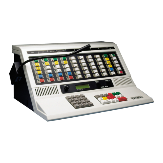
Introduction Identification of Console Models Figure 4: Integrator RD Workstation Figure 5: Model 4118 Dispatch Console 025-9533Y... - Page 21 System Overview Figure 6: Model 4115B Console Expander Figure 7: Model 4018 Desktop Console Figure 8: Model 4217B Audio Panel...
-
Page 22: Installation Sequence
The sections in this manual are prepared in a sequence in which the system should be installed. If you need further assistance, please contact Zetron at http://www.zetron.com. Planning Installation begins with planning the system layout. - Page 23 Testing When planning, mounting, configuring, and wiring have been completed, the system is ready for its first installed test. The system has been tested at the Zetron factory; this preliminary system check verifies proper configuration and wiring. Level Setting The last step is to adjust the audio levels in the system.
-
Page 24: Manuals
Introduction Manuals The manuals identified in the following table may be necessary to install and operate the Model 4048/4020 CCE. Table 1: Series 4000 System Manuals Primary Manuals Title Part # Description Series 4000 Communication Control 025-9533 Describes how to configure and install the Model System Installation and Configuration 4048 and Model 4020 Common Control Equipment, (this manual) -
Page 25: Specifications
Specifications Specifications Physical Specifications Model 4048 Common Control Equipment Channel Card Cage 15.75 x 19 x 9.75 inches Console Card Cage 17.5 x 19 x 9.75 inches Power Supply 3.5 x 19 x 9.75 inches Model 4020 Common Control Equipment Common Card Cage 17.5 x 19 x 9.75 inches Audio Consoles... -
Page 26: Receive Electrical Specifications
Introduction Receive Electrical Specifications Input Impedance 600 or 10 k (4-wire)/3500 ohm (2-wire) Line Balance 66 dB at 1000 Hz Rx Sensitivity -30 to -28 dBm max at knee of compression; adjustable Freq. Response -3 to +1 dB from 300-3400 Hz (except GT notch) Compression Input level increase of 30 dB above the knee of compression causes <3 dB output increase... -
Page 27: Other Electrical Specifications
Specifications Other Electrical Specifications Radio Control Local (E&M), Tone Remote, DC Remote Radio Channels 2-wire simplex/half-duplex or 4-wire half/full duplex DC Control Operable up to 8 k loop resistance. Current programmable 15 mA max in 2.5 mA increments. Accuracy +/-0.25 mA Tone Control 15 standard tones supported, programmable (no trimmer adjustment) 650-2050 Hz. - Page 28 Introduction 025-9533Y...
-
Page 29: Common Control Equipment Installation
Common Control Equipment Installation In this chapter: • Model 4048 Mounting on page 30 • Model 4048 CCE Set Up on page 31 • Model 4020 CCE Set Up on page 37 • System Grounding on page 39 • Configuring the System Traffic Card (STC) on page 41 •... -
Page 30: Model 4048 Mounting
Common Control Equipment Installation between the CCE and the dispatch consoles should be less than 2000 feet, unless modems or optics are used for the data paths. Short Haul Modems (P/N 950-9222) are required beyond 2000 feet and up to 1 mile. The VoIP Console Gateway (P/N 905-0265) is required for distances longer than a mile. -
Page 31: Cce Channel Cardcage
The Model 4048 CCE has card slots in each cardcage, designated 1-18, from left to right. Since the system is assembled and tested at the Zetron factory, you will also find circuit cards already plugged into some slots. Several types of circuit card may be used in the cabinet. -
Page 32: Model 4048 Power Supply
Power Supply Connections The two following tables give the pinouts for the two different types of output cable on a Model 4048 power supply. The connector part numbers listed in each figure are Zetron part numbers and are listed for reference only. - Page 33 Model 4048 CCE Set Up Table 4: Console Cardcage Power cable Color Purpose Purple Not Used White Error Signal Connector Part Numbers: Yellow +12 V • Connector: 401-0116 Blue +5 V • Hood: 401-0117 Brown Ground Black Ground Black Ground Please check both connector Brown Ground...
- Page 34 Common Control Equipment Installation Adding DC Backup To use 12 V as a backup to the AC supply 1. Measure the voltage at the BATT terminal (on the front of the supply) relative to GND. 2. Measure the voltage at the +12V terminal. 3.
- Page 35 Model 4048 CCE Set Up Dual Power Supplies To adjust a system with two power supplies Note Power supply adjustment must be performed on one power supply at a time, with the other power supply disconnected from its power source.
-
Page 36: Console Cardcage
Common Control Equipment Installation Console Cardcage The Console Cardcage includes connectors for ribbon cables that interconnect the console cardcage with each of the two channel cardcages, which will be mounted below. Several ribbon cables are delivered with the system for this purpose. Figure 10 identifies these cables and their associated connector locations. -
Page 37: Channel Cardcage
Model 4020 CCE Set Up Channel Cardcage If your system includes Auxiliary I/O (AUX I/O) capability, the AUX I/O adapter plate that accommodates the cable connectors has been installed at the factory. Model 4020 CCE Set Up The Model 4020 (Part # 901-9582) is a single rackmount cardcage that holds up to 19 circuit cards. - Page 38 Common Control Equipment Installation A pair of Model 4048 Power Supplies may also be used. To install or replace the internal Model 4020 Modular Power Supply 1. If the supply was not previously installed, a cover plate will have to be removed from the rear of the Model 4020.
-
Page 39: System Grounding
The length of the runs should be minimized. Securely connect a grounding wire to the case of each unit, making sure metal connection is made (no paint or oxidation layer). Most Zetron equipment provides a grounding stud. If the console includes a computer, connect an individual grounding wire to the computer chassis. - Page 40 EARTH GROUND Jack #0 AWG or Larger Do not connect signal ground to the central “star” ground. The conditioning and reference of the signal grounds is controlled inside the Zetron equipment. The system will be more susceptible to noise interference. 025-9533Y...
-
Page 41: Configuring The System Traffic Card (Stc)
Configuring the System Traffic Card (STC) Configuring the System Traffic Card (STC) The system can have either one or two STC cards. A second card is used to improve system reliability. If a fault occurs in the STC card that has command of the system, the operation will revert to the secondary STC, and system operation will not be affected. -
Page 42: Jumpers
Common Control Equipment Installation Switches G and H are for factory use only. Both switches should be set to “OFF”. Jumpers There are three two-position jumpers on the card: JP1, JP2, and JP3. These jumpers should not require adjustment. Their function is described as follows. Configuring Console Cards The first step in configuring your CICs is to label each card with the name of the associated console. - Page 43 The CIC-to-Console data rate is specified by the three switches labeled 19.2K, 9600, and 1200. Only one of these switches should be switched “ON”. The default is 9600. The 19.2K switch is not currently used. The 1200 switch should be used with Zetron long haul modems for remote console installations.
-
Page 44: Cic Jumpers
Common Control Equipment Installation The CIC Mode switches are used for engineering diagnostics. The position of these switches does not affect console operation. Switch Function Reset on Backplane Error Engineering Service Port Rate Engineering Service Port Rate Engineering Service Port Rate Spare Engineering Service Port Data Rate CIC Jumpers... -
Page 45: Patch Card Jumpers
Connector Identification Switch Function [Factory Default] Select Alternate Program Boot (Engineering use only) [OFF] Disable Reset on Fault [OFF] Spare Spare Spare Spare Spare Spare Model 4020 or Switch Function (Factory Default) Model 4048 Enable first 8 patch circuits Enable second 8 patch circuits Per order Enable third 8 patch circuits Per Order... - Page 46 Common Control Equipment Installation Table 8: Model 4048 Console Cardcage Connector Identification Connector Connector Destination and/or Purpose Consoles 1 & 2 Consoles 3 & 4 Consoles 5 & 6 Consoles 7 & 8 Consoles 9 & 10 Consoles 11 & 12 Consoles 13 &...
- Page 47 Connector Identification Table 10: Model 4048 Channel Cardcage #2 Connector Identification Connector Connector Destination and/or Purpose Radio Channels 37-40 Radio Channels 41-44 Radio Channels 45-48 J4, J5, J6 AUX I/O outputs J7, J8, J9, J12 (Not used) Table 11: Model 4020 Console Cardcage Connector Identification Connector Connector Destination and/or Purpose Consoles 1 &...
-
Page 48: Configuring Channel Cards
You can configure each Dual Channel Card (DCC) installed into the channel cardcage to meet the requirements of the channel pairs. Card configuration is typically not performed at the Zetron factory, so even if the system has been assembled and programmed by Zetron, you need to configure the cards. -
Page 49: Line Termination
Configuring Channel Cards Option Selection Device Motorola/GE Current Conversion Switch (DC Control Only) Figure 12: Dual Channel Card Configuration Switches Using a Tone or DC Card for Local Control CONFIG ON OFF There may be times when it is desirable to use a tone or DC channel card to control a local control channel, for example when interfacing to a telephone channel or intercom. -
Page 50: Channel Cross-Mute
14). This is useful to prevent audio feedback between two channels on the same frequency at the same console, or to prevent audio feedback between the Zetron consoles and other consoles present in the same room. Each DCC has the same option. -
Page 51: Busy Transmit Inhibit
Configuring Channel Cards operation. Switching between COR and VOX operation is a software configuration item. Tone/Local Software Configuration on page 54. There is also an Enhanced Call Detection mode available that provides a more precise call detection method, provided certain requirements are met. For more information, see Enhanced Call Detection Mode on page 62. -
Page 52: High Level Guard Tone Duration
Common Control Equipment Installation Table 16: Dual Channel Card, Duplex Switch Channel A Duplex Switch Position Full Duplex Operation “FD” (switch 8) On Simplex Operation “FD” (switch 8) Off* Channel B Duplex Switch Position Full Duplex Operation “FD” (switch 4) On Simplex Operation “FD”... -
Page 53: Low Level Guard Tone Amplitude
Configuring Channel Cards Low Level Guard Tone Amplitude The Low Level Guard Tone Amplitude (LLGT) for tone channels defaults to -30 dB but is a software configuration item for the Universal Tone/Local DCC (P/N 950-9819 and 950- 9820). The LLGT can be changed from -20 to -34 dB in 2 dB increments as described in the Universal Tone/Local DCC Software section. -
Page 54: Tone/Local Software Configuration
The basic operating mode and optional features of the Universal and Tone/Local DCCs are configured through the serial port. This requires an ASCII terminal or a computer running a terminal emulation program and the Zetron Serial Interface Cable (Part # 709-7452). The following features may be enabled using the channel card configuration interface: •... - Page 55 Configuring Channel Cards • Channel Transmit Delay Note Since the final step in any configuration process results in a card reset, make sure both channels are inactive before making any configuration changes. To start the configuration software 1. Switch all SW4 switches OFF. 2.
-
Page 56: Channel Configuration
Common Control Equipment Installation Channel Configuration To configure the operating mode of each channel 1. From the main menu, press C. 2. Press A or B to configure Channel A or Channel B. The following menu is displayed: Define,Review,Store,Init,Log,: •... -
Page 57
Configuring Channel Cards a. Press F to define a Guard Tone frequency. A:2100,B:2175,C:2300,D:2325,E:2600,F:2800,G:2970,
: b. Press D to define a custom High-Level duration GT. enter ’10' to ’79' (duration in 10 ms units), : c. Press L to define a custom Low-Level GT amplitude (dB relative to High Level Guard Tone). - Page 58 Common Control Equipment Installation AGC Peak Detector Decay Setting a higher decay time will cause the locked AGC gain to be lower when the audio input level drops towards zero. This will reduce the background noise level when the channel is idle but slightly reduce the AGC response time. ...
- Page 59 14-bit decode GE-Star #3 14-bit decode ID Star #1 14-bit decode NYSP See note. Note GE-Star NYSP (format K) is a special format reserved for NYSP. Using this format requires a separate Zetron software license. 4. Backspace to the GE-Star menu.
-
Page 60
Common Control Equipment Installation 5. Press E to define the desired Emergency ANI behavior from the following menu: All,Only_1st,Timed,
: Option Result All emergency ANI numbers are reported Only the first occurrence of an emergency ANI number is reported. Subsequent repeats are ignored until a different ANI number is received. -
Page 61
Configuring Channel Cards Review and Save Channel Configuration To make the configuration permanent and active 1. Backspace until the following menu is displayed: Define,Review,Store,Init,
: 2. Press R to review and verify the new configuration. Then press S. Options Configuration ... -
Page 62: Enhanced Call Detection Mode
The DSP trace output feature is for factory use only. It should only be used when prompted to do so by Zetron Technical Support. Normally this feature should be turned off. It is configured via the diagnostic port as follows: uDCC88 v2.79 ------... - Page 63 Configuring Channel Cards To configure Enhanced Call Detection mode 1. Configure the Universal Dual Channel Card (UDCC). Note Step 1 applies to both VOX+COR and VOX+LLGT detection methods. a. Connect to the UDCC from a maintenance PC using a serial cable and terminal software set to 19200-8-N-1-NONE.
- Page 64 Common Control Equipment Installation 3. Configure the iRIM for LLGT. Note Step 3 only applies to the VOX+LLGT method of detection. For VOX+COR, skip to Step Configuring the iRIM requires that you have a working network connection from a maintenance PC to an installed iRIM. If you do not, see Intelligent Radio Interface Module for Kenwood Radios (P/N 025-9520) for connection information.
-
Page 65: Led Error Display
Wiring to the Channels LED Error Display If a critical error occurs during reset or power-up of a Universal or Tone/Local DCC, its front panel ERROR LED illuminates. Certain other LEDs flash to indicate which error occurred, as shown in Table 19. - Page 66 Common Control Equipment Installation Table 20 shows the channel allocations by slot designator and plug designator for the Model 4048. Table 21 shows the channel allocations by slot designator and plug designator for the Model 4020. Note This section describes the signal connections for conventional channels.
- Page 67 Wiring to the Channels Each 50-conductor plug carries four radio channels, referred to as Channel A, B, C and D. Each channel includes twelve signals. Figure 13 is a schematic of conventional signals, equivalent circuits, and the plug connections on which they are found. Table 22 is a summary of the signals found on each channel plug.
- Page 68 Common Control Equipment Installation Table 22: 50-Conductor Plug, Channel Signal Summary Signal Wire Color Connector Wire Color* Signal Chan A. PTT- Wht/Blu Blu/Wht Chan A. PTT+ Chan A. COR- Wht/Org Org/Wht Chan A. COR+ Ground Wht/Grn Grn/Wht Chan A. Aux Output Chan A.
- Page 69 Wiring to the Channels Figure 14: Split 50 66m Type Punch-down (P/N 950-9351) for Signals for Eight Channels FOUR CHANNELS ADJACENT FOUR CHANNELS Chan. A PTT - Chan. A PTT - Chan. A PTT + Chan. A PTT + Chan. A COR - Chan.
- Page 70 Common Control Equipment Installation Figure 15: Protected Punch-down Block for Radio Channels MODEL 4048 OUTSIDE SYSTEM LINES SECONDARY PRIMARY PROTECTION PROTECTION OVERALL CONFIGURATION INCOMING LINES GROUNDING BUS FOUR CHANNELS Punchdown Block Chan A PTT - í Chan A PTT + P/N 950-9351 Chan A COR - Chan A COR +...
-
Page 71: Push-To-Talk
Wiring to the Channels Push-to-Talk +/- The dry contacts across these two signals close whenever the channel is transmitting. This may be used for a single function, local transmitter keying, or E&M signaling. The contacts will handle 1A at 48V. While the PTT contacts are closed, the “XMIT” indicator on the channel card is on. -
Page 72: Cross-Busy Input/Output
Common Control Equipment Installation receive sensitivity may be adjusted to -30 dBm using the “4W RX” adjustment on the channel card edge. Warning! Do not parallel a DC Dual Channel Card with a Tone Control STOP Dual Channel Card. The interface could be damaged. Cross-Busy Input/Output This input/output pair is used for cross-busy handshaking for multiple parallel control point arbitration. -
Page 73: Electrical Specifications
The instructions in this section are somewhat generic. If you are configuring an Aux I/O Card specifically for use with a Zetron Intercom Interface, see the Series 4000 and Model 4010 Intercom Interface Product Manual (P/N 025-9331 rev C or newer). That manual provides installation, configuration, and programming instructions that are much more specific to that task. -
Page 74: Configuring The Auxiliary Input/Output Card
Common Control Equipment Installation Power Line 60 Hz Synchronization (Use a 110/220 Step-Down Transformer) Input Voltage: 9 or 12V AC with 50-60 Hz/sec Configuring the Auxiliary Input/Output Card The only configurable items on the Aux I/O Card are the card’s address and 50/60-Hz timing selection. - Page 75 Auxiliary I/O Card Installation (Optional) Table 25: Auxiliary Output System-To-Card Conversion Card Address Output...
- Page 76 Common Control Equipment Installation Table 26: Auxiliary Input System-To-Card Conversion Card Address Card Input *37 *38 *39 *40 * Card Inputs 33-40 are optically isolated Input for time synchronization. 025-9533Y...
-
Page 77: Wiring To The Auxiliary Input/Output Card
Auxiliary I/O Card Installation (Optional) Wiring to the Auxiliary Input/Output Card Each Aux I/O Card uses two connectors inside the CCE. The card’s outputs use half of one of the 50-conductor plugs, depending on which channel slot has the card inserted into it. The card’s inputs use a special ribbon cable, with a red stripe on the edge, that is supplied with the card. - Page 78 Common Control Equipment Installation Figure 16: Model 4020 50-Conductor Plug Mounting 250-0105 Area of Detail Aux I/O outputs Table 27 Aux I/O inputs Pin #1 Stripe Should be on left side when facing unit. Port cover is removed whenever Aux. I/O Card is installed.
- Page 79 Auxiliary I/O Card Installation (Optional) Figure 17: Model 4048 50-Conductor Plug Mounting Aux I/O inputs Area of Detail Aux I/O outputs Remove the bottom cover of the main Table 27 chassis while installing the Aux. I/O Card cable to make the job easier. 250-0030 + 220-0105 Move cover plate up when the cable is...
-
Page 80: Relay Output Connections
Common Control Equipment Installation Relay Output Connections The plug, at which the outputs from the Aux I/O Card may be found, is dependent on the slot into which it is plugged. Table 27 will help you locate the proper plug. Table 28 identifies the pin number of the plug on which to find the desired output signals. -
Page 81: Auxiliary Relay Output Jumper Setting
Auxiliary I/O Card Installation (Optional) Table 28: Auxiliary Outputs, 50-Conductor Plugs — Top Half of Punch Block — Output Relay Signal Wire Color Signal Wire Color Blue/White White/Blue Orange/White White/Orange Green/Orange White/Green Brown/White White/Brown Slate/White White/Slate Blue/Red Red/Blue Orange/Red Red/Orange Red/Green Red/Green Brown/Red... - Page 82 Common Control Equipment Installation Figure 18: A Typical Relay Diagram RLY n RLYn A Left Jum per Right Jum per RLYn B Figure 19: Jumper Pairs as Viewed on PC Board Near Relays Left Jumper Right Jumper By arranging these jumpers each relay output can be configured as shown in Table 29.
-
Page 83: Input And Timing Input Connections
Auxiliary I/O Card Installation (Optional) Table 29: Relay Jumper Configuration Relay Contact Left Jumper Right Jumper Configuration Relay off, A & B signals open Relay on, A & B signals connected Relay off, A & B signals connected Relay on, A & B signals open Relay off, A signal open, B signal grounded Relay on, A... - Page 84 Common Control Equipment Installation two signals: a current input (+) and output (-). Table 31 identifies the pin number of the plug on which to find the desired input signals. Table 31: Auxiliary Inputs, Special 50-conductor Plug Punch Punch Input Wire Color Input Wire Color...
-
Page 85: Standard Input Connections
Auxiliary I/O Card Installation (Optional) Standard Input Connections By making the connections shown in Figure 20, the indicator on the operator console is active when the switch is closed. The input circuitry is active low and does not require 12 VDC applied externally. -
Page 86: Wiring To The Consoles
Common Control Equipment Installation Wiring to the Consoles Each Console Interface Card (CIC) interfaces one dispatch console to the system. Each console is referred to by console number 1-16 for the Model 4048 and 1-6 for the Model 4020. The console that a CIC is controlling is determined by the card slot into which the console card is plugged. -
Page 87: Wire Distribution
Wiring to the Consoles Wire Distribution The connection between the CCE and the consoles is made by connecting the 50- conductor plugs to punch-down blocks, and then through normal twisted-pair distribution to modular duplex wall jacks near the console. From the wall jacks, two half-twist, 6- conductor modular telephone cables connect to the two modular jacks on the back of the dispatch console control panel. - Page 88 Common Control Equipment Installation Figure 22: Console Duplex Wall Jacks 025-9533Y...
-
Page 89: Console Signal Descriptions
Wiring to the Consoles Figure 23: Protected Punch-down Blocks for Consoles INCOMING LINES GROUNDING BUS FOUR CHANNELS Punchdown Block í P/N 950-9351 MON B + MON B - MON A - MON A + IC Data - IC Data + INCOMING LINES TO CCE CI Data -... - Page 90 Common Control Equipment Installation Unselect Voice +/- (Uns +/-) This balanced pair of audio signals from the CIC provides the dispatch console with a nominal 0 dBm output of the unselected channel’s receive audio. It is important that these two signals are physically paired (twisted) for most of the wiring run. Microphone Voice +/- (Mic +/-) This balanced pair of audio signals from the dispatch console provides the CIC with a nominal 0 dBm output of the microphone’s transmit audio.
-
Page 91: Series 4000 Phone Coupler (Optional)
4000 Communication Control System in conjunction with a Zetron IntegratorRD workstation or Zetron Model 4018 or 4118 button console. It can also be used with the standalone Zetron Model 4010 Radio Dispatch console if more than two phone lines are needed. -
Page 92: Installation
Common Control Equipment Installation Tx Audio -40 to +6 dBm, HI/LO selector, 1 k output impedance Rx Audio -40 to +10 dBm, HI/LO selector, 50 k input impedance, 25 mV to 6 Vpp Front Panel Power LED Indicates 12 VDC power applied Ring LED Blinks when an incoming call is detected Supervision LED... - Page 93 Series 4000 Phone Coupler (Optional) Coupler Wiring Connection to the console is made using a type 66 punch-down block (refer to Figure 25 on page 97). The following table indicates signal names, wire colors, and exact pin location relative to the phone coupler product's connector.
-
Page 94: Testing
Common Control Equipment Installation Other useful functions are: On All Consoles Function Volume Adjust Allow receive level to be set from the console. Mute Allow the phone channel to be muted by the console operator. Instant Transmit Allow transmission on the phone channel without “selecting” the channel. Patch Allow the phone channel to be “patched”... - Page 95 Series 4000 Phone Coupler (Optional) 3. Hybrid Adjustment Note Tests 1 and 2 are performed at the factory. These two gain settings should never again need to be adjusted. Test 3 needs to be performed during installation. Each test runs for up to 3 minutes. During that time, if the Connect button is pressed again, the next test will commence.
- Page 96 Common Control Equipment Installation Setting Initial Receive Level Note This value is set at the factory and should never need to be adjusted again. To perform the diagnostic tests, it is necessary to do a rough setup of the Receive Gain sensitivity.
- Page 97 Series 4000 Phone Coupler (Optional) Test 2: Repeat Audio Gain Note This test is performed at the factory and should never need to be done again. 1. Advance to Test 2 by pressing the Connect button. Verify that Test 2 is running: you should see two -second blinks of the Ring LED every 3 seconds.
- Page 98 Common Control Equipment Installation Figure 25: Split 50, 66M-type punch-down blocks (P/N 950-9351) Connections to Channels A and C Connections to Channels B and D •==• 26 Chan A. PTT – •==• 26 Chan A. PTT – Channel A Channel B •==•...
- Page 99 Series 4000 Phone Coupler (Optional) Jumper Switch Settings Table 37: Jumper switch settings Switch Description Settings Receive gain A = LO * B = HI Not installed Source for Off Hook signal A = Internal B = External * Selects decode polarity for the external tone decoder A = Valid Low B = Valid High * Selects proper de-emphasis network for receive audio A = Speaker audio *...
-
Page 100: Wiring To The Logging Recorder
Common Control Equipment Installation Wiring to the Logging Recorder Each channel provides a logging recorder audio output which is the summation of the transmit and receive audio for the channel. The outputs are single-ended (not balanced), DC blocked, and provide about 0 dBm (0.75 Vrms into 600). All recorder outputs are avail-able on one or two 50-conductor plugs, J12 on channel cardcage #1 for channels 1- 24 and J9 on the console cardcage #2 for Channels 25-48 (see Table... - Page 101 Wiring to the Logging Recorder * First color is main color and the second color is stripe. Wht = white, Red = red, Blk = black, Yel = yellow, Vio = violet, Blu = blue, Org = orange, Grn = green Brn = brown, Slt = slate.
-
Page 102: Wiring To The Service Ports
Common Control Equipment Installation Wiring to the Service Ports The CCE provides several 9-pin “D-type” female receptacles, J10 – J13, for connecting to service ports. The connectors are located on the top right-hand side of the back of the console cardcage (see Table 41 Table 42). -
Page 103: Wiring To The Alarm Circuit
Wiring to the Alarm Circuit Wiring to the Alarm Circuit The alarm circuitry of the CCE can be used to give an external indication of both external and internal events. Alarm sources include an external contact monitor, a monitor of circuit card “ERROR”... -
Page 104: Modem Configuration
Common Control Equipment Installation Table 45: Model 4048 Common Control Alarm Connector Signals Signal J16-1 (bottom) Ground J16-2 Alarm Input (active when shorted to ground) J16-3 Ground J16-4 Alarm Output Contact, Normally Closed J16-5 Alarm Output Contact, Common J16-6 (top) Alarm Output Contact, Normally Open The contact ratings for the alarm relay are: Initial Contact Resistance, Max. -
Page 105: Modem And Service Port Operation
Operation Once connected, press Enter. A prompt similar to the following should be displayed. ( 2 Oct 1998 08:23:09.66) Zetron M4048 Service Port (STC1 rev 01.05E) Enter command (? = help): The version information (in this case “STC1 rev 1.05E”) shows which STC (1 or 2) is in control of the system and the software version of that STC. - Page 106 H) History log functions P) Port configuration menu O) ANI display option G) Goodbye (log out) ( 2 Oct 1998 08:23:09.66) Zetron M4048 Service Port (STC1 rev 01.05E) Enter command (? = help): The $Version line displays the current STC code version. Note The Login and Goodbye options are not used in normal operation.
- Page 107 Modem and Service Port Operation Figure 26: Example History File 23 Sep 1998 08:49:00.42 ( 112) This is STC1, in control of the system 08:49:00.00 ( 113) This is STC1, NOT in control of the system 08:48:59.32 ( 103) Clock source = Console 22 Sept 1998 00:00:13.30 ( 94) Console...
-
Page 108
Radio Management RADIO MANAGEMENT ( 2 Oct 1998 08:24:11.74) Zetron M4048 Service Port (STC1 rev 01.05E) Enter command (? = help): To change a port setting, type P
and press Enter, where is L, B, or R. (Select the port that you want to change). -
Page 109: Logger Port Function
Logger Port Function Logger Port Function The Model 4048 and Model 4020 systems diagnostics log (output of the Logger port) shows system configuration changes (slots going active or inactive) and errors. This is the same output as the history log with Card Configuration reports included. ANI Signaling Automatic Number Identification (ANI) signals are voice band data signals that are transmitted from a mobile or portable radio to the consoles. - Page 110 Common Control Equipment Installation 025-9533Y...
-
Page 111: Wireless Interface Options
025-9566 MAP27 Wireless Interface Option Introduction The Zetron Series 4000 MAP27 Wireless Interface Option is designed to interface a Model 4217B or Model 4219 console to a MAP27 radio. Supported radios include: • Tait T2030, T2035, and T2040 • Tait TM-8255 series •... - Page 112 (radio specific ) The MAP27 Wireless Interface Option can be added to existing IntegratorRD console systems with the addition of the MAP27 Wireless Control Card, the Zetron MAP27 Wireless Interface Module, software upgrades to the Console Interface Card, and the console itself.
-
Page 113: Required Equipment And Recommended Documentation
• IntegratorRD console with Model 4217B or 4219 • Punchdown block (P/N 950-9351) and wire • Zetron MAP27 Wireless Interface Option including: • The proper Wireless Interface Module for your radio • The proper Wireless Interface Module cable for your radio •... -
Page 114: Installation
Wireless Interface Options Installation MAP27 Dual Channel Control Card Configuration The MAP27 Wireless Control Card must be configured before installing it in the Series 4000 system. The card has four switches for each of the two channels. The switches are located at the bottom of the legend plate under the label “Config.”... - Page 115 MAP27 Wireless Interface Option Installation Connections CCE Interconnects Connection to each channel of the MAP27 Wireless Control Card in the CCE rack is made through a punchdown block (see Table Table Figure 28, and Figure 29). Table 48: Punchdown Block (P/N 950-9351) Connections for GM1200E or Tait radios Punchdown Signal Name 1A|1B|2A|2B...
- Page 116 Wireless Interface Options Table 50: Punchdown Block (P/N 950-9351) Connections for GM1200 radio Punchdown Signal Name 1A|1B|2A|2B ConnectorP2 1| 7|13|19 TX Data + TX Data - 26|32|38|44 RX Data + 2| 8|14|20 RX Data - 27|33|39|45 Busy Out + 3| 9|15|21 28|34|40|46 Busy Out - Busy In +...
- Page 117 MAP27 Wireless Interface Option Figure 28: Punchdown Block (P/N 950-9351) Connections for GM1200E or Tait radios Chan 1A. TX Data + •====• Chan 1A. TX Data + Chan 1A. TX Data - •====• Chan 1A. TX Data - Chan 1A. RX Data + •====•...
- Page 118 Wireless Interface Options Figure 29: Punchdown Block Connections (P/N 950-9351) for M427 Dispatcher Port Chan 1A. TX Data + •====• Chan 1A. TX Data + Chan 1A. TX Data - •====• Chan 1A. TX Data - Chan 1A. RX Data + •====•...
- Page 119 MAP27 Wireless Interface Option Figure 30: Punchdown Block Connections (P/N 950-9351) for GM1200 radio Chan 1A. TX Data - •====• 26 Chan 1A. TX Data - Chan 1A. TX Data + •====• Chan 1A. TX Data + Chan 1A. RX Data - •====•...
- Page 120 Tait T2030, T2035, T2040 (Equipped With T2000-60 Dual Port UART) Connection from the interface module 10-pin connector to the Tait radio 15-pin connector is made with Zetron cable P/N 709-7534 supplied with the interface module. The connections are listed in...
- Page 121 MAP27 Wireless Interface Option Motorola GM1200 Connection from the interface module 10-pin connector to the MAP radio 25-pin connector is made with the cable (P/N 709-7477) supplied with the interface module. The connections are listed in Table Table 53: Interface Module Connections (GM1200 radio) GM1200 Radio WIM Connector P1 DB-25 Connector...
-
Page 122: Radio Programming
Wireless Interface Options M427 Dispatcher Port Connection from the interface module 10-pin connector to an M427 Dispatcher Port (1 of 4 available) is made with the cable supplied with the interface module (Zetron P/N 709- 7554). The connections are listed in Table... - Page 123 Tait radio programming software: Note Many radio settings are not mentioned in the following procedure; either those settings don’t apply to the Zetron Console application, or they are dependent on the individual user’s trunking environment and personal preferences.
- Page 124 “Group Callable” to TRUE. 5. Under Edit, MPT Personality, Text Related Status: These entries apply to the radio itself but will not be translated to the Zetron console. The aliases for the status messages that appear at the console are...
- Page 125 MAP27 Wireless Interface Option programmed in RDPS. If desired, the status aliases for the radio can be programmed to match the RDPS file. 6. Under Edit, MPT Personality, MAP27 – Data Calls: Note ENABLED is a checked box, DISABLED is an unchecked box. •...
- Page 126 To configure the Model 427, use the Zetron M827Base for Windows programming software as described in the following procedures. First the Zetron M427 dispatcher port must be programmed to support the interface to a Zetron console. ...
- Page 127 MAP27 Wireless Interface Option Next, add a dispatcher assigned to the associated Map27 port and set the privileges and associated groups for this user. To configure the Dispatcher Units 1. Start the M827BASE for Windows application. 2. Navigate to Fleet Configuration Editor, Edit, Dispatcher Units Editor. 3.
-
Page 128: Map27 Audio Level Settings
Wireless Interface Options Next, add a Map27 telephone port for the connected M4217 dispatcher. To configure the Telco Port 1. Start the M827BASE for Windows application. 2. Navigate to Site Configuration Editor, Edit, Telco Ports Editor. 3. Define the Site Selection. 4. - Page 129 Required Tools • A PC or laptop with a serial port and Windows XP • Zetron M827Base for Windows (version 3.60.146 or later) • Serial cable (straight-through serial extension cable) • Small flat bladed screw driver to adjust gain pots on front of MAP27 card (0.12”...
-
Page 130: Operation
1. Connect the COM1 serial port on the PC or laptop to the M427 front panel serial port using a straight cable. 2. Start the Zetron utility program M827Base. 3. Click FILE, CONNECT, SITE LIST, CONNECT in order to select the Communications Utility and connect to the M427 being setup. - Page 131 MAP27 Wireless Interface Option • Status ID aliases and button definitions Entering Status ID Definitions on page 297 • Talkgroup aliases (for display of groups) Entering Talk Group Definitions on page 298 • SST Text button definitions Entering MAP27 Short Status Text Definitions on page 301 •...
-
Page 132: Harris M7100 Wireless Interface Option
The Harris Wireless Interface Option consists of a Dual Channel (Orion) Wireless Control Card (P/N 950-9867), which can interface with two radios. Each radio needs one Zetron Orion Wireless Interface Module (P/N 950-9868). The Dual Channel Card is installed in the Series 4000 Common Control Equipment (CCE) rack. -
Page 133: Recommendations
Harris M7100 Wireless Interface Option Both channels on the Harris Dual Channel Wireless Control Card must be Harris interface channels. Recommendations The following recommendations are made concerning overall system design: Each of the radios should operate from its own 12VDC power supply. For each radio in the system to achieve proper performance and stability, it is important that adequate separation be provided among all of the radio antennas for the system. - Page 134 1. Use a terminal set for 19200, 8, N, 1 (with no flow control) to connect to the monitoring port on the front panel using the Zetron cable P/N 709-7452. 2. Once connected, press Esc to get the following menu (the version number may vary, and your options may vary based on your version): Orion v1.24.01, 2013-MAR-24...
-
Page 135
A:20%, B:40%, C:60%, D:80%, E:100%,
: # Zetron recommends 100% (E). 10. The Vox options (default is enabled): Log,Volume,voX enable,vox Threshold,vox Delay, : X Disable,Enable, : # Zetron recommends VOX enabled (E) unless you have an older firmware version (see note above). -
Page 136: Installation Connections
Log,Volume,voX enable,vox Threshold,vox Delay,: T A:-18dB, B:-20dB, C:-22, D:-24, E:-26, F:-28, G:-30, H:-32, : # Zetron recommends -18dB (A) for the initial setting. The setting can be adjusted later if needed, during audio level adjustment procedures. 12. The Vox Delay options (default is 0.5sec): Log,Volume,voX enable,vox Threshold,vox Delay, ... - Page 137 Harris M7100 Wireless Interface Option Table 57: Punchdown Block (P/N 950-9351) Connections for Orion Dual Channel Card Punchdown Signal Name Connector P2 TX Data + TX Data - RX Data + RX Data - Busy Out + Busy Out - Busy In + Busy In - TX Audio +...
- Page 138 Wireless Interface Options Table 58: Punchdown Block (P/N 950-9351) Connections ---26 Chan 1A. TX Data + Chan 1A. TX Data + ---01 Chan 1A. TX Data - Chan 1A. TX Data - Chan 1A. RX Data + ---27 Chan 1A. RX Data + Chan 1A.
-
Page 139: Adjusting Levels
4-wire audio from the Harris Dual Channel Wireless Control Card to the radio. Connection from the interface module 10-pin connector to the radio 37-pin connector is made with the 20-foot cable supplied with the interface module (Zetron P/N 709-7437). The connections are listed in... - Page 140 1. Connect a programming cable between the rear of the radio and a serial port on the programming PC. 2. Leave Zetron common control cable disconnected. 3. On the PC, start up the Harris ProGrammer software. Power up the radio control head to get into programming mode.
- Page 141 6. Under Network Options, enable Dual Control. Accept all the default selections under Dual Control. Note If the radio currently connected to the Zetron CCE does not have a factory control head installed, it is not necessary to program the radios for dual control head operation.
-
Page 142: Operation
Also, see above instructions for basic flow of programming. The factory attached control head should be programmed as CUB (control unit B) while the Zetron equipment should be programmed into the radio as being CUA (control unit A). Upon programming completion the factory attached control head should read *DUAL*. - Page 143 Harris M7100 Wireless Interface Option Video Console Operation Refer to Series 4000 Communication Control System Operation (P/N 025-9535) for general operation. The following describes the features of the Orion interface. There are two display lines within each channel control module to indicate the mode and state of the attached Orion radio (see Figure 32).
-
Page 144: Harris M7300 Wireless Interface Option
259. Harris M7300 Wireless Interface Option Overview This kit is used to connect Harris M7300 series radios to a Zetron Series 4000 system and also includes instructions on upgrading the S4000 Dual Channel card firmware Assembly Level Part Numbers •... -
Page 145: Radio Setup
Radio Setup A Harris radio personality must be programmed to support the interface to a Zetron IntegratorRD console. To take advantage of the console ID alias capability, no LID information (or aliases) should be programmed into the radio (no individual call IDs should be programmed). - Page 146 Keycode = Ext PTT Control Unit = A 5. Initiate programming of radio. 6. Upon completion of programming, power down the radio by removing power 7. Remove the programming cable and connect the radio to the Zetron control cables. 025-9533Y...
-
Page 147: Wireless Dual Channel Card Configuration
1. Use a terminal set for 19200, 8, N, 1 (with no flow control) to connect to the monitoring port on the front panel using the Zetron cable P/N 709-7452. 2. Once connected, press Esc to get the following menu (the version number may vary, and your options may vary based on your version): Harris M-Series V2.03.01 2013-Mar-20... -
Page 148
11. The Vox Threshold options: Log,Volume,voX enable,vox Threshold,vox Delay,
: T A:-18dB,B:-20dB,C:-22,D:-24,E:-26,F:-28,G:-30,H:-32, : # Zetron recommends -18dB (A) for the initial setting. The setting can be adjusted later if needed, during audio level adjustment procedures. 12. The Vox Delay options (default is 0.5): Log,Volume,voX enable,vox Threshold,vox Delay, ... -
Page 149: Console Setup
Edit, Screen Buttons and Edit, Keyboard Layout menus are used to program the button and panel layouts (see Table 61). Some control buttons may be specific to the radio type. Harris M7300 radios operate on Zetron equipment in the same manner as Orion radios. - Page 150 Wireless Interface Options Table 61: Control Button Descriptions Button Function Description EDACS Clear Used to clear menu-selected functions. EDACS, I-Call, Next Scrolls through radio-programmed individual call users. Not supported by IntegratorRD. EDACS, I-Call, Prev Scrolls through radio-programmed individual call users. Not supported by IntegratorRD.
-
Page 151: Installation Connections
Harris M7300 Wireless Interface Option Installation Connections Figure 33: M7300 Radio Interface Kit connections. -
Page 152: Adjusting Levels
4-wire audio from the Harris Dual Channel Wireless Control Card to the radio. Connection from the interface module 10-pin connector to the radio 44-pin connector is made with the cable supplied with the interface module (Zetron P/N 709-8038). The connections are listed in... -
Page 153: Firmware Upgrade To The S4000 Dual Channel Card (950-1155) Option
1. Use a terminal set for 19200, 8, N, 1 (with no flow control) to connect to the monitoring port on the front panel using the Zetron cable P/N 709-7452. 2. Once connected, press Esc to get the following menu (the version number may vary, and your options may vary based on your version): Orion v2.00.0010, 2010-DEC-28... - Page 154 Wireless Interface Options 5. Re-Install the Dual Channel card and verify that the settings recorded in step 3 To configure the didn't change. If they did, reprogram as per instructions found in Dual Channel Wireless Control Card on page 147. 025-9533Y...
-
Page 155: Console Installation
Introduction Console Installation In this chapter: • Physical Placement, Desktop on page 156 • Physical Placement, Rackmount on page 157 • Power on page 157 • Programming Desktop and Rackmount Consoles on page 159 Configuring a Console • on page 160 Configuring Model 4115B Console Expander •... -
Page 156: Physical Placement, Desktop
The buttons on the console usually come from the factory with key tops engraved to match the function programmed by Zetron. If key function changes, additional engraved and clear key tops are provided. To remove a key top, pull it directly away from the front panel. -
Page 157: Physical Placement, Rackmount
The buttons on the console usually come from the factory with key tops engraved to match the function programmed for them by Zetron. If the function of a key changes, additional engraved and clear key tops are provided. To remove a key top, pull it directly away from the front panel. -
Page 158: Model 4018 Auxiliary Power
Console Installation A mating power connector is provided in the rack-mount panel’s accessory bag for users who prefer to use their own power supply. The power pin connections are listed in Table Table 64: Primary Power Pin Connections Signal Power- Open Power+ Power-... -
Page 159: Programming Desktop And Rackmount Consoles
Programming Desktop and Rackmount Consoles Installing the power cable strain relief Figure 47 on page 244. 1. Locate the end of the power cable (709-7938) that threads onto the PWR jack on the rear of the Model 4219. Plug this connector into the PWR jack and secure the locking nut 2. -
Page 160: Configuring A Console
Console Installation Configuring a Console A console has several jumper-selectable configuration options that show the various options and the normal factory setting. Table 65 shows the options and the default factory setting. Table 65: Model 4018 Jumper-Selectable Configuration Options OPTION NAME SETTING Select Speaker/Headset &... -
Page 161: Select/Unselect Audio Hookswitch Bypass
Configuring a Console Table 66: Model 4118, 4217B, and 4219 Jumper-Selectable Options Option Name Setting Select Speaker/Headset & Handset audio Select audio to select speaker JP10-A Select audio switch under software control JP10-B * Select audio to handset/headset interface JP10-C Unselect Speaker/Headset &... -
Page 162: Auxiliary Audio To Select Audio
Console Installation Auxiliary Audio to Select Audio The transmitted audio from the auxiliary audio input may be monitored at the position over the console speaker. This is useful when an external encoder is used, so that the operator can hear the encoder’s tones as they are being transmitted. Auxiliary Audio Input Impedance The auxiliary audio input is often used for connection to external encoders. -
Page 163: Common Control Data Rate
If an option code is not displayed, that option is set to the default condition. Some options require purchasing. To inquire about changing options to a Series 4000 console already in service, please contact Zetron’s Customer Service. Common Control Data Rate The rate of the data between the console and the CCE is selectable between high (9600 Baud) and low (1200 Baud). -
Page 164: Configuring Model 4115B Console Expander
Position Wiring the Dispatch Consoles This section describes how to wire accessory items to the console. The descriptions here are for generic accessories. For detailed information about Zetron accessories, refer to Accessory Installation on page 219. On the back of the dispatch console, there are connectors for connecting the console to the power, CCE, additional rackmount consoles, and various accessory items. -
Page 165: Voice And Data Jacks
If there is only a dispatch console at the position, the “Loop In” and “Loop Out” connectors must be connected. Headset/Handset Jackbox Connections The headset jack connector on the back of the console unit connects to Zetron headset and handset jackboxes or the Telephone Radio Headset Interface (TRHI). Refer to Accessory Installation on page 219 for a description of these functions. - Page 166 Console Installation Table 70: Auxiliary Audio Connector Pin-out Signal Busy Out Select Audio Out Aux Audio In Aux Audio Common Aux PTT In PTT Common D. mic Audio In+ D. mic Audio In- D. mic PTT In PTT Common Monitor SW In Mon Common Foot Switch FS Common...
-
Page 167: Microphone Push-To-Talk Implementation
Wiring the Dispatch Consoles receive audio. The Select Audio Out connection for the recorder output is shown in Table Microphone Push-To-Talk Implementation The console features two microphone ports. One port is for high-level electret element microphones, such as handsets or headsets. The other port accommodates low-level dynamic element microphones, such as desk mics or gooseneck mics. -
Page 168: Audio Source And Steering Note Summary
Console Installation routed to the console speaker. Various routing options for receive audio may be achieved by the placement of jumpers inside the console (see Table 65). The mic switch signal, when used in conjunction with the “electret PTT” signal, is used to re-route the microphone transmit audio between the electret mic port and the dynamic mic port. -
Page 169: Auxiliary Inputs
Wiring the Dispatch Consoles • “Soft” Transmit Keys There are four software-selectable audio steering options: • Always D Mic • Always E Mic • Mic switch (“Spare input #9”) steered • Hookswitch signal steered The possible external Audio source selections are listed in Table Table 72: Possible External Audio Source Selections CPSW... -
Page 170: Spare Outputs
Console Installation Table 73: Console Spare Input Connector Pin-out Signal Signal Input 1 Input 6 Input 2 Input 7 Input 3 Input 8 Input 4 Open Input 5 Ground Model 4018 uses connector P5, which is accessible through the wire access hole above the input power connector. - Page 171 Wiring the Dispatch Consoles The spare outputs may be programmed as momentary or toggle functions. If spare outputs 7 and 8 are not programmed, they will function as follows for Reverse Selective Calling mode for both M4x18 button consoles and IntegratorRD workstations: Spare Output 7 Turns on when an ANI is displayed on the console.
- Page 172 Console Installation 025-9533Y...
-
Page 173: System Check
Bringing the System Online System Check In this chapter: • Bringing the System Online on page 173 • On-Card Diagnostics on page 174 This chapter identifies the typical steps to follow when initially bringing the system on- line. The following procedures will help identify any wiring or configuration problems that may have occurred. -
Page 174: On-Card Diagnostics
System Check • The red “ERROR” LED may be illuminated but only on the Console Interface Cards (CICs). • No other ERROR LEDs should be illuminated. 5. Turn on the power to the console(s). The time/message display on the console may say “SEE.LOG”, but when cleared it should display a time (which may be incorrect). -
Page 175: System Traffic Card
76). If the system is equipped with a diagnostics printer, the printed log will usually detail the problem. If a problem with a card arises, note the condition of the card indicators and the diagnostic log printout before contacting Zetron. -
Page 176: Patch Card
System Check Table 76: On-Card Diagnostics Indicator Description PASS (green) Normally on. If this is off, the card has failed (or is failing) a diagnostic. Shorting the two pins of the “FAIL-RESET” jumper or pushing the “FAIL-RESET” push- button will turn this indicator back on. Depending on the detailed diagnostic on the system log, this card may or may not be in error. -
Page 177: Audio Level Adjustments
Required Equipment • Communication Service Monitor • Zetron S4000 Channel Monitor RS-232 Cable, 709-7452 • Digital volt meter equivalent to or better than a Fluke 189 True RMS (Digital) Multimeter, or an Oscilloscope with sufficient accuracy for the small audio levels... - Page 178 Audio Level Adjustments Table 79: System Level Adjustment Summary Adjustment Location Channel Receive Level Dual Channel Card Channel Transmit Level Dual Channel Card Channel Transmit Monitor Level Dual Channel Card Console Microphone Level (two) Console Console Auxiliary Input Level Console Console Line Loss Compensation Console Interface Card 025-9533Y...
- Page 179 Overview Figure 34: DCC Adjustments, Test Points, and Indicators 950/702-xxxx Dual Channel Card Part Number Channel B Channel B Test Points Transmit audio, before adjustment. 2.2Vpp max Not used AGC’d Receive audio. 2.2 Vpp max Pre-AGC Receive audio Signal Ground Channel B Level Adjustments Four-Wire Receive Level Two-Wire Receive Level/TX Monitor Level...
- Page 180 Audio Level Adjustments Figure 35: Model 4018 Control Board 025-9533Y...
-
Page 181: Dual Channel Card Audio Levels
Dual Channel Card Audio Levels Dual Channel Card Audio Levels Theory of Operation To adjust the audio levels it is necessary to understand the relationship between the levels of various types of audio signals used in the system. The voice signals will all pass though an automatic gain control (AGC). -
Page 182: Before Adjusting Levels
Audio Level Adjustments Before Adjusting Levels Before adjusting the levels on the dual channel card, it is important to set the gain settings in other parts of the S4000 system to the default. First, assure the console microphone level has already been adjusted to make up for any audio level loss between the console and the back room equipment. - Page 183 To check the firmware version and to check or change how VOX is configured: 1. Connect a PC serial port to the dual channel card's front panel "MONITOR" jack using a Zetron cable part number 709-7452. 2. Using Hyper-Terminal (or equivalent) as a terminal emulator set the communications parameters to 19200-8-N-1-NONE.
-
Page 184: Setting Tx Levels For Dual Channel Cards
Audio Level Adjustments 4. On a four-wire channel, use the “4W-RX” adjustment. On a two-wire channel, use the “2W-RX” adjustment. Start with the adjustment fully counter-clockwise (10 turns) on both potentiometers and then turn the adjustment clockwise while observing the AC voltage measurement. Only adjust the potentiometer that is required to configure the desired channel. -
Page 185: Microphone Adjustments
Microphone Adjustments Microphone Adjustments An automatic gain control (AGC) limits the maximum amount of audio that may pass through a console. If not properly adjusted, AGC circuits can amplify background noise when the operator is not speaking. Proper adjustment and microphone practices will eliminate background noise from transmitted audio. -
Page 186: Console Line Loss Compensation
Audio Level Adjustments 5. Adjust the DCC “TX” adjustment for 0.77 Vrms (0 dBm) at TX Line output (into 600 ohm load or real line). 6. Adjust the associated Termination Panel/Radio Base Station for proper decoding and maximum modulation deviation according to manufacturer’s procedure. For trunking radio interface, refer to the appropriate installation and operation manual. -
Page 187: Auxiliary Audio Input Adjustment
Auxiliary Audio Input Adjustment Auxiliary Audio Input Adjustment Auxiliary audio input is not run through an AGC circuit, but it is notch-filtered when transmitted over tone-controlled channels. The adjustment is best performed while monitoring the deviation on the channel over which the auxiliary audio is being transmitted. - Page 188 Audio Level Adjustments Tone Level Adjustments The console generates alert and paging tones. The alert tones are adjusted with potentiometer R67, but the maximum output level is limited by the input audio AGC circuit. The paging audio level is adjusted with potentiometer R62 and does not go through the AGC circuit (see Table 82).
- Page 189 Other Audio Adjustments Figure 37: Models 4118 and 4217B Main Board...
-
Page 190: Setting Rx Levels For Dual Channel Cards
To check the firmware version and to check or change how VOX is configured: 1. Connect a PC serial port to the dual channel card's front panel "MONITOR" jack using a Zetron cable part number 709-7452. 2. Using Hyper-Terminal (or equivalent) as a terminal emulator set the communications parameters to 19200-8-N-1-NONE. -
Page 191
Other Audio Adjustments 6. If necessary, change the VOX setting to -20 dBm on the appropriate channels. The following substeps briefly describe setting both channels with a delay of 2 seconds and set to -20 dBm: a. Set channel A. From the main menu type:
C A D C D D C T B ... - Page 192 Audio Level Adjustments 025-9533Y...
-
Page 193: Console Programming System
Introduction Console Programming System Introduction This chapter describes how to use the Console Programming System for Windows (CPSW). CPSW provides technicians with the ability to field program any of the keys on a Model 4010, Model 4116B, Model 4018, or Model 4118. The keys may be defined to accommodate a new channel, a new layout, or a new remote function. -
Page 194: Firmware Compatibility
CPSW uses the standard Windows procedure for uninstallation. 1. From the Windows Control Panel, double-click Add/Remove Programs. 2. In the alphabetical list of installed programs, find and click Zetron CPSW to select it. 3. With Zetron CPSW selected, click Remove (located on the same highlighted line). -
Page 195: Cpsw Menu Structure
CPSW Menu Structure CPSW Menu Structure The following two figures provide a map for all menu items in CPSW. Figure 38 shows all menus items except key definitions. Figure 39 shows menu items related to key definitions. Note When using CPSW, several menu items may be unavailable if they are incompatible or not relevant based on other configured settings. - Page 196 Console Programming System Figure 39: CPSW Menu Structure (continued) Previous page Define Erase Move Copy Map to Spare Channel Functions Select Beeps Answer/Hold Frequency Select Steady Tone Freq. Select w/Voting Slow Siren Instant Select Fast Siren Instant Select w/Voting Warble TONE Instant Transmit M25 Fast Warble...
-
Page 197: Using Cpsw
32-bit OS: C:\Program Files\Zetron\CPSW (4x18) 64-bit OS: C:\Program Files (x86)\Zetron\CPSW (4x18) Configuring CPSW The serial port setting is the only setting needed to configure the CPSW application. This setting is saved so you do not need to configure it every time the application is launched. -
Page 198: Loading A Configuration
Console Programming System Loading a Configuration Zetron uses CPSW to preconfigure 4x18 consoles for customers. The resulting configuration file is supplied by email or disk to customers. Normally the first operation performed after starting CPSW is loading a configuration from a console or a file on disk. Depending upon the source, different information is obtained: •... - Page 199 Using CPSW 1. There is an unlabeled switch on the bottom of the Model 4010 used to switch the console between RUN and PROGRAM modes. Move the switch to the program position, which is towards the gooseneck MIC and away from the DATA IN, DATA OUT, and COMB jacks.
-
Page 200: Editing A Configuration
Note CPSW files ending in “.cf1” are used with the M4010 version of CPSW. Custom configuration files provided by Zetron are typically sent by email. 3. Double-click the appropriate .cfg file. Once loaded, the system name of this configuration appears in the window’s title bar adjacent to “CPSW”... - Page 201 EDACS MDX Trunked LTR Trunked LTR radios are those that are identical to the E.F. Johnson 8600 series mobile radios. Refer to the EFJohnson radio manuals and the Zetron Series 4000 LTR Trunking Control Option Operating Procedures (P/N 025- 9133).
- Page 202 Console Programming System 5. If applicable, select the Control Protocol. Some channel types have control protocols and some do not. Also, the list of available control protocols will vary depending on channel type. Control Description Protocol T1R1 Single frequency standard tone controlled radio without paging option. This Without is the option to use if the channel is to be used without an external paging Paging...
- Page 203 Using CPSW Pre Emphasis. If you are uncertain, leave De Emphasis disabled unless the reception of human voice sounds unnatural. 11. If you have additional channels to configure, click Next or Previous and repeat this procedure. 12. If you are finished configuring channels for now, click Done. ...
- Page 204 Console Programming System a. Most paging formats have a setting for Talk Time that should be configured. Talk Time is the predefined amount of time after a page is finished that the microphone and transmitter are keyed up. After that time expires, IntegratorRD releases PTT and terminates transmission.
- Page 205 Using CPSW Edit Custom Calls Note The “Edit Custom Calls” menu item is only enabled when there is a leading digit in the “Paging Format Configuration” dialog that has been defined as “Custom (Plectron)”. Otherwise, this menu item is disabled and cannot be accessed to configure any data in the area. Custom Calls defines your own custom two-tone pages for the paging format “Custom To assign (Plectron)”.
- Page 206 Console Programming System a. Select the Call Number to be deleted. b. Click Delete. Input / Output Configuration The Series 4000 is equipped with eight spare inputs and outputs. Auxiliary inputs and outputs are added by adding Auxiliary I/O cards. There are important differences between spare I/O and Aux I/O, as described in the following list.
- Page 207 Using CPSW 5. To configure inputs and outputs on other cards in the system, click Previous or Next and repeat this procedure. If you are finished, click Done. The Revert button will restore the settings of all inputs and outputs for the currently selected card only. Note To define auxiliary inputs and outputs, see To define a key...
- Page 208 Console Programming System Position Settings Provides information to help users apply techniques or procedures. Suggests an alternative method for performing a task, or presents an advanced method or shortcut. To configure position settings, click Edit, Position Configuration. A dialog box will appear, as shown in the following figure.
- Page 209 Using CPSW Position Panel Layout The layout of button panels can vary from position to position. To configure a position’s panel layout 1. Click Edit, Position Configuration. 2. Use the up and down arrows next to the Position number to select the position to configure.
- Page 210 Console Programming System To move or swap a key definition 1. Click Move. 2. Click a key to select its definition for moving. This is the “source” key. (If you are swapping key definitions, it does not matter which key you select first.) 3.
- Page 211 Using CPSW To define a key 1. Click on Define. 2. Click a key to define. A key definition dialog box opens. 3. There are approximately 130 functions that can be configured in this dialog box. All settings are grouped by the key’s functional group. a.
- Page 212 Console Programming System 5. If needed, repeat this procedure to copy the position layout to additional positions. Position Cross Muting The Position Cross Muting function lets you mute common channels between operator positions when transmission is occurring. Using cross muting eliminates feedback problems from physically close operator positions.
- Page 213 Using CPSW When enabled, audio from channels that do not have “call” activity are muted. This is useful for a position that has many channels, since quiescent Mute all Idle Channels line noise will accumulate on the unselected speaker audio. If not enabled, systems using Channel Check IRR will cause audio playback activated from one console position to be heard at all positions.
- Page 214 Console Programming System 4. Configure the ANI decode settings as needed. The following table explains each setting: Operating Mode Select the desired operating mode: • No ANI Display - ANI is not displayed on this position. • Selected Channels - ANI is displayed at this position for select channels only.
- Page 215 Using CPSW 2. Use the up and down arrows next to the Position number to select the position to configure. 3. Click Display Operation. The Display Operation dialog window opens. 4. Choose a display option. 5. Click Done when you are finished. Miscellaneous The Miscellaneous button opens a dialog window containing miscellaneous configuration settings.
-
Page 216: Saving A Configuration
Console Programming System Dynamic Mic This setting is used to select either a Desk Mic or Gooseneck mic. selection The Model 4118 will default to whichever mic is connected to the D-Mic input on P5 (mainboard). Parallel Remote Enable this option to allow each console to display or follow the status of other Status console positions (for certain functions). - Page 217 Note The USB-to-serial port adapter provided by Zetron (P/N 802-0516) is tested and the recommended adapter for this application. Many third party USB-to-serial port adapters are inconsistent with their serial port implementation and do not reliably communicate with Zetron equipment.
- Page 218 Console Programming System c. If the console displays “THX 084”, a checksum error occurred, and the console ignored the rest of the download. This can be caused by a baud rate change or data corruption. Warning! If the console displays “DnLoading CPS” or “THX 084”, the STOP console's key-definition database has been corrupted and the console will not work until a good CPS database is successfully...
-
Page 219: Accessory Installation
221 Telephone Radio Headset Interface • on page 222 Secondary Headset Jackbox • on page 223 Zetron Desktop Speakers (Monitor A/B) • on page 226 T2-2R Base Station Installation • on page 228 • Spectracom NETCLOCK Set Up... -
Page 220: Zetron Desktop Microphone
Accessory Installation Zetron Desktop Microphone Zetron desktop microphones are wired directly to the consoles. Identify which microphone you have in Figure 40 and wire it to the console’s Auxiliary Audio Connector pins as identified in Table 83. The Auxiliary Audio Connector is the 15-pin screw terminal at the rear of the console. -
Page 221: Gooseneck Microphone
For electrostatic discharge protection, the case of the jackbox must be connected to earth ground. Isolate the ground wire from the signal lines to prevent noise coupling. Note Zetron does not support the use of amplified headsets with Series 4000 console equipment. Footswitch The footswitch (Part # 950-9102) allows foot control of headset or gooseneck microphone transmission, and/or the “P/L”... -
Page 222: Telephone Radio Headset Interface
Accessory Installation the desktop console or the rack-mount consoles. More than one footswitch may be attached to a console. For example, one may be used for transmit control and the other for monitor control. Table 85 shows the connections to the removable terminal block inside the console. -
Page 223: Considerations
Automatic Call Distributors (ACDs). Zetron can supply headsets that are compatible with the TRHI. Note Zetron does not support the use of amplified headsets with Series 4000 console equipment. TRHI Installation Installation requires mounting the interface, selecting the interface operation through the jumpers, wiring the interface to the telephone instrument, and wiring the interface to the radio console. -
Page 224: Installation
Accessory Installation Installation Installation includes mounting the SHJB, configuring interface operation, setting mouthpiece muting, wiring the SHJB to a console, wiring the jackbox to parallel jackboxes, and wiring the jackbox to a footswitch (optional). Mounting The SHJB can be mounted anywhere, but it is usually installed under the writing surface of a dispatch station. -
Page 225: Console Programming
Secondary Headset Jackbox Table 86: SHJB Jumper Settings JUMPER OPERATION A* = Normal B = PTT Override (JP3=B) (JP6=B) Position 'A'/Hardwired A* = Normal B = PTT Override (JP1=B) (JP6=B) Position 'B'/Hardwired A* = 6-Wire B =4-Wire A* = Mute Enable B = Mute Disable * Factory jumper settings. -
Page 226: Zetron Desktop Speakers (Monitor A/B)
Monitor A/B functionality. Monitor A and B speakers do not connect to the audio panels, they connect to the CIC card in the back room. For wiring Zetron Desktop Speakers as a Select/Unselect speaker pair to a Model 4219, Connecting the Model 4219 Console Audio Interface on page 242. - Page 227 Monitor A/B Console Connections The Zetron speaker bundle for Monitor A/B (P/N 905-0325) includes a pair of speakers, a power supply, a modular wall plate, and cables suitable for power and connection to the wall plate. Connect the cables as shown in the following diagram.
-
Page 228: T2-2R Base Station Installation
Accessory Installation T2-2R Base Station Installation There are two methods of installing a T2-2R base station in a Model 4048/4020 system: single system channel and dual system channels. Single System Channel This method allocates one system channel to the T2-2R base station. The advantage of this method is that it uses only one system channel and is easy to install. -
Page 229: Spectracom Netclock Set Up
Spectracom NETCLOCK Set Up Figure 43: Two System Channels Base Station Dual Channel Card 2 Freq 2-Wire Tx/Rx Xmitter Rcver Channel B (RX #2) 4-Wire Rx Rcver Busy Output Busy/Mute Input Busy Output Busy/Mute Input Channel B Configuration: 2-Wire Termination = low impedance Config Switch 3 (x-mute) = on 2-Wire Tx/Rx Channel A Configuration:... - Page 230 Accessory Installation 025-9533Y...
-
Page 231: Console Ani Programming
Console ANI Programming In this chapter: • Signaling on page 231 • Modes on page 231 • Programming on page 232 • 5/6 Tone ANI Decoding on page 232 MDC-1200 ANI Decoding • on page 233 GE-Star ANI Decoding • on page 233 Signaling When ANI signaling is used, the ANI is transmitted from a mobile or portable radio and... -
Page 232: Programming
Console ANI Programming RSC is used to allow field radios to selectively call an individual console operator. Utility customers most often use this. In this mode, the signaling sent from the field radio starts with a destination address (console operator address) and ends with a source address (ANI). -
Page 233: Mdc-1200 Ani Decoding
MDC-1200 ANI Decoding Table 89: Tone Set Frequencies ZVEI1 ZVEI2 DZVEI PZVEI CCIR PZVEI CCIR Standard French Modified ZVEI DDZVEI DZVEI MCCIR FZVEI MZVEI MAB137/440 MAB441 MAB804 MAB283 MDH712/737 MDH745 TONE MDH768 MDH736 1060 1060 1060 1124 1124 Hz 1160 1160 1060 1160... -
Page 234: Output Format
Console ANI Programming The format of the data is shown in Figure Figure 45: GE-STAR Data Format W ord 1: Sync Bits ID Bits M2 M3 M4 W ord 2: E rror Detection B its S tatus B its M essage Bits Bits Typically, the GE-STAR information is transmitted in a short burst of three repeated messages of the above format, proceeded by a 16-bit preamble of alternating 1’s and 0’s. -
Page 235: Error Indications
GE-Star ANI Decoding Mobile/Portable Decoding Output Description xxxx*(S) Mobile Decode (S = Status, if any) xxxx#(S) Portable Decode (S = Status, if any) Multi-System Decoding Output Description xxxx(S) Decoded for system 0, 1, 2, or 3 only (S = Status, if any) Error Indications If the GE-STAR ANI decoder receives and decodes an ANI that is out of the 0000-9999 range, it will display “####”... - Page 236 Console ANI Programming 025-9533Y...
-
Page 237: Integratorrd Workstation Installation
Overview IntegratorRD Workstation Installation In this chapter: • Hardware Installation on page 238 • Operator Position Installation on page 245 • Software Installation on page 251 Overview The IntegratorRD Workstation utilizes the Integrator Radio Dispatch Software and provides a flexible graphical interface for integrating radio control, paging, alarm monitoring, and other functions into one easy-to-use console position. -
Page 238: Hardware Installation
IntegratorRD Workstation Installation • Intuitive display – provides compact, clear, and concise identification of control information. • Large easy-to-use screen buttons – screen buttons “respond” to touch or mouse activation in 3-D fashion; the buttons appear to depress when touched. Color and the 3-D effects indicate function status. -
Page 239: Connecting The Model 4217B Audio Panel
Hardware Installation Connecting the Model 4217B Audio Panel The following table lists physical and power requirements for the M4217B audio panel. Audio Panel Specification Panel/Chassis 19 in W 5.25 in H 5 in D Weight 10 lb. Component Specification M4217B audio panel Up to 80 watts PC, Monitor and audio panel 600 watts (approximate) - Page 240 Figure 46 shows the cabling for an IntegratorRD workstation. The port locations that are shown are for example only; they may not match your PC’s configuration. Note To add a Zetron Desktop Microphone, see Zetron Desktop Microphone on page 220...
- Page 241 Hardware Installation Figure 46: IntegratorRD Workstation Cabling...
-
Page 242: Connecting Model 4115 Expansion Panels (Optional)
IntegratorRD Workstation Installation Connecting Model 4115 Expansion Panels (Optional) Each Model 4115 Expansion Panel is supplied with two “loop” cables. Connect one cable from the LOOP OUT connection on the back of the Model 4217B Audio Panel to the LOOP IN connection on the back of the Model 4115. Repeat this for up to two more Model 4115 panels. - Page 243 Figure 47 shows the cabling for an IntegratorRD workstation. The PC port locations that are shown are for example only; they may not match your PC’s configuration. Note Zetron Desktop To add a Zetron Desktop Microphone, see Microphone on page 220...
- Page 244 IntegratorRD Workstation Installation Figure 47: Desktop PC Console Position Wiring Diagram 025-9533Y...
-
Page 245: Operator Position Installation
IntegratorRD software purchased separately – For this situation, it is necessary to interface the M4217B Audio Panel (or Model 4219) to the user/installer-supplied PC and monitor by means of the Zetron-provided cables. The RS-422 Serial I/O card bundled with the M4217B Audio Panel (or Model 4219) must be installed in the PC and the Integrator software loaded. -
Page 246: Pc Configuration
IntegratorRD Workstation Installation Table 92: Recommended Computer Specifications Attribute Requirement Intel Pentium IV or equivalent x86-class CPU, 2 GHz Intel Dual Core or equivalent x86-class CPU, 1.7 GHz Hard Disk Windows XP and Windows 7: 80 GB Windows 10 PRO: 500 GB Memory Windows XP: 1 GB or more Windows 7: 3 GB or more... - Page 247 The license file “enables” the IntegratorRD software and must be installed for the software to operate. For more detailed information about software licenses, refer to Obtaining a Zetron Software License (P/N 011-0622). If you have additional questions, contact Zetron Technical Support for assistance.
-
Page 248: Preparing The Console Computer
9. Exit Security Center. Preparing the Console Computer PC Configuration PC’s supplied by Zetron come pre-configured and pre-loaded with the system software. Customers providing their own PC are advised to follow these setup instructions before installing and operating the Zetron System software. - Page 249 Preparing the Console Computer 2. Select Turn off Windows Firewall (not recommended) for each shown setting. (Domain if connected to domain, Home or work (Private), and Public network setting). 3. Incoming connections will still show as blocked. Allow Incoming Connections through Firewall 1.
- Page 250 IntegratorRD Workstation Installation Disable Action Center Alerts 1. Click Start, Control Panel, All Control Panel Items, Notification Area Icons, System Icons. 2. Select Turn system icons on or off. 3. In the Behaviors pick list from Action Center, select Off. 4.
-
Page 251: Software Installation
PCs for off-line configuration purposes using the “Demo” format during installation. IntegratorRD 5.2 and later versions require a separate disc available by request from Zetron Sales. If the system was purchased as individual components, the IntegratorRD disc will install the RD display and RDPS software on the PC for the dispatch console, and the IntegratorRD operational settings must be configured. -
Page 252: Installation Notes
IntegratorRD 5.2 and later will detect an older version and stop installing. • Zetron does not support systems with mixed versions of IntegratorRD. All positions must run the same version. Upgrading to 5.2 and later may require audio panel and/ or card firmware upgrades to operate efficiently and to obtain technical support. -
Page 253: Installing Integrator Radio Dispatch Programming Software
Installing Integrator Radio Dispatch Programming Software The following general steps are for installing the Integrator software components when the Zetron system is delivered without a PC, or if it is necessary to reinstall the programs. Note The following instructions require a Windows account with Administrator level access. -
Page 254: Chinese/Arabic Language Support
IntegratorRD Workstation Installation 5. To install specific software, click the item to select it and click the blue installation button. Repeat as needed for each item you need to install. Caution! For PCs using Windows 7 or earlier, IntegratorRD should either use the same version of UMS that is already installed with Integrator 9-1-1, or it should not use UMS at all (disable UMS for RD) for versions prior to 5.2. - Page 255 Software Installation 3. Click OK. 4. Click on Control Panel Home on left hand column. 5. Click Clock, Language, and Region menu, Region and Language, Keyboards and Languages tab, Change keyboards button. 6. Click Add and select Chinese (Simplified, PRC). 7.
-
Page 256: Serial Port Assignments
IntegratorRD Workstation Installation To change the language keyboard selection 1. Click on the EN icon at the right side of the taskbar and select CH. 2. There is a Chinese Language bar displayed at the left bottom corner of taskbar. 3. - Page 257 If the console PCs are not networked, the primary location is a local hard disk file with the secondary location being left blank. If configuration information is provided to Zetron prior to delivery, the configuration file, which ends with the .CFG extension, is located in the Integrator Radio Dispatch application directory.
-
Page 258: Upgrading The Configuration File
(excluding the channel layout) from one position to the next. When using with Zetron's User Management System, the logged-on user must have the UMS IntegratorRD change settings and configuration permission to store any changes. -
Page 259: Integratorrdps Programming
IntegratorRDPS Programming In this chapter: • Introduction on page 260 • Getting Started on page 261 • Creating a Console Configuration on page 266 • Defining Radio Channels on page 267 System-Specific Definitions • on page 276 Setting Up the Auxiliary I/O and Alarm Functions •... -
Page 260: Introduction
General Description The Integrator Radio Dispatch Programming Software (RDPS) allows a system maintenance engineer to easily field program the system configuration of a Zetron IntegratorRD Workstation. This includes the addition or reconfiguration of radio channels, selection of paging and auxiliary I/O functions, and many other operating features of the IntegratorRD Workstation. -
Page 261: Getting Started
Starting RDPS Double-click the Zetron RDPS shortcut on your desktop. If you do not have the shortcut, click Start, All Programs, Zetron Integrator, Radio Dispatch Programming. If UMS is enabled, a user with permission to run this application must be logged on to run RDPS. -
Page 262: Rdps Main Display Window
IntegratorRDPS Programming RDPS Main Display Window When RDPS is started, it loads the last configuration file that was opened. If unable to do that, RDPS requests the CCE type and initializes a “NEW.CFG” configuration using default settings. See Figure You can also open an existing configuration file by clicking File, Open and navigating to the .CFG file. -
Page 263: Using The Main Window Regions
Figure 50: RDPS Main window The name of the configuration file currently loaded into RDPS is located immediately below the Zetron logo. The RDPS main screen provides regions which, when clicked with the mouse, present the configuration parameters of the essential components of the console. When the mouse is moved over any of these regions, the mouse pointer changes from the left-slanted arrow to a hand icon, indicating a selectable area. -
Page 264: Using The Menus
IntegratorRDPS Programming (4) Optional Model 4115 Expansion Panels If the console includes Model 4115 Expansion Panels for additional button controls, use this screen to define the function of the additional buttons on up to three expansion panels. (5) Configuration Selection This selection (located “on top of”... -
Page 265: Getting Online Help
Getting Started Figure 51: The RDPS Menu Tree Main Menu Open Save File Save As Print Exit Alarm Setup iDEN Radio Groups SDC Radio Groups Radio Groups MAP27 Radio Groups Copy Config Data Subscriber ID Definitions MDC-1200 Radio Groups Status ID Definitions Talk Group Definitions MAP27 SST Definitions Define Lists... -
Page 266: Saving The Information Entered
IntegratorRDPS Programming Saving the Information Entered The Save menu selection allows you to edit or update the configuration file. To save the configuration files, return to the main screen and click File, Save. Caution! Do not save the configuration file to a shared network location. Using a configuration file from a shared network location among multiple consoles can cause mismatched configuration problems. -
Page 267: Defining Radio Channels
Defining Radio Channels h. Display Select Button and Group Button Labels (optional) MAP27 Radio Groups (MAP27 installations only) iDEN Radio Groups (iDEN installations only) k. SDC Radio Groups (SDC installations only) MDC-1200 Radio Groups (MDC-1200 installations only) m. Subscriber ID Definitions (optional) n. -
Page 268: Defining The Card Type
IntegratorRDPS Programming Figure 52: Channel Card Specification window Defining the Card Type Move the mouse cursor over the “Type” field for a specific card slot (the mouse cursor changes to vertical), and click. A list of buttons labeled with all the available Series 4000 Dual Channel card types is displayed. -
Page 269: Defining The Channel
The state displays on the console as “MAIN” or “STBY”. Phone operation allows the Aux output channel to control a Zetron Model 4000 Phone Coupler from the console. The Aux output is used to control the state of the hook switch. - Page 270 IntegratorRDPS Programming Parameter/Area Purpose Coded Speech Control To use Private Line (PL), disable Coded Speech. Private lines can then be configured. (Tone Cards Only) To use Digital Voice Privacy (DVP), enable Coded Speech. Tone remote channels can be configured to send tone remote functions to enable/disable encryption at the base station and to send either dual- or single-function tone sequences with a transmission.
- Page 271 273. (If MDC-1200 selected) iRIM Parameters iRIM Channel Parameters on page 275. (If Zetron iRIM selected) Enable ANI Transpond When enabled, this activates the channel transpond tone following the receipt of a valid ANI decode. (If Rev Sel Call selected)
- Page 272 ANI decoding: Reverse Selective Calling (RSC) and PTT ID. For RSC mode, there are three types: DTMF, 5/6 Tone, and SS1A. For PTT ID mode, there are seven types: DTMF, 5/6 Tone, GE Star, MDC-1200, Zetron iRIM Type A, Zetron iRIM Type B, and SS1A. See...
- Page 273 Defining Radio Channels 6th Tone Digit For 5/6 tone channels, the 6th character of a 6 Tone ANI for a 5/6 Tone channel may be configured to indicate three different call types: PTT ID, Status, and Emergency. Each of these indicators are independently optional. Auto Acknowledge Leading Digit The Auto ACK option causes the channel's radio to automatically respond to commands with an acknowledgement reply, parroting the received message back to the sender.
- Page 274 IntegratorRDPS Programming Parameter/Area Purpose Retry Time The time between sending an MDC1200 message and re-sending the message if no acknowledgement or response is received. Retry Time can be programmed from 1 to 15.5 seconds in 0.5-second intervals. A random value between 0 and 1.8 seconds is always added to this value to prevent collisions.
- Page 275 Defining Radio Channels iRIM Channel Parameters For the Zetron iRIM type ANIs, see Figure 56 for the configurable channel parameters. Note ‘iRIM Type B’ supports ‘Full FleetSync’ ID decoding. ‘iRIM Type A’ is used to support ‘Mapped FleetSync’ and ‘Mapped P25’ IDs for decoding.
-
Page 276: System-Specific Definitions
IntegratorRDPS Programming System-Specific Definitions Setting Up the Auxiliary I/O and Alarm Functions Navigate to this area from the main window in RDPS by clicking on the CCE cards in the upper right, then System Parameters, Aux I/O. The Aux I/O menu on the Channel Card Specification screen, and the Alarm Setup from the main menu, bring up entry forms for the purpose of defining the action of contact closure input and outputs. - Page 277 System-Specific Definitions Information Common to Standard and Intercom Inputs, or Outputs Giving the Aux. Input, Intercom, or Output a Name The Aux I/O Label field allows you to identify each I/O record with a label that is comprised of up to three words of seven characters each with a space separating each word.
- Page 278 IntegratorRDPS Programming Associating an Aux. Output with a Standard Aux. Input The field labeled “On input, output to Aux Output” is used to activate an output when the input becomes active. Choose the desired output from the drop-down list of available outputs.
- Page 279 System-Specific Definitions Input (Intercom) When the Input (Intercom) option button is selected, the screen is configured as shown in Figure Setting the Intercom Channel Used with the Intercom Input This entry identifies the audio channel used to route the intercom audio. Choose the desired entry from the drop-down list of available intercom channels.
- Page 280 IntegratorRDPS Programming Setting the Intercom Door Latch Output This selection specifies an additional output for the intercom that is typically used to control a door latch associated with the intercom input. Note If the outputs have not yet been defined, you will have to come back to this point later to make your selection.
-
Page 281: Setting The Alarm Acknowledge And Annunciation
System-Specific Definitions Setting the Alarm Acknowledge and Annunciation Navigate to this area from the main window in RDPS by clicking on Alarm Setup. From the entry form presented within the main menu, the Alarm Setup menu selection allows you to specify several actions when alarm input is detected and when an alarm is acknowledged. - Page 282 IntegratorRDPS Programming The Position Cross Muting window 61) has a matrix of Active Positions and (Figure Positions to Mute. Figure 61: The Position Cross Muting window To configure Position Cross Muting 1. To identify position numbers, start IntegratorRD and, in the upper right-hand corner of the application, see the number following the hyphen.
-
Page 283: System Parameters
System-Specific Definitions System Parameters iDEN System Parameters Navigate to this area from the main window in RDPS by clicking on the CCE cards in the upper right, then System Parameters, iDEN System Parameters. Figure 62: iDEN System Parameters window If the iDEN EMERG button is held down in IntegratorRD for three seconds or more before release, the console acknowledges this as a request to clear the emergency group call. - Page 284 IntegratorRDPS Programming MAP27 System Parameters Navigate to this area from the main window in RDPS by clicking on the CCE cards in the upper right, then System Parameters, MAP27 System Parameters. Figure 63: MAP27 System Parameters window Table 99: MAP27 System Parameters window Parameter/Area Purpose Trunk outgoing calls...
- Page 285 Ack as a message from the base station over the air Caution! If a Zetron iRIM is in use, the Emerg Ack function is not transmitted to the radio network due to design limitations. If Full-featured MDC-1200 is selected: •...
- Page 286 IntegratorRDPS Programming Table 100: MDC-1200 System Parameters window Parameter/Area Purpose Tone Setting If Side Tone is enabled, the workstation sends a tone for the duration of MDC- 1200 signaling. If Talk Beep is enabled, the workstation sends a go-ahead-to-talk beep when MDC-1200 signaling is completed and voice transmission may begin.
- Page 287 System-Specific Definitions Confirmation (MDC-1200 Commands) Call Alert Call alert is a no-voice transmission call to a particular radio ID. Emergency Alert Emergency alert is a radio channel declaring an emergency. Emergency This message is sent as a response to an emergency alert to the Acknowledge radio that sends the emergency.
- Page 288 When enabling a console position, you designate which positions are available for Enables position-to-position features, such as Console Intercom or Console Takeover. Positions should be enabled for any Zetron console in your system, including both IntegratorRD and button-based consoles. Screen Size IntegratorRD supports two screen sizes.
-
Page 289: Defining Radio Groups
This diagnostic data tracks communication between CIC and consoles and records critical errors and miscellaneous information. Diagnostic logging data is used by Zetron for troubleshooting. The log files are saved to the folder specified in Storage Location. Disk Allocation sets the maximum amount of drive space to use for log files. - Page 290 IntegratorRDPS Programming iDEN Radio Groups Navigate to this area from the main window in RDPS by clicking Define Lists, Radio Groups, iDEN Radio Groups. iDEN Radio groups associate similar iDEN radios into a group that the console operator can select. The Define Lists/Radio Groups/iDEN Radio Groups menu presents an entry form for assigning labels up to 10 radio groups.
- Page 291 System-Specific Definitions Note Due to current limitations for the SDC interface to the Series 4000 Dispatch console system, each SDC radio channel is limited to supporting a single subscriber ID, therefore, each SDC radio “group” will contain only a single subscriber ID. If one or more radio groups are defined, selecting the SDC Call menu button displays, to the console operator, labeled buttons for selection.
- Page 292 IntegratorRDPS Programming Assigning a Radio Group Label The Radio Group Label can be one, two, or three 6-character words that are shown on the console screen buttons for the radio group. See Figure Assigning MPT 1343 Fleet Info Through RDPS, each MAP27 Radio Group (up to 10) can be programmed with its own MPT 1343 Fleet Info, which includes 'Prefix', 'Individual Fleet ID', 'Group Fleet ID', 'Highest Individual ID', 'Highest Group ID'.
-
Page 293: Entering Subscriber Id Definitions
System-Specific Definitions group buttons, the MDC-1200 subscriber IDs that are associated with that group are displayed. If no radio group labels are defined, all MDC-1200 subscriber IDs are displayed when the operator selects the console MDC-1200 Call menu button. Assigning a Radio Group Label Radio Group Labels can be one, two, or three 6-character words that are shown on the console screen buttons for the radio group. - Page 294 IntegratorRDPS Programming Figure 70: Configure Subscriber ID Aliases Dialog Box For MDC-1200 only, each subscriber may have a revert channel and frequency. Any calls made to this subscriber are sent on this revert channel and frequency. See Figure Adding or Removing a Subscriber ID Alias You may only associate one alias for an ID number.
- Page 295 System-Specific Definitions Table 102: Subscriber IDs Radio Type Valid Ranges for Subscriber IDs 5/6 Tone 1 to 999999 DTMF GE-Star SS1A iDEN iDEN IDs must follow these specifications: • For standard iDEN IDs, the ID must be between 1 to 65535. •...
- Page 296 Note Please reference Motorola’s network and radio ID specifications for NDC to ensure that you are using the correct ID structures. Zetron does not currently support the use of Out Of Range (OOR) members in the IDs (transmit only). Received calls are still passed to the console.
-
Page 297: Entering Status Id Definitions
10 character alias, or name, to a status ID (iDEN, SDC, MAP27, MDC-1200 / Zetron iRIM Type A, or Zetron iRIM Type B channels). This name is then displayed on the console display when a status call is received from a field radio. See... -
Page 298: Entering Talk Group Definitions
IntegratorRDPS Programming Only one alias can be associated for each status number. When RDPS is first started, only one (blank) user per configuration is defined. As a blank is filled, pressing ENTER over the status alias field, or click NEXT to create another blink entry. Pressing the DONE button saves the entry and exits the screen. - Page 299 System-Specific Definitions Figure 73: Configure Talkgroup Aliases Dialog Box for iDEN Channels Entering the LTR System Talkgroup For each group associated with an LTR channel, the LTR System and LTR Group must be selected. LTR Systems range from one to 32; Groups range from one to 250. Each system/ group combination may have several aliases associated to it but may not have the same channels assigned to each of them.
- Page 300 IntegratorRDPS Programming Entering the MAP27 Talkgroup You may associate talk group numbers between 90 to 99, or 900 to 998. Each group number can have several aliases, but these aliases can not have the same channels assigned to each of them. Channels are not available (grayed) if they have not yet been programmed.
-
Page 301: Entering Map27 Short Status Text Definitions
System-Specific Definitions Figure 76: Configure Talk Group Aliases for Dialog for SDC channels Entering MAP27 Short Status Text Definitions Navigate to this area from the main window in RDPS by clicking Define Lists, MAP27 SST/MST Definitions. The Define Lists/MAP27 SST Definitions menu selection allows you to assign a one to 10 character alias, or name to a text message (up to 100 characters). -
Page 302: Entering Dynamic Group Definitions (Map27 Channels)
IntegratorRDPS Programming Entering Dynamic Group Definitions (MAP27 Channels) Navigate to this area from the main window in RDPS by clicking Define Lists, DynamicGroup Definitions. The Define Lists/Dynamic Group Definitions menu selection allows you to assign a one to 10 character alias, or name, to a dynamic group alias. This name displays on the console screen buttons for dynamic group. -
Page 303: Setting Up The Position Audio And Display Functions
System-Specific Definitions Figure 79: Configure Custom Call Definitions Dialog Box Setting Up the Position Audio and Display Functions As described earlier, each system consists of up to 16 console configurations. Each configuration is independently enabled and various audio display control features can be specified. - Page 304 IntegratorRDPS Programming ANI Receive Timeout Use the scroll bar to select the number of seconds the console should delay after receiving the last ANI digit before decoding and displaying the ANI identification. Typically, 1 or 2 seconds is sufficient for automatic ANI calling and 5 seconds for manual ANI calls. Primary/Secondary ANI Addresses Each console position can have an address assigned to it.
- Page 305 System-Specific Definitions Selecting the Default Audio Source This selection defines which microphone and speaker are active according to the console configuration. In all but unusual situations, the selection “Spare input #9 steered” should be chosen. This selection allows for console configurations with different combinations of gooseneck microphone, desk microphone, headset, and TRHI (Telephone/Radio Headset Interface) connections.
- Page 306 IntegratorRDPS Programming For systems that may include only a handset microphone, you may select “Hookswitch steering.” See Table 105 Table 106. Table 105: Microphone Source Look-up Table (Hookswitch Controlled) PTT SWITCH HEADSET JACK HANDSET MIC SOURCE D.PTT (do not care) (do not care) D.MIC E.PTT...
- Page 307 System-Specific Definitions Trunk Patch This selection allows the including of a trunking channel (such as LTR or EDACS) in a cross-channel patch. Note Patching does not support MAP27 channels at this time. Select “Yes” or “No” to enable or disable patching involving trunking channels. Instant Transmit Toggle If this feature is enabled, the Instant Transmit button in IntegratorRD will toggle.
- Page 308 IntegratorRDPS Programming effectively pressing PTT), IntegratorRD allows audio for each channel as the channel is acquired. This allows the dispatcher to begin conveying his message as early as the first channel being acquired. As subsequent channels are also acquired, the dispatcher is peripherally notified by the inherent “busy”...
- Page 309 System-Specific Definitions return Simul-select or Patch buttons to their idle states if the operator does not select a resource for use in the simul-select or patch within the period for which the timer is currently set. Also, if the operator presses the Simul-select or Patch button, makes the resource selection, but fails to press the Simul-select or Patch button again, the function button will still revert to its idle state when the timer reaches its timeout value.
- Page 310 IntegratorRDPS Programming The Mute Volume is used when the channel mute or all-mute key is pressed. The Mute Volume may be set between 0 and 99 percent, which represents the percentage of total volume. The resolution is 3 percent. The Minimum Volume sets the lowest level that the volume can be adjusted using the console volume up/down keys.
- Page 311 System-Specific Definitions If you select All Idle Channels or Unselected Channels, then the Unmute Upon Monitor option should be enabled or disabled. Note If you select None or Unselected Idle Channels on systems with Channel Check IRR, audio playback activated from any console position is heard at all console positions.
-
Page 312: Defining The Paging Encoder Formats
IntegratorRDPS Programming Figure 84: Button Labels Dialog Defining the Paging Encoder Formats All IntegratorRD workstations include standard two-tone and DTMF paging using the Model 4217B Audio Panel. If the enhanced paging option is included, then encoding for custom call, 5/6-tone, rotary dial, 2+2, and alerts is provided. From the main menu, the Paging Encoder menu allows you to define the formats and configuration for encoding in the system. - Page 313 System-Specific Definitions To assign a format to a leading digit, click the cursor over the line for the selected leading digit. A list of all available formats is displayed. Select the desired format and an entry form for the configuration of that format. Note Changing the configuration of a leading digit, after defining one or more instant call pages that include that leading digit in their...
- Page 314 IntegratorRDPS Programming 100-Call Two-Tone Table 107 provides a lookup table of the tone group frequencies. The Reach tone groups are available only through the 1000-call code plan. See Table 109. Table 107: Tone Group Frequency Look-up Table Frequencies Group Diag Mot 1 0331 0349...
- Page 315 System-Specific Definitions The two-tone timing table (100- and 1000-call) is given in Table 108. Table 108: Two-Tone Timing Table (100- and 1000-call) Tone A Tone B Group Call Label Duration Duration Duration Duration Mot/GE 1.00 0.00 3.00 8.00 0.40 0.00 0.80 8.00 NEC-B...
- Page 316 IntegratorRDPS Programming 1000-Call Two-Tone Table 109 presents the tone group selections for each of the 1000-call code plans. Table 109: 1000-Call Code Plan Look-up Table Tone Groups Code Block Block Block Block Block Block Block Block Block Block Plans Mot B 2 + 4 1 + 1 2 + 2...
- Page 317 System-Specific Definitions 5/6 Tone The 5/6 tone Group Type may be selected from the groups listed in Table 110. To enable the second address tone generation, select “Y.” Group call capability may be enabled and the group call tone specified. The digit “A” is the group call digit. See Table 110 for the 5/ 6-tone frequency lookup table.
- Page 318 IntegratorRDPS Programming Rotary Dial Tone Type: ‘H’ (2805) ‘L’ (1500). Rotary Dial Timing: 50mS 50mS 350mS 800mS Preamble Tone 750mS 300mS 50mS 50mS Standard/Knox DTMF Table 112 for the standard DTMF tone table. Table 112: Standard DTMF Tone Table DTMF Tones 1209 1336 1477...
- Page 319 System-Specific Definitions Call ID There are two types of Call ID: iDEN and MAP27. Alerts When you assign the Alerts format to a leading digit in RDPS, you then have to fill in the following Custom Beep Definition window with valid values. When an Alert Page is used in IntegratorRD, the type of alert generated depends upon the second digit.
-
Page 320: Defining Page Groups
IntegratorRDPS Programming Defining Page Groups Page groups associate similar pages into a group that the console operator can select. The console operator then can “filter” the Instant Call pages according to the type of event. The Define Lists/Page Groups menu provides an entry form for assigning labels up to 16 page groups. - Page 321 System-Specific Definitions Adding or Removing Instant Calls You may define up to 1000 instant calls. When RDPS is first started, only one instant call page per position is defined. When a blank is filled, another blank entry is automatically created when ENTER is pressed over the Capcode field or by clicking NEXT. Clicking DONE saves the entry and exits the screen.
- Page 322 IntegratorRDPS Programming Selecting the Instant Call Type You may specify how the call is directed and the channel action to be taken. The Instant Call Type field allows selection by one of the following methods: Transmit: Transmits the page on the currently selected channel(s). The selected state for all channels is not changed.
-
Page 323
System-Specific Definitions Send short status message:
D The maximum length for text message is 25 characters. For example: 725DEXAMPLESST Dynamic regroup message: G Dynamic group list is a list of map27 group up to 16 groups separated by ‘+’. For example: 725G90+94+96+99 Dynamic regroup clear message: GCLEAR... -
Page 324
IntegratorRDPS Programming Setting iDEN Call Capcodes Instant call buttons may be used to setup calls and send statuses or call alerts to iDEN radios. (Details are shown below.) Note Examples are leading digit 3. The valid entries for iDEN instant call pages are: Setup private call:
# For example: 3543#... -
Page 325: Defining Major Response Pages
System-Specific Definitions Defining Major Response Pages The Major Response Pages dialog is used to configure stacks of instant call pages. Each stack includes up to 32 instant call pages that are presented in IntegratorRD by a single Instant Call Page Button. Each instant call page in the stack may be sent to different channels and frequencies. - Page 326 IntegratorRDPS Programming 4. Click Select to select the Instant Call Pages to include in this stack. For help with Finding and Selecting Instant Call Pages that dialog, see on page 326. 5. When there are two or more Instant Call Pages in the stack, they can be arranged by selecting a page and using the arrow buttons adjacent to the list of pages.
-
Page 327: Configuring Paging Parameters
Specifying the Keyboard and Expansion Panel Layout Configuring Paging Parameters Manual Paging Talk Time is the predefined amount of time after a manual page (or page stack) is finished that the currently transmitting channels remain keyed up. After that time expires, IntegratorRD releases PTT and terminates transmission. -
Page 328: Giving The Spare Output A Label
IntegratorRDPS Programming Giving the Spare Output a Label Each spare output is identified by a 1- to 15-character, alphanumeric label. This label may contain any printable character (including spaces) except commas. Figure 89: Audio Panel Definition Expansion Panel The Expansion Panel Button Layout entry form presents the 60 buttons of the expansion panel in the same arrangement as on the physical expansion panel. -
Page 329: Editing The Layout
Specifying the Keyboard and Expansion Panel Layout Figure 90: Expansion Panel Dialog Box Editing the Layout To change the definition of a key, either click the panel graphic button or click the larger numbered button below the graphic. Make a selection from the list of displayed key types. The following types are available: •... -
Page 330: Button Assignments
IntegratorRDPS Programming Button Assignments The main screen console displays the graphic when clicked with the mouse and presents a screen that allows you to set up the arrangement of buttons on the console screen. The Screen Button entry form presents the buttons on the keyboard in the same arrangement as the console screen along with groups of button functions that can be “dragged”... - Page 331 Button Assignments Figure 92: Configuration 1 Button Assignments Dialog Box – Wireless Functions Figure 93: Configuration 1 Button Assignments Dialog Box – Menu Options To see a list of the different types of buttons, select between the “Standard Functions,” “Wireless Functions,” and “Menu Options” tabs at the bottom of the screen to change the groups of displayed button types.
-
Page 332: Entering Display Setup Button Labels
IntegratorRDPS Programming rows. These taller buttons can be assigned one function, or split and assigned two functions. To assign a second function to these larger buttons, simply drag a second function over the button. A popup will ask you to assign the second function to the top or bottom of the button. -
Page 333: Copying Console Configuration Data
Copying Console Configuration Data Figure 95: Group Label Definition Dialog Box Copying Console Configuration Data Generally, each console position in a console system will have similar if not identical operation. The main menu Copy Configuration Data selection is provided to speed up the process of duplicating data between positions. -
Page 334: Saving A Configuration
IntegratorRDPS Programming Saving a Configuration After entering the system configuration information, the file must be saved to create the configuration files for the console. See Getting Started on page 261 for details about saving and quitting RDPS. 025-9533Y... -
Page 335: Radio System Management Program
353. Installing RSMP System Requirements The Zetron Radio System Management Program requires the following: • Computer running Windows XP Professional (32-bit) or Windows 7 Professional (32-bit or 64-bit) • DVD drive (during installation) • One dedicated COM port (serial) •... -
Page 336: Software Setup
Radio System Management Program Software Setup The Zetron Radio System Management Program is provided on CD. To install the program Windows 7 has settings that must be disabled before Caution! Radio System Management is installed. To disable these settings, refer to the procedure in... -
Page 337: Uninstalling Rsmp
3. If Windows asks if you want to remove shared files, click Remove NONE. RSMP Operation This appendix describes the Zetron Radio System Management Program. The program provides real-time data and allows the user to set report destinations, report run times, and channel names. - Page 338 Radio System Management Program Figure 98: Main Screen - Waiting for Time Update As soon as the time has been processed, the Channel Information and Console Information data areas will appear as shown in Figure 025-9533Y...
- Page 339 RSMP Operation Figure 99: Main Screen...
-
Page 340: Description Of Screen Elements
Radio System Management Program Description of Screen Elements This section describes the elements on the main screen. Menu Bar The menu bar contains menus and commands. Table 115 lists and describes them. Table 115: Menu Bar Menu Command Description File Exit Exits the program. -
Page 341: Setup
RSMP Operation Channel Information display area Displays the Radio System Management information for the highlighted channel. The Tx and Rx Time are displayed in minutes. Data is collected for all channels, but displayed one channel at a time. Console Information display area Displays the console information currently being collected. - Page 342 Radio System Management Program 5. If you want to assign aliases, click in the channel name text box and change the text. Aliases are included in reports. Note All radio activity is recorded even if a channel is not enabled. Enabling channels determines which channels are printed in the report.
- Page 343 RSMP Operation Figure 101: Select COM Port 4. Select Baud Rate and click the baud rate you set for the Radio Management port. Figure 102: Select Baud Rate Set Up Reports 1. From the menu bar, click 24-hour Reporting Time (see Figure 103).
- Page 344 Radio System Management Program Figure 103: Select 24-hour Report Time Set Up Printer 1. Click Options, Report Generation Destination, and Setup Printer (see Figure 104). This will bring up a printer selection screen. Select the printer, paper size, and paper orientation for the 24-hour reports. Figure 104: Setup Printer 2.
-
Page 345: Time Updates
RSMP Operation This will bring up a directory selection screen (see Figure 105). 3. Select the destination path for the Radio System Management files. You can select an existing drive or directory, or create a new directory (click File and New Folder). -
Page 346: Reports
Radio System Management Program Figure 106: Time Jump Notification Reports 24-Hour Reports The 24-hour reports are written to files in the directory specified by the user. The filenames are formatted as "Radio_mmddyy.txt". For example, a file written on July 15, 2000 would be called "Radio_071500.txt". - Page 347 Avg. Secs/Tx Average duration of transmit An excerpt from a typical 24-hour report file is shown below. The printer output is identical. ZETRON Daily Radio Management Summary for 06/09/1998 as of 15:02:03 Channel Summary: Channel no. 12 (Fire North) Hour...
-
Page 348: Raw Data Files
Radio System Management Program ZETRON Daily Radio Management Summary for 06/09/1998 as of 15:02:05 Position Summary: Position Chan 12 Tx Num 1427 1351 --- --- --- --- --- --- --- --- --- --- --- --- --- --- qty Chan 16 Tx Num 1428 1374 --- --- --- --- --- --- --- --- --- --- --- --- --- --- qty... - Page 349 Reports Table 116: Remote Function Parameter Tone Remote Remote DC Remote Remote Function Parameter Function Parameter +2.5 +5.0 (F1) 850 (F8) +7.5 950 (F7) +10.0 1050 (F6) +12.5 (F2) 1150 (F5) +15.0 1250 (F4) +15.5 1350 (F3) 1450 -2.5 1550 -5.0 (F3) 1650 -7.5...
- Page 350 Radio System Management Program 025-9533Y...
-
Page 351: Installation Verification
Overview Installation Verification Overview This chapter provides a procedure to follow that verifies a Series 4000 installation will System Check operate properly. If you haven’t already done so, first see on page 173 and perform the procedures there. The procedures in that chapter check base-level functionality required by the procedure in this chapter. - Page 352 Installation Verification 6. Send out a test page. Check to see that the correct page was transmitted and that it transmitted on the correct channel and frequency as programmed. 7. Set up a patch between two separate channels. Make sure that the two channels are able to talk to each other without dispatcher intervention.
-
Page 353: Appendix A: Radio System Management Interface
The recording device is usually a computer application communicating through the Radio System Management port on the Model 4048/4020 CCE. Zetron offers an optional Radio System Management Program (P/N 950-0078) for Windows (see... -
Page 354: Message Format
Appendix A: Radio System Management Interface Message Format All messages are line-oriented with ASCII-encoded fixed-width fields in the format: >[Date][Time][Command][Source][Dest][Rmt. Param][Checksum]CRLF Table 117 explains the fields. “>” is the start of record identifier; “CRLF” is the record terminator, a carriage return (0x0D) followed by a line feed (0x0A). All items contained in brackets are space-separated. -
Page 355: Message Content: Messages From Channels
ANI digits to the RSM port using the ANI Log message. MDC-1200, Zetron iRIM “Type A”, and Zetron iRIM “Type B” ANI all have similar formats. MDC-1200 and “Type A” ANI have five hex digits. The first digit will be the received status from the radio, if there is one, and will be a value from 0x00 to 0x0F. -
Page 356: Channel Call Off
DTMF example from channel 2 to all consoles, ANI E0609: >02/18/2001 11:34:01.41 a 02 CR 0E 00 06 00 09 D8 MDC-1200 or Zetron “Type A” example, ANI 2345: >10/22/2009 15:35:22.41 a 02 CR 0F 02 03 04 05 FF... -
Page 357: Message Content: Messages From Consoles
Message Content: Messages From Consoles Message Content: Messages From Consoles For All CIC Card Messages: [Source] [S1][S2] is the source console number Range 01-16 [Dest] [D1][D2] is the destination channel number 01-48 - specific channel number DD – all channels Channel Transmit On (Local) [Command] = ‘T’... -
Page 358: Channel Transmit Off
Appendix A: Radio System Management Interface Channel Transmit Off [Command] = ‘t’ [Rmt. Param] = XX for none. Example: >02/19/1998 13:40:37.38 t 01 01 XX 10 (From Console 1 to Channel 1, TX Off) Parameters used in messages from the channels and consoles are identified in Table 118. -
Page 359: Appendix B: Troubleshooting
Appendix B: Troubleshooting • " D isconnect" or " C omm Fail" message in console LCD display on page 359 • No audio out of either speaker on console on page 359 • CPS upload or download problems on page 360 •... - Page 360 3. The incorrect configuration number (console number) was selected in RDPS or in the IntegratorRD console settings. 4. You may have made a change in RDPS that requires an optional software license. To determine if a valid license is present on the computer, see Obtaining a Zetron Software License (P/N 011-0622). 025-9533Y...
- Page 361 To remove the files left behind by the uninstall process, delete the following folders: Windows XP: C:\Program Files\Zetron\IntegratorRD C:\Documents and Settings\All Users\Documents\Zetron\IntegratorRD Windows 7 32-bit: C:\Program Files\Zetron\IntegratorRD C:\Users\Public\Public Documents\Zetron\IntegratorRD...
- Page 362 Appendix B: Troubleshooting 025-9533Y...
-
Page 363: Appendix C: Cpsw Reference Material
Appendix C: CPSW Reference Material This appendix contains reference material used for programming with CPS (Console Programming System, DOS version) and CPSW (Console Programming System for Windows). See Console Programming System on page 193. Main topics in this appendix: • DC and Tone Remote Function Definitions on page 364 •... -
Page 364: Dc And Tone Remote Function Definitions
Appendix C: CPSW Reference Material DC and Tone Remote Function Definitions Table 119: DC Remote Function Definition T1R1 T1R1 Current T2R2 T4R4 PAGING 0.0 mA +2.5 mA — — — — +5.0 mA — +7.5 mA — — — — +10.0 mA —... -
Page 365: Achieving Motorola/Ge Dc Control Currents
Achieving Motorola/GE DC Control Currents Achieving Motorola/GE DC Control Currents On Dual Channel DC Remote Control cards, P/N 702-9095, Revision E or later, with software version V4.01 or later, standard Motorola and General Electric DC Remote Control currents may be achieved. Normally, the available positive and negative currents which are based on 2.5 mA increments will achieve proper control of DC Remote Controlled base stations. -
Page 366: Paging Format Specifications
Appendix C: CPSW Reference Material Paging Format Specifications Table 121: Motorola and GE Tone Group Frequencies Tone Tone Groups Number Mot 1 Mot 2 Mot 3 Mot 4 Mot 5 Mot 6 Mot A 330.5 569.1 1092.4 321.7 553.9 1122.5 358.9 349.0 600.9... - Page 367 Paging Format Specifications Table 122: Motorola and GE Code Plans Pager Code Plans Cap- Mot B Mot C Mot D Mot E Mot F Mot G Mot H Mot J Mot K code Groups Groups Groups Groups Groups Groups Groups Groups Groups Groups...
- Page 368 Appendix C: CPSW Reference Material Table 123: General Encoding Plans Pager General Plan Modified Gen. Plan General Alternate Plan Cap- Tone Diagonal Tone Diagonal Tone Pager code Groups Tone Groups Tone Groups Capcode 569.1 569.1 953.7 + Mot 1 979.9 979.9 953.7 + Mot 2 569.1...
- Page 369 1553.0 892.0 512.0 2612.0 1500.0 862.0 495.0 2523.0 1449.0 832.0 2437.0 1400.0 804.0 2354.0 1352.0 776.0 Table 125: Zetron Tone Groups for Reach Encoding Tone Tone Groups Number 1980.0 1177.0 1400.0 832.0 588.0 2704.0 1608.0 1912.0 1137.0 804.0 2612.0 1553.0 1847.0...
- Page 370 Appendix C: CPSW Reference Material Table 126: Reach Code Plan Individual Call Pager Tone Groups Capcode (x+y) Z5+Z3 Z1+Z2 Z2+Z1 Z3+Z4 Z4+Z3 Z1+Z4 Z4+Z1 Z1+Z5 Z5+Z1 Z3+Z5 Note The ones/tens digit encoding, shown by “x” and “y,” reverses position for each 100 pager block. In Motorola/GE plans, the first tone is always the tens digit and the second tone is the ones digit.
- Page 371 Paging Format Specifications Table 127: Zetron Standard Tone Sets Tone Set CCIR ZVEI DDZVEI DZVEI PZVEI Tone No. 0 1981 1981 2400 2400 2200 2400 Tone No. 1 1124 1124 1060 1060 1060 Tone No. 2 1197 1197 1160 1160...
-
Page 372: Description Of Key Functions And Parameters
Appendix C: CPSW Reference Material Key from 16-button keypad. Timing: Variable. Typical is 150ms of tone, 50ms of silence. Digits: 1 through 14, including A, B, C, D, *, and #. Table 129: Quick Call One (Two-Plus-Two) Frequencies and Timing Tone A Series B Series... - Page 373 Description of Key Functions and Parameters Select This function will “Select” the appropriate channel for transmission when a transmit key is pressed. The received audio from the selected channel will be heard on the “Select” speaker. All other received audio will be routed to the “Unselect” speaker. All channels must have one and only one “Select”...
- Page 374 Appendix C: CPSW Reference Material Configuration menu. After selecting the input number, the name of the input will be shown. Note This is an indication of the voter result only. The channel is NOT selected by the voter input. Instant Transmit The Instant Transmit function will cause the transmitter on the assigned channel to activate even though the channel is not selected.
- Page 375 Description of Key Functions and Parameters Warble This key causes a warble-like sound to be transmitted on the “selected” channel. M25 Fast Warble This key generates a fast warble sound to the “selected” channel. This warble is consistent with the same function on the Model 25. Volume and Mute Keys Volume Adjust (Knob) The volume adjust key allows the volume of a specific channel to be set or changed at the...
- Page 376 Appendix C: CPSW Reference Material Patch The patch key, when activated, will connect the channel with other patched channels. When audio is received on one of the patched channels, the other transmitter(s) will be activated as long as the audio is active. The patch keys on at least two channels must be activated in order to have any effect.
- Page 377 Description of Key Functions and Parameters Phone Hook Flash The phone Hook Flash key will cause the On/Off Hook line to be deactivated for 500 ms thereby putting the phone on “hold”. Hit the key again to enable the phone conversation. Scan This EDACS-only function performs the same action as the SCN button on the radio.
- Page 378 Appendix C: CPSW Reference Material beginning of the message that was playing (such that pressing the PLAY key will then replay that message). Reset This key cancels IRR playback or pause, and resets the playback message pointer to the beginning of the most recently recorded message. This function has no effect on the record mode.
-
Page 379: System Functions
Description of Key Functions and Parameters Wild Card I On/Off Toggle the Wild Card I function on the appropriate tone controlled radio channel. Refer to DC and Tone Remote Function Definitions on page 364 for the function actually transmitted. Wild Card II On/Off Toggle the Wild Card II function on the appropriate tone controlled radio channel. - Page 380 Appendix C: CPSW Reference Material Priority Transmit This key operates like the Normal TX key but will allow the supervisory console to override any other console transmitting on the selected channel. This key only functions on a supervisory console (Position one). Patch Transmit This button allows the operator to transmit on all the channels that are currently patched on the local console.
- Page 381 Description of Key Functions and Parameters Volume Reset This key will cause the received audio level of the selected channel to be set to its default level, usually 51%. This function only has meaning if the Console Volume Card option is installed.
- Page 382 Appendix C: CPSW Reference Material Console Intercom Call This key will cause the selected console(s) to be “called”. The called console(s) will be alerted with an audible alarm and the calling position will be displayed on the console display. Select the console(s) to be called from the list. The console currently being defined will not appear.
- Page 383 Description of Key Functions and Parameters In a similar manner, each time you press the “CLOCK SET” key, another time unit will be highlighted in the display, until the entire time and date have been set. The units are adjusted starting with seconds, then minutes, hours, month, day, and finally year. The display will automatically show the date once the three units of the time of day have been set.
- Page 384 Speaker Monitor Keys This key will allow the unselect audio to be routed to two additional speakers besides the console's own “unselect” speaker. This function is most commonly used with Zetron Model 4117 Console Monitor. The first time a Monitor A/B selection is made, the “Channel Select” key's green LED will flash, indicating its association with the pressed Monitor key.
- Page 385 Description of Key Functions and Parameters Tone” choice. This feature is always disabled if no Burst Tone Select keys have been programmed. Channel IRR Keys These keys can only be used with the Universal Dual Channel Card (950-9819 or 950- 9820) and act on the currently selected channel.
-
Page 386: Auxiliary Input/Output
Appendix C: CPSW Reference Material Phone On/Off Hook (Transfer) This key will activate the auxiliary output line of the next channel “Selected”. It is intended for use as an “off hook” signal to answer an incoming phone line when the optional telephone coupler is installed. - Page 387 Description of Key Functions and Parameters If a primary or secondary ANI address is programmed, and your radios support RSC, and Spare Outputs 7 and 8 are not programmed, then Spare Outputs 7 and 8 will function as follows: • Spare Output 7: ON when ANI is displayed on the console display, OFF otherwise •...
- Page 388 Appendix C: CPSW Reference Material Spare Output Toggle The assigned spare output will toggle on and off with each press of this key. The red and green LEDs will toggle to show the state of the output. Spare Output Momentary The assigned spare output will be activated only as long as the key is depressed.
-
Page 389: Appendix D: Power Supply Worksheet
Appendix D: Power Supply Worksheet This power supply worksheet should be used before adding equipment to an existing Series 4000 system. The worksheet helps you determine your current power supply capacity and your current or planned power draw. Table 130 to determine your current power supply capacity and use Table 131 determine your current or planned power draw. - Page 390 Appendix D: Power Supply Worksheet Table 131: Worksheet for Power Load Fill in Fill in Item Name 12V x Qty 5V x Qty Load Load Dual Channel Universal T/R Control Card x _____ x _____ 950-9819 (with 0 DC remote channels) Dual Channel Universal T/R Control Card x _____ x _____...
-
Page 391: Appendix E: List Of Audio Delays
Appendix E: List of Audio Delays Table 132: List of Audio Delays Name Description Channel Transmit Delay Transmit delay is a fixed audio delay that may be programmed for each channel. It is programmable in 0.25-second increments from none to 3.75 seconds. Transmit audio is buffered for the programmed interval then sent to the channel. - Page 392 Appendix E: List of Audio Delays Name Description MIC Delay Eliminator The Mic Delay Eliminator puts a delay in the microphone voice signal so that the operator’s voice reaches the transmitting radio at the same time that the carrier is activated.
-
Page 393: Appendix F: Integratorrd Buttons
Appendix F: IntegratorRD Buttons In IntegratorRDPS, buttons to be assigned are grouped as shown in the following figure: To find a description of these buttons, see the appropriate matching section: • Standard Functions on page 394 • Wireless Functions on page 402 •... -
Page 394: Standard Functions
Appendix F: IntegratorRD Buttons Standard Functions In IntegratorRDPS, standard functions are grouped by purpose. To find a description of a button, see the appropriate group: • Alerts on page 394 • Intercom on page 394 • IR Recorder on page 395 •... -
Page 395: Ir Recorder
Standard Functions Icom Select Cycles through the defined intercoms (for the highlighted intercom channel if more than one intercom channel is defined) connecting the audio from the console to the intercom remote position. Icom Talk Opens the audio path for the operator to talk through the intercom to the remote speaker. Open Door Activates the second aux output assigned to current intercom. -
Page 396: Patch
Appendix F: IntegratorRD Buttons only with the DSP Dual Channel Card. This function controls the Channel Check IRR only; it does not control the M3022 IRR or IntegratorIRR. Patch Patch This button toggles the state (On/Off) of the patch path displayed on the Patch Path button for the currently highlighted channel. -
Page 397: Misc
Standard Functions Monitor B Pressing the Monitor B key connects the highlighted channel's unselect audio to the Monitor B speaker. Misc Alarm Acknowledge The Alarm Ack function may be assigned to a key on the main screen or to a key on the audio panel or one of the expansion panels. -
Page 398: Transmit
Appendix F: IntegratorRD Buttons Main - Standby For channels that have been configured for general main/standby operation, the Main/Stby key allows the user to toggle the state of the main/standby output for a channel. The state of the output will be shown in the channel module display. Play Last The Play Last key is used only when a Model 3022 Instant Recall Recorded is being remotely controlled by the console. - Page 399 Standard Functions Instant Transmit The Inst Xmit key may be used to transmit on the currently highlighted channel module. This will not change the channel selection. Last Call Transmit The Last Call Xmit key may be used to transmit on the channel, which last received a call. Priority Marker Key Pressing this key enables the priority marker for the currently highlighted channel.
-
Page 400: Select
Appendix F: IntegratorRD Buttons Select Select After the desired channel module is highlighted, the channel may be selected by pressing the Select key. All other channels will be unselected. The channel name will be displayed with a green background to indicate the channel is selected. Simul Select To select more than one channel at a time, press the Simul Select key. -
Page 401: Volume
Standard Functions Volume All-Mute Pressing the All-Mute key causes all unselected channels to mute (be reduced in level). When the mute is activated, all channel volume displays will be changed to yellow with no volume level value. At the same time, a countdown timer is started and displayed in the system message area. -
Page 402: Wireless Functions
Appendix F: IntegratorRD Buttons Wireless Functions In IntegratorRDPS, standard functions are grouped by purpose. To find a description of a button, see the appropriate group: • EDACS on page 402 • on page 404 • iDEN on page 404 • SDC (Sprint Direct Connect) on page 405 •... - Page 403 Wireless Functions EDACS Group Up and Down Pressing one of these keys causes the current group setting of the radio connected to the selected channel to change to the next or previous group on the radio's internally programmed group list. Pressing one of these keys is functionally equivalent to pressing the Group-Up or Group-Down Ramp Switch on the radio.
-
Page 404: Ltr
Appendix F: IntegratorRD Buttons LTR Lock LTR Lock will cause the LTR radio to ignore call activity from a specific LTR System during scanning. First, Highlight the desired channel. Next, use the User and User Select keys to select the user id for the system to be locked out. Finally, press the LTR Lock key. The LTR user id displayed in the Channel Status module will change to the color yellow to indicate that the user is locked out. -
Page 405: Sdc (Sprint Direct Connect)
Wireless Functions iDEN Local Area This button allows the operator to initiate a local area call to an iDEN radio. iDEN Wide Area This button allows the operator to initiate a wide area call to an iDEN radio. iDEN Target Area This button allows the operator to initiate a targeted area call to an iDEN radio. -
Page 406: Call List
Appendix F: IntegratorRD Buttons SDC Channel Mode This button allows the operator to change the SDC channel mode between group and private. SDC End Call The button allows the operator to terminate an SDC private call or to remove the radio from an SDC group call. -
Page 407: Dispatcher
Wireless Functions Dispatcher Radio Check This button allows the M427 dispatcher to check the current availability status of a radio Radio Enable/Disable This button allows the M427 dispatcher to enable or disable a radio ID. Self Divert This button allows the M427 dispatcher to divert a console-connected radio to another radio ID. -
Page 408: Menu Options
Appendix F: IntegratorRD Buttons MDC-1200 Radio Check Radio check is sent to a radio ID requesting its acknowledgement. MDC-1200 Radio Enable This message is sent to a radio to re-enable itself. MDC-1200 Radio Disable This message is sent to a radio to disable itself. MDC-1200 Remote Monitor Disable This message is addressed to a radio to instruct it to close its microphone. - Page 409 Recall Recorder Pressing the Recall Recorder menu option replaces the secondary function keys with a remote display and keys for remotely controlling a Zetron M3022 instant recall recorder. Patch Groups There are 16 patch groups that may be defined on the IntegratorRD. After one or more patch groups have been defined, it is possible to patch multiple channels with a single key press.
- Page 410 Appendix F: IntegratorRD Buttons Patch groups may also be assigned to audio or expansion panel keys. Select Groups There are 16 select groups that may be defined on the IntegratorRD. After one or more select groups have been defined, it is possible to select multiple channels with a single key press.
-
Page 411: Index
Index Index , 332 setup , 332 , 177 adjust audio alarm , 281 acknowledge, setting , 276 setting up functions cables , 103 alarm circuit , 239, 242 audio panel , 319 alert delay , 239, 242 CCE to IntegratorRD , 306 alert tones , 242... - Page 412 Index , 286 , 325 Command Confirmation, MDC-1200 major response pages , 263 , 267 common control equipment radio channels , 260 , 268 concepts the card type Configuration definitions , 114 , 302 MAP27 Wireless Control Card custom call , 302 configuration dynamic group, MAP27...
- Page 413 Index , 245 formats, paging IntegratorRD scenarios , 316 , 22 1000-call two-tone Installation Sequence , 314 , 351 100-call two-tone installation verification , 318 2+2 (Quick-Call 1) Instant Call Pages , 317 , 326 5/6 tone adding to a stack , 318 custom-call instant call pages...
- Page 414 Index , 273, 275 PTT ID Mode , 276 Radio Disable , 269 labeling, channels , 276 Radio Enable labels , 292 Radio Groups , 321 instant call pages , 294 Subscriber Menu , 320 page group , 285 System Parameters layout , 233 MDC-1200 ANI Decoding...
- Page 415 Index , 276 descriptions , 280 option button , 318 Quick-Call 1 paging , 277 set color , 266 quitting RDPS , 277 set name , 280 setting interlock group , 272 RACS mode , 17 radio cables page groups , 66 radio channel interface , 320...
- Page 416 Index , 277 , 294 intercom subscriber ID alias , 277 , 293 output subscriber ID definitions , 277 , 296 standard input finding and selecting , 294 setting Subscribers, MDC-1200 , 281 alarm acknowledge system , 304 , 173, 351 ANI addresses check , 281...
- Page 417 Index wiring , 164 accessories , 332 XMT, button labels , 86 wall jack , 247 XP settings , 244 wiring diagram for M4219...
- Page 418 Index 025-9533Y...