Table of Contents
Quick Links
Table of Contents
Troubleshooting

Related Manuals for Hitachi CE50-10


Summary of Contents for Hitachi CE50-10
- Page 1 Hitachi Industrial Edge Computer CE50-10 Instruction Manual CC-65-0171...
- Page 2 /hitachi/licenses/copyright.txt For open source software whose license specifies that the source code is to be provided, Hitachi will provide the source code of the open source software. Contact your Hitachi sales representative or distributor if you require such source code. Hitachi assumes no liability, including liability for damages, for open source software and its use.
- Page 3 ■ Intended readers This manual is intended for users involved in system planning, system design, installation, configuration, operation and maintenance of the Hitachi Industrial Edge Computer CE50-10 (referred to as unit or this unit hereinafter). ■ Organization of this manual This manual is organized into the following chapters and appendixes: 1.
- Page 4 • Do not perform any operations or take any actions that are not described in this manual and related documents. If there is a problem with the unit not covered in this manual or related documents, please contact Hitachi or your distributor for...
- Page 5 Using the damaged unit might cause a fire or electric shock. • Do not modify the unit. Modification might cause a fire or electric shock. Hitachi shall not be responsible for any consequences resulting from modification of the unit.
- Page 6 • Allow sufficient space for ventilation in the front and rear of the unit. If ventilation is obstructed, overheating might cause failure or shorten the service life. • This unit uses a lithium battery. To dispose of the unit, contact the Hitachi maintenance company. If you dispose of it by yourself, follow the rules or regulations of the local authority.
- Page 7 (See page 139.) • This unit uses a lithium battery. When replacing the battery, you must use the one specified by Hitachi. Using any other battery might cause an explosion, fire, rupture, heat generation, leakage, or gas generation. (See page 140.) ■ Notice indicated in this manual...
- Page 8 ■ Before use This manual describes basic operations and maintenance of the CE50-10. For details about the specification of the unit, see A.1 Unit specifications Descriptions of OS operation and software on systems without an OS are not provided in this manual.
- Page 9 Turning off the power supply Turn off the main power switch on the front of this unit. (See 3.3 Turning off the power to the CE50-10. WARNING: Insulation failure or electric leakage might cause an electric shock. When using the unit, make sure that the unit is grounded.
-
Page 11: Table Of Contents
2.1.13 DisplayPort connectors (DISPLAY1 and DISPLAY2) 2.1.14 External Contact connector (EXT) 2.1.15 USB 3.0 ports (USB1 and USB2) 2.2 Security slot Operating the Power Supply of the CE50-10 3.1 Precautions 3.1.1 Before turning on the power 3.2 Turning on the power to the CE50-10 3.2.1 Starting the unit 3.3 Turning off the power to the CE50-10... - Page 12 Contents 3.4 Stopping the CE50-10 in the case of an emergency External Contact Functions 4.1 PSDOWN (EXT) 4.1.1 Signal name 4.1.2 Description 4.1.3 Specifications 4.1.4 Terminal number 4.1.5 Connection diagram 4.2 DO (EXT) 4.2.1 Signal name 4.2.2 Description 4.2.3 Specifications 4.2.4 Terminal number 4.2.5 Connection diagram 4.3 DI (EXT) 4.3.1 Signal name 4.3.2 Description 4.3.3 Specifications 4.3.4 Terminal number 4.3.5 Connection diagram...
- Page 13 Contents 5.7.2 Bonding operation modes 5.8 Setting the time function 5.8.1 Setting the NTP client function 5.8.2 Setting the time zone for the OS time 5.9 Changing the operation to be performed in the case of a disk fault 5.10 Developing application programs 5.10.1 Development environment hardware configurations 5.10.2 Supported functions 5.10.3 Provided files 5.10.4 Note about SSD life...
- Page 14 6.4 Managing privileges for sudo command execution 6.4.1 Checking the existence of the privilege for sudo command execution 6.4.2 Adding the privilege for sudo command execution 6.4.3 Deleting the privilege for sudo command execution Maintaining the CE50-10 7.1 BIOS settings 7.2 Daily user maintenance items 7.3 Periodic inspection items 7.4 Life-limited parts...
- Page 15 Contents 8.1.10 RAS indicator (AP) is lit red after the power is turned on 8.1.11 Unable to connect to the network 8.1.12 Unit frequently disconnected from network or slow communication speed 8.1.13 Unit rebooted abruptly 8.1.14 Cannot turn off the power to the unit 8.2 Collecting maintenance information 8.2.1 Collecting maintenance information in configuration No.
- Page 16 Contents H.1 List of log capacities H.2 Updating the encryption algorithm I. Communication Sheet...
-
Page 17: Installing The Ce50-10
Installing the CE50-10 This chapter describes installation of the CE50-10 and connection with the power supply. -
Page 18: Prerequisites
1. Installing the CE50-10 1.1 Prerequisites To ensure long service life of the unit without impairing its functions, appropriate environment and handling are required. WARNING Do not modify or disassemble the unit. Failure to heed this warning might cause a fire or electric shock, or might damage the unit. - Page 19 1. Installing the CE50-10 • Storing the unit in a hot location might cause it to become very hot. In this case, do not touch the unit with bare hands. NOTICE • Before moving the unit, shut down the OS, turn off the MAIN POWER switch (MAIN POWER), and then remove the power cable plug from the outlet.
-
Page 20: Installation Conditions
1. Installing the CE50-10 1.2 Installation conditions NOTICE • As the heat is radiated from the top side of the unit, do not stack any other item on the top of the unit. For example, do not piggyback multiple units on each other, and do not place display devices on top of the unit. -
Page 21: Attaching The Mounting Brackets
1. Installing the CE50-10 Figure 1‒2: Orientation when installing the unit on a wall 1.2.3 Attaching the mounting brackets Remove the rubber feet from the bottom of the unit and attach the mounting brackets according to the following procedure. 1. Place the unit upside down. - Page 22 1. Installing the CE50-10 Figure 1‒4: Attaching mounting brackets (2) 3. Attach the mounting brackets by using ISO metric M3 x 8 screws with washers to the screw holes to which the rubber feet were fixed. Figure 1‒5: Attaching mounting brackets (3) 4. Place the unit with its bottom facing down.
- Page 23 1. Installing the CE50-10 Figure 1‒6: Attaching mounting brackets (4)
-
Page 24: Connection To The Power Supply
1. Installing the CE50-10 1.3 Connection to the power supply NOTICE Do not place the power cable adjacent to a signal cable, as such a cable layout might cause equipment failure or malfunctions. Connect the power cable as shown in the following example. - Page 25 1. Installing the CE50-10 Figure 1‒9: Using a power cable retainer clamp Cable ties are not provided with the product. To use cable ties, you need to purchase them yourself.
-
Page 27: Ce50-10 Names And Functions Of Parts
CE50-10 Names and Functions of Parts This chapter describes the name and function of each part of the CE50-10. -
Page 28: Indicators And Controls On The Unit
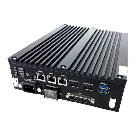
2. CE50-10 Names and Functions of Parts 2.1 Indicators and controls on the unit Figure 2‒1: CE50-10 front view USB ports do not support a locking mechanism. A USB cable might become disconnected if it is inadvertently knocked, for example. If necessary, fix the USB cable to the retainer clamp (for USB cables) on the front of the unit by using, for example, a cable tie. -
Page 29: Lan Connectors (Lan0, Lan1, Lan2)
2. CE50-10 Names and Functions of Parts Note Do not operate the test mode switch. If the shipping configuration (AUTO mode) is changed, the unit does not operate normally. 2.1.4 LAN connectors (LAN0, LAN1, LAN2) Connect LAN cables to these ports. 2.1.5 Main power switch (MAIN POWER) -
Page 30: Status Lamp (Status)
2. CE50-10 Names and Functions of Parts 2.1.8 STATUS lamp (STATUS) This lamp indicates the operating status of the unit. Table 2‒3: STATUS lamp (STATUS) Lamp Description Green Indicates that the OS is running. Indicates that the BIOS is running, the OS is starting, or the unit stopped due to an error. -
Page 31: Lan Link/Act Lamp (Lan0, Lan1, Or Lan2)
2. CE50-10 Names and Functions of Parts 2.1.12 LAN LINK/ACT lamp (LAN0, LAN1, or LAN2) This lamp indicates the link status and communication status of the LAN. Table 2‒7: LAN LINK/ACT lamp (LAN0, LAN1, or LAN2) Lamp Description Solid green Indicates that a link has been established. -
Page 32: Security Slot
2. CE50-10 Names and Functions of Parts 2.2 Security slot The security slot provided on the rear of the unit is used to secure the unit by using an anti-theft lock. Figure 2‒2: CE50-10 diagonal view Note The product does not include an anti-theft lock. -
Page 33: Operating The Power Supply Of The Ce50-10
Operating the Power Supply of the CE50-10 This chapter describes operating the power supply of the CE50-10 and provides important information. -
Page 34: Precautions
3. Operating the Power Supply of the CE50-10 3.1 Precautions 3.1.1 Before turning on the power Before turning off the power, see the precautions in the following: • 1.1 Prerequisites • 1.1.1 Rated power supply • 1.1.2 Installation of the unit... -
Page 35: Turning On The Power To The Ce50-10
3. Operating the Power Supply of the CE50-10 3.2 Turning on the power to the CE50-10 Turning on the power to the unit starts the OS. 3.2.1 Starting the unit To start the unit: 1. Make sure that the power cable and ground cable are correctly connected to the unit. -
Page 36: Turning Off The Power To The Ce50-10
To restart the unit after it is stopped, perform the steps in 3.3.2 Turning off the power to the CE50-10, and then perform the steps in 3.2 Turning on the power to the CE50-10. At this time, after turning off the power to the unit, wait at least 1 minute ( 3.3.2 Turning off the power to the CE50-10 ) before turning the power on again ( 3.2 ... -
Page 37: Stopping The Ce50-10 In The Case Of An Emergency
3. Operating the Power Supply of the CE50-10 3.4 Stopping the CE50-10 in the case of an emergency WARNING If you notice any sign of serious damage in the unit (for example, smoke or an unusual odor), immediately turn off the main power switch (MAIN POWER) and contact us. If you contracted maintenance services, contact the maintenance personnel. -
Page 39: External Contact Functions
External Contact Functions This chapter describes the external contact interfaces of the CE50-10. The external contact functions cannot run without an OS. -
Page 40: Psdown (Ext)
4. External Contact Functions 4.1 PSDOWN (EXT) 4.1.1 Signal name PSDOWN, DO0_GND 4.1.2 Description Power-off signals. These signals indicate that power to the target unit is turned off. 4.1.3 Specifications Table 4‒1: PSDOWN contact specifications Item Specifications Output specifications Output method Photo-MOS relay contact (Form B contact) Load voltage Max. -
Page 41: Do (Ext)
4. External Contact Functions 4.2 DO (EXT) 4.2.1 Signal name • DO_01, DO_02, DO_03, DO_04, DO_05, DO0_GND • DO_06, DO_07, DO_08, DO_09, DO_10, DO1_GND 4.2.2 Description General-purpose contact output signals. Meanings of the signals can be defined for each system by using a user program. 4.2.3 Specifications Table 4‒3: DO contact specifications Item... -
Page 42: Connection Diagram
4. External Contact Functions 4.2.5 Connection diagram Figure 4‒2: Connection diagram... -
Page 43: Di (Ext)
4. External Contact Functions 4.3 DI (EXT) 4.3.1 Signal name DI_01, DI_02, DI_03, DI_04, DI_GND 4.3.2 Description General-purpose contact input signals. Meanings of the signals can be defined for each system by using a user program. 4.3.3 Specifications Table 4‒5: DI contact specifications Item Specifications Input specifications Input method Photocoupler contact Rated input voltage... -
Page 45: Configuring Software Environment
Configuring Software Environment This chapter describes how to configure the OS settings of the CE50-10. This chapter also describes the procedures for the development and registration of application programs. -
Page 46: Constructing The Setup Environment
5. Configuring Software Environment 5.1 Constructing the setup environment When you set up a unit or install application programs, you need to connect a unit containing a development environment (development unit) to the target unit (unit to be set up). The development environment and the target unit can also be consolidated into a single unit. -
Page 47: Logging In To The Unit After Powering It On For The First Time
5. Configuring Software Environment 5.2 Logging in to the unit after powering it on for the first time When you start the unit for the first time, you need to log in using the default user information shown in the table below and then change the password. Table 5‒1: Default user information User name Password... -
Page 48: Using The Desktop
5. Configuring Software Environment 5.3 Using the desktop 5.3.1 Starting the desktop To start the desktop: 1. Start the unit in normal mode. You cannot use the desktop in maintenance mode. For details about how to change the OS operation mode, see 5.14 Changing OS operation mode. 2. - Page 49 5. Configuring Software Environment The desktop is now available. Important note In rare cases, desktop icons might overlap each other. In such cases, you can align the icons by right-clicking a desktop area where no icons exist, and then clicking Organize Desktop by Name.
-
Page 50: Stopping The Desktop
5. Configuring Software Environment 5.3.2 Stopping the desktop You must restart the unit to stop the desktop. To do this: 1. Click the power icon in the upper right corner of the desktop. In the menu that appears, click the power icon. 2. - Page 51 5. Configuring Software Environment 3. Enter the following command in the Terminal screen. $ gsettings set org.gnome.desktop.background show-desktop-icons false The icons are hidden in the desktop as shown below. 4. To re-display the icons on the desktop, run the following command on the Terminal screen.
- Page 52 5. Configuring Software Environment $ gsettings set org.gnome.desktop.background show-desktop-icons true...
-
Page 53: Setting Up The Display
5. Configuring Software Environment 5.4 Setting up the display This section describes how to set the resolution for the display connected to the unit and how to set up dual displays. To set up the display, you need to start the desktop. For details about how to start the desktop, see 5.3.1 Starting the desktop. -
Page 54: Setting Up Dual Displays
Note that any change made in the settings by clicking Keep Changes will be retained after the unit restarts. Figure 5‒4: Popup screen (2) Available resolutions The following lists the display resolutions supported by the CE50-10. Display colors can be set in 24 bits (16,777,216 colors). Table 5‒2: Display resolution information... - Page 55 5. Configuring Software Environment Figure 5‒5: Current display mode (Join Displays) Note In the product, the monitor model is displayed in place of Display1 and Display2. 4. Select Single Display, and then select the display on which the screen is to be displayed. Figure 5‒6: Selecting Single Display 5.
- Page 56 5. Configuring Software Environment Figure 5‒7: Apply button in the Displays screen 6. Click Keep Changes within 20 seconds. The mode is changed to single display. If you do not click Keep Changes within 20 seconds or if you click Revert Settings, the change is not applied and the original setting is retained. Note that any change made in the settings by clicking Keep Changes will be retained after the unit restarts.
-
Page 57: Specifying Ip Address And Ipv6 Network
5. Configuring Software Environment 5.5 Specifying IP address and IPv6 network 5.5.1 Configuring the network (1) Network settings when the unit is provided The following shows the default values of the IP address, network address, and communication mode for the LAN ports. Network interface definition file: /etc/netplan/50-cloud-init.yaml Table 5‒3: Default values for LAN ports Port (logical name) IP address... -
Page 58: Ip Multicast
5. Configuring Software Environment To change the IP address or network class, change the value of the bold underlined part. Add an IPv6 address. You can omit leading zeros in the string of numeric values separated by colons. To specify multiple IP addresses for one interface, add the IP address in the addresses key. Note that Netplan does not support interface aliases. -
Page 59: Using Ipv6
5. Configuring Software Environment 5.5.3 Using IPv6 IPv6 allows you to use the UDP and TCP communication functions. (1) Overview of definition information files The following shows the definition files that must be configured before you can use the IPv6 functions. For detailed contents, see the online manual in the development environment. - Page 60 5. Configuring Software Environment 2. (Optional) Specify the definition information for using the IPv6 address automatic allocation function. To automatically allocate IPv6 addresses, specify the following definition information (in addition to basic information) in the setting fields for the device to be specified. dhcp6: true -------- accept-ra: true...
-
Page 61: Configuring A Tagged Vlan
5. Configuring Software Environment 5.6 Configuring a tagged VLAN You can configure tagged VLANs for NIC (Network Interface Card) of this unit. A maximum of 4,094 tagged VLANs can be configured for one NIC. Specify tagged VLAN IDs in the range from 1 to 4094. 5.6.1 Configuring the network definition file To use the tagged VLAN function, add definition information to the network definition file. - Page 62 5. Configuring Software Environment (3) Starting the tagged VLAN The following example shows how to run the command to restart the stopped tagged VLAN. $ sudo ip link set ethX.128 up...
-
Page 63: Configuring Nic Bonding
Bonding of multiple NICs into a virtual NIC can increase availability of network communication and provide load distribution and redundancy. The CE50-10 supports bonding by using the standard function of Linux. This section describes how to configure bonding. For details, see the online manual. - Page 64 5. Configuring Software Environment Operation mode Description balance-alb Load distribution is also applied to packet reception in addition to the function of balance-tlb.
-
Page 65: Setting The Time Function
5.8.2 Setting the time zone for the OS time The OS time of the CE50-10 is set to UTC (Coordinated Universal Time) at the time of product shipment. If you want to display the OS time in your preferred local time zone, specify the following settings. - Page 66 5. Configuring Software Environment 2. Set the time zone. Run the following command to set the time zone. $ sudo timedatectl set-timezone TIMEZONE Any time zone in the list Important note Even if you change the time zone, the RTC time displayed in the BIOS menu remains in UTC. If you change the time by using timedatectl, the time converted to UTC is written to RTC.
-
Page 67: Changing The Operation To Be Performed In The Case Of A Disk Fault
If you want to change this setting so that operation of the unit continues after a disk fault or a slowdown detection, you need to change the definition file settings. Definition files • Definition file for disk faults: /hitachi/etc/dskptrl_stop.conf • Definition file for slowdown detection: /hitachi/etc/slowdown_stop.conf Item specified in a definition file stop definition-value --- (A) Specify 0 or 1. -
Page 68: Developing Application Programs
5.10 Developing application programs Application programming is performed by using this product. In addition to Linux standard development software, CE50-10 has an SDK to which various libraries for using unique functions are added. 5.10.1 Development environment hardware configurations (1) Hardware configuration No. 1 A personal computer (PC) is connected to the unit as a human-machine interface device. -
Page 69: Supported Functions
The ssh command is supported for remote operations. 5.10.3 Provided files Table 5‒10: Files for application development by using the unique functions of CE50-10 below shows the files provided for using the unique functions of CE50-10. Table 5‒10: Files for application development by using the unique functions of CE50-10... -
Page 70: Note About Ssd Life
5. Configuring Software Environment Application File name Description Development of /hitachi/usr/include/ecextioctl.h Include file for I/O extended I/O device board I/O devices operation programs Path definition for /etc/ld.so.conf.d/ctrl_edge_dev.conf Development additional libraries environment definition file 5.10.4 Note about SSD life The SSD installed in this unit is specified to operate for 10 years or more, based on a daily amount of write data of 50 GB or less. -
Page 71: Registering Application Programs
Figure 5‒11: Environment for constructing applications below shows the environment used to construct assumed applications. A single CE50-10 can be used as the development unit and as the construction unit . In this case, there is no need to transfer the master file of the application program. -
Page 72: Setting Up The User Area
5. Configuring Software Environment Figure 5‒12: Application installation procedure 5.11.3 Setting up the user area (1) Procedure for setting up the user area In the SSD user area, create a desired partition and then mount it for use. Figure 5‒13: Overview of the user area setting procedure below shows the procedure for specifying settings to automatically mount the user area when the OS starts. - Page 73 5. Configuring Software Environment (a) Dividing the user area Use the gdisk command to divide the user area (create partitions). For details about the procedure, see (2) Creating partitions, (3) Displaying partitions, and (4) Deleting partitions in 5.11.3 Setting up the user area. (b) Creating a file system Create a file system by using the mkfs command.
- Page 74 5. Configuring Software Environment GPT: not present Creating new GPT entries. Command (? for help): 2. Enter n to run the command that creates a new partition. Command (? for help):n 3. Enter the partition number you want to create. If you press the Enter key without entering anything, the smallest unused number is allocated. The following example indicates that the ninth partition is created.
- Page 75 5. Configuring Software Environment (3) Displaying partitions The following describes the procedure for displaying partitions. Two methods are available. The following describes the procedure for each method. (a) Display method 1 1. Start the gdisk command with /dev/sda specified for the argument. $ sudo gdisk /dev/sda GPT fdisk (gdisk) version 1.0.3 Partition table scan: MBR: protective...
- Page 76 To automatically mount the user area when starting the unit, you need to add a definition in the mount definition file (/hitachi/etc/fsconf). By specifying the file definition items, you can automatically reconfigure the file system (by using mkfs) if an attempt to repair the file system fails or automatically mount the file system if its status is normal.
-
Page 77: Setting Start And Stop Of Application Programs
5. Configuring Software Environment Definition item DescriptionSpecify the full path name of the mount destination directory. The specified directory is automatically created by the OS. Specify the file system type. The applicable file system is EXT4 only. Specify either of the following as the write mode to be used when the file system is mounted: •... -
Page 78
5. Configuring Software Environment [Service] ExecStart=
ExecStop= Type= RemainAfterExit= (edge-normal.target) Table 5‒12: Settings of the systemd script Item Description description Enter the description of the service. prerequisite-service Specify the service (required-service) to be started if it is not running when the application starts. - Page 79 5. Configuring Software Environment Run the following command to check whether automatic startup is enabled. $ sudo systemctl is-enabled application-name If automatic startup is enabled, enabled is displayed. If automatic startup is disabled, disabled is displayed.
-
Page 80: Setting The Security Functions
5. Configuring Software Environment 5.12 Setting the security functions You can use the following functions to safely operate the unit. Table 5‒13: Security functions Function name Description Login policy This function prevents unauthorized logins. Password policy This function defines the length, complexity, and update period of passwords. Firewall This function closes unused ports and blocks invalid packets. -
Page 81: Setting Password Policies
5. Configuring Software Environment $ sudo passwd -l root passwd: password expiry information changed. (2) Setting account lock for a failed login This function prohibits login for a certain period after a certain number of login attempts fail due to password error. This function is enabled by default. - Page 82 8 characters, must include at least 5 different types of characters, and must not be an easily guessable word such as password, qwerty, or hitachi. 1. To set this function, edit the configuration file.
- Page 83 5. Configuring Software Environment # password policy configuration password requisite pam_pwquality.so retry=3 minlen=8 ucredit=-1 lcredit=-1 dcredit=-1 ocredit=-1 reject_username enforce_for_root In this case, the following conditions are set: • The password must contain at least eight characters. • The password must contain at least one uppercase alphabetic letter, one lowercase alphabetic letter, one number, and one symbol.
-
Page 84: Setting Up A Firewall
5. Configuring Software Environment 5.12.3 Setting up a firewall Run the iptables or ip6tables command to set up a firewall. Use iptables to set up a firewall for IPv4 communication, and use ip6tables to set up a firewall for IPv6 communication. The following describes how to use the iptables command. When setting up a firewall for IPv6, replace iptables with ip6tables in the command execution examples. - Page 85 5. Configuring Software Environment Figure 5‒14: Procedure for setting the rules Note The rule settings are applied when the command is run. For example, if you perform an operation to cancel the reception permission of the SSH port while an SSH connection is being established, the ongoing communication may be disconnected and SSH login may be disabled. (a) Setting the port permitted for reception 1.
- Page 86 5. Configuring Software Environment (c) Setting the port permitted for reception with a limitation 1. Run the following command to permit reception on a port with a given port number while the number of connections that can be established per minute is limited. Note Before running the command, you must delete the existing reception permission, if any.
- Page 87 5. Configuring Software Environment $ sudo /etc/init.d/netfilter-persistent save...
-
Page 88: Setting Host Names
5. Configuring Software Environment 5.13 Setting host names You can set the host name for the unit by editing the /etc/hostname file. By default, ctrl-edgen is set. $ sudo vi /etc/hostname After editing the file, save it and then terminate processing. To exit the vi command, use :wq (write quit). Then, use the hostname command to apply the host name you have set. -
Page 89: Changing Os Operation Mode
5. Configuring Software Environment 5.14 Changing OS operation mode 5.14.1 What is the OS operation mode? You must change the OS operation mode depending on whether you perform normal operation or maintenance work. (1) Normal mode This mode allows you to start the OS and then operate user programs such as application programs. The factory default of the unit is normal mode. -
Page 90: Changing Maintenance Mode To Normal Mode
5. Configuring Software Environment Run the showecmode command to check the next OS operation mode. Confirm that the display for Next has changed to Maintenance mode (see the bold underlined part). $ sudo showecmode Current : Normal mode Next : Maintenance mode 5. - Page 91 5. Configuring Software Environment 5. Stop the unit. Run the shutdown command to stop the unit, and then turn off the power. $ shutdown -h 0 6. Unplug or connect the LAN cable. Disconnect the cable connecting to the maintenance PC if it has been connected during maintenance work. Connect the LAN cables to the remainder of the system, which has been temporary disconnected during maintenance work.
-
Page 92: Backup, Restoration, And Program Updates
5. Configuring Software Environment 5.15 Backup, restoration, and program updates The following functions are available for managing software installed in the unit: • Backup function • Restore function • Program update function Figure 5‒15: Flow of operations 5.15.1 Device configuration when using each function To back up or restore data or update programs, you need to connect the necessary peripherals to the unit. - Page 93 5. Configuring Software Environment Figure 5‒16: Configuration for connecting a USB flash drive and maintenance PC to the unit (2) Configuration No. 2 In this configuration, only the maintenance PC is connected to the unit. Table 5‒17: Device connected to the unit in configuration No. 2 Connection Device Description...
-
Page 94: Creating And Formatting Partitions In The External Media
5. Configuring Software Environment Figure 5‒18: Configuration for connecting the keyboard, display, and USB flash drive to the unit 5.15.2 Creating and formatting partitions in the external media In the external media to be used for the functions, create and format partitions in advance. The following describes how to create partitions in the external media and then create a file system. -
Page 95: Backing Up Storage Data
5. Configuring Software Environment 5.15.3 Backing up storage data (1) Overview of backup When you perform backup, data in the storage of the unit is saved in the external media or maintenance PC. The following data can be backed up. Table 5‒19: Data that can be backed up Data type File or device name Partition information... - Page 96 5. Configuring Software Environment Figure 5‒19: Flow of backup steps in configuration No. 1 1. Check the communication between the maintenance PC and the unit. Run the ping command to confirm that the maintenance PC can communicate with the unit. $ ping IP-address-of-the-target-unit 2.
- Page 97 5. Configuring Software Environment • The backup destination, the range of target partitions, and a message indicating the processing status are displayed. Then, a message asking you whether you want to verify the saved backup files appears. Enter y to verify the files, or enter N to skip the verification. •...
- Page 98 5. Configuring Software Environment (b) Operation procedure Use the remote operation terminal to remotely log in to the unit in which the information to be backed up is stored, and then run the backup command. Then, save the backup files in the maintenance PC by using the scp operation terminal.
- Page 99 5. Configuring Software Environment • When the backup menu appears, enter 2 (see the underlined part), and then press the Enter key to start backup. • The backup destination, the range of target partitions, and a message indicating the processing status are displayed.
- Page 100 5. Configuring Software Environment $ exit To change the OS operation mode to normal mode, see 5.14.4 Changing maintenance mode to normal mode. (4) Backing up data in configuration No. 3 The following describes the procedure for backing up data in the external media connected to the unit. (a) Preparation •...
-
Page 101: Restoring Backup Data
5. Configuring Software Environment 2. Confirm that the OS operation mode is set to maintenance mode. Run the showecmode command to confirm that the bold underlined parts are displayed as follows. $ sudo showecmode Current : Maintenance mode Next : Maintenance mode 3. - Page 102 5. Configuring Software Environment (2) Restoring data in configuration No. 1 The following describes the procedure for restoring backup data from the external media connected to the unit. (a) Preparation • Stop the unit, and then connect it with the maintenance PC by using an Ethernet cable. If necessary, disconnect other devices from the unit.
- Page 103 5. Configuring Software Environment Example user name: edgeadm login: edgeadm Password: ******* 3. Confirm that the OS operation mode is set to maintenance mode. Run the showecmode command to confirm that the bold underlined parts are displayed as follows. $ sudo showecmode Current : Maintenance mode Next...
- Page 104 5. Configuring Software Environment To change the OS operation mode to normal mode, see 5.14.4 Changing maintenance mode to normal mode. (3) Restoring data in configuration No. 2 The following describes the procedure for restoring backup data from the maintenance PC connected to the unit. (a) Preparation •...
- Page 105 5. Configuring Software Environment $ ping IP-address-of-the-target-unit 2. Remotely log in to the unit from the maintenance PC by using the remote operation terminal. Remotely log in to the unit as a user who can run the sudo command. Example user name: edgeadm login: edgeadm Password: ******* 3.
- Page 106 5. Configuring Software Environment (4) Restoring data in configuration No. 3 The following describes the procedure for restoring backup data from the external media connected to the unit. (a) Preparation • Change the OS operation mode of the unit from normal mode to maintenance mode. •...
-
Page 107: Updating The Os
Use this function when you need to update the OS because, for example, measures must be taken for security threats or new functions are required. Only OSs supplied by Hitachi for CE50-10 can be used. (1) Overview of the active area and inactive area Two partitions in the unit are assigned to system area 1 and system area 2 (device file names: /dev/sda2 and /dev/sda3). - Page 108 5. Configuring Software Environment (2) Note If an error is detected during the execution of the ecosupdate command, the active area is not changed. If an error is detected while the active area is being changed, the OSs in both areas might be placed in an inactive state. In this case, you need to eliminate the cause of the error by referring to the error message, and then rerun the command.
- Page 109 5. Configuring Software Environment Figure 5‒25: Flow of OS update steps in configuration No. 1 1. Check the communication between the maintenance PC and the unit. Run the ping command to confirm that the maintenance PC can communicate with the unit. $ ping IP-address-of-the-target-unit 2.
-
Page 110
5. Configuring Software Environment Run the rxversion command to check the device file names and OS versions for the active area and inactive area (see the bold underlined parts). $ sudo rxversion
(/dev/sda2) CTRL-EDGEN-IMG model-name version-information (/dev/sda3) CTRL-EDGEN-IMG model-name version-information version-information ... -
Page 111
5. Configuring Software Environment $ sudo rxversion
(/dev/sda2) CTRL-EDGEN-IMG model-name version-information (/dev/sda3) CTRL-EDGEN-IMG model-name version-information version-information version-information version-information 15. Log out from the unit. $ exit (4) Updating the OS in configuration No. 2 The following describes the procedure for updating the OS of the unit with the OS file in the maintenance PC connected to the unit. - Page 112 5. Configuring Software Environment Figure 5‒26: Flow of OS update steps in configuration No. 2 1. Check the communication between the maintenance PC and the unit. Run the ping command to confirm that the maintenance PC can communicate with the unit. $ ping IP-address-of-the-target-unit 2.
-
Page 113
5. Configuring Software Environment CTRL-EDGEN-IMG model-name version-information
(/dev/sda2) CTRL-EDGEN-IMG model-name version-information version-information version-information version-information 4. Send the update files from the maintenance PC to a path on the unit (for example, /mnt/osupdate). • Files to be sent OS file: osprog_base.zip OS version information file: OSverinfo •... - Page 114 5. Configuring Software Environment $ sudo showecmode Current : Normal mode Next : Normal mode Then, run the rxversion command to check the device file names and OS versions for the active area and inactive area (see the bold underlined parts). In this example, confirm that the device file name of the active area is /dev/sda2.
- Page 115 5. Configuring Software Environment Figure 5‒27: Flow of OS update steps in configuration No. 3 1. Log in to the unit. Log in to the unit as a user who can run the sudo command. Example user name: edgeadm login: edgeadm Password: ******* 2.
-
Page 116
5. Configuring Software Environment $ sudo rxversion
(/dev/sda2) CTRL-EDGEN-IMG model-name version-information (/dev/sda3) CTRL-EDGEN-IMG model-name version-information version-information version-information version-information 5. Run the OS update command. Run the ecosupdate command to update the OS in the inactive area and switch the system area that will be the active area the next time the unit starts to the area containing the updated OS. - Page 117 5. Configuring Software Environment version-information 13. Log out from the unit. $ exit...
-
Page 118: Watchdog Timer
5. Configuring Software Environment 5.16 Watchdog timer Watchdog timer (WDT) is a function that monitors the execution times of the OS and processes. If one of the execution times exceeds its predefined time limit (timeout), WDT interprets it as a fault and restarts the unit. A function that monitors whether the OS is properly working is called a hardware WDT. -
Page 119: Swdt.conf Definition File
If this file does not exist or a value outside the specifiable range is specified, monitoring with all default parameters is performed. If the same symbol is specified more than once, the last defined value takes effect. (1) File /hitachi/etc/swdt.conf (2) Setting items Table 5‒21: Setting items... -
Page 120: Checking The Cpu Usage Ratio
Ratio of the idle time during which the CPU is not used (= 100% - us - sy - wa -st) Ratio of the I/O wait time Ratio of the time for which usage is restricted by the virtual machine For the CE50-10, 0 is always displayed. -
Page 121: Command Reference
5. Configuring Software Environment 5.18 Command reference This section describes the commands supported for this unit. Table 5‒23: List of commands Command name Description Reference ecmodeset Set the next OS startup mode. 5.18.1 ecmodeset showecmode Display the OS startup mode. 5.18.2 showecmode ecbackup Back up data. 5.18.3 ecbackup ecrestore Restore backup data. -
Page 122: Showecmode
5. Configuring Software Environment $ sudo ecmodeset -enable Set next boot: Maintenance mode The following is displayed when normal mode is set as the next OS start mode. $ sudo ecmodeset -disable Set next boot: Normal modeFor the exit code, 0 is returned if the status is normal and 1 is returned if an error is detected. Table 5‒24: List of ecmodeset command error messages below shows error messages that are output when an error is detected. -
Page 123: Ecbackup
5. Configuring Software Environment 5.18.3 ecbackupecbackup - Back up data. ecbackup This command backs up data. When you run the command, the system waits for you to enter information. Perform backup according to the menu. No options need to be specified. Any specified options are ignored. ... - Page 124 5. Configuring Software Environment Item Display Description Backup targets: /dev/ The partitions or directories to be backed up sda8 /dev/sda9 /dev/ sda10 /media/etc Partition /dev/sda8 backup The partition in which backup starts start. 31MiB 0:00:01 [16.1MiB/s] The storage status of the backup file being created in the external [====>...
- Page 125 5. Configuring Software Environment Verifying:20210525101010_sda8_01.gz ...(f) The file and the partition doesn't match. Retry?(y / N)y ...(g) 31MiB 0:00:01 [16.1MiB/s] [====> ] 25% ETA 0:00:02) ...(e) Will you verify backup files(y / N)? y ...(f) Verifying: 20210525101010_sda8_01.gz ...(f) Finished:/mnt/ebackup_data/ecbackup_20210525101010/ 20210525101010_sda8_01.gz: xxx,xxx,xxx bytes ...(h) Please get 20210525101010_sda8_01.gz.
-
Page 126: Ecrestore
5. Configuring Software Environment Table 5‒27: List of ecbackup command error messages Error message Description Action Backup failed. Backup was suspended due to an error. Eliminate the cause of the error, and then rerun the command. ecbackup won't run An attempt was made to run the Change the mode to maintenance on Normal mode. - Page 127 5. Configuring Software Environment Restoration starts from the selected data, and then the screen is displayed as follows. Making partitions finished..(a) Restoring from extra media..(b) Restoring: 20210525101010_sda8_01.gz (start=0 size=123456) ...(c) 31MiB 0:00:01 [16.1MiB/s] [====> ] 25% ETA 0:00:02 ...(d) Will you verify restored area(y / N)?y ...(e) Verifying: 20210525101010_sda8_01.gz...
- Page 128 5. Configuring Software Environment Item Display Description Finished: 20210525101010_sda8_0 This message indicates that restoration of the relevant 1.gz backup files finished normally. Finished: 20210525101010_etc_01 .tgz Messages (c) through (g) are displayed for all the files in the specified directory. Successfully completed This message indicates that restoration of all backup files finished normally.
-
Page 129: Ecosupdate
Name of the directory where the OS update file (osprog_base.zip) and the OS version information file (OSverinfo) are stored-h option $ sudo ecosupdate Usage: /hitachi/bin/ecosupdate -h /hitachi/bin/ecosupdate Options: display this help message and exit directory name (ex. /tmp) -
Page 130: Rxosenable
Store the file again, and then rerun the command. ecosupdate: Failed to save / An attempt to save the boot partition file failed. hitachi/etc/ecosupdate/ Confirm that /hitachi/etc/ecosupdate/ is writable, and system<1|2>/boot.tgz then rerun the command. ecosupdate: Failed to save An attempt to save the root partition failed. -
Page 131
5. Configuring Software Environment
• -h, --help Displays the help message. • -p, --print Displays the OS version and partition number of the system area to be started next (default). • -s, --switch Changes the system area to be started next. This setting takes effect on and after the next startup. •... -
Page 132: Rxversion
5. Configuring Software Environment 5.18.7 rxversionrxversion - Display OS version information. rxversion [--nodate] This command displays the OS versions (master CD versions) of the active and inactive areas, BIOS version, RAS MCU firmware version, and TPM version. These versions are specific to the product and differ from the Linux versions. -
Page 133: Disklchk
Table 5‒34: List of rxversion command error messages Error message Description usage: /hitachi/bin/rxversion The specified argument is invalid. [ --nodate ] Note • Error If an attempt to collect any of the information items (1) to (11) shown in the display format fails, -- is output. -
Page 134: Fsconfchk
If no option is specified, the command checks the contents of the /hitachi/etc/fsconf file. • [confname] Specify the path of the file you want to check. If the file name is specified by the option, the command checks the contents of that file. -
Page 135: Showkxmessage
5. Configuring Software Environment 5.18.10 showkxmessageshowkxmessage - Display extracted KX messages. showkxmessage [ -i | -w | -e ] This command searches for KX messages recorded in log messages, and then displays the messages extracted according to the specified options. If no option is specified, the command displays all KX messages. The search results are displayed in order of the search results of /var/log/syslog so that KX messages are displayed in the order they were generated. -
Page 136: Eclogsave
• 2 Memory dump data in the memory dump area to tgz format (maximum of 100 MB) is collected. • 3 Log data registered in the user definition file (/hitachi/etc/save_applog.def) is compressed to tgz format and collected. • 4 System information that exists when the batch collection command is run is compressed to tgz format and collected. -
Page 137: Rasledctl
5. Configuring Software Environment Table 5‒38: List of eclogsave command error messages Error message Description Usage: eclogsave [ -d The specified argument is invalid. logtype ] eclogsave: Directory The specified directory does not exist. not found. eclogsave: Failed to The log files haven't be saved correctly due to a system error. create log files correctly. -
Page 138: Wdtctl
5. Configuring Software EnvironmentFor the exit code, 0 is returned if the status is normal and 1 is returned if an error is detected. 5.18.13 wdtctl wdtctl - Enable and disable hardware WDT. wdtctl Running this command with root privileges enables or disables hardware WDT (OS in-loop monitoring). Even after hardware WDT (OS in-loop monitoring) is disabled, restarting the unit enables hardware WDT (OS in-loop monitoring) again. -
Page 139: Force_Restart
However, because the definition of fixed priority process in-loop monitoring has a higher priority, if the command is issued when monitoring has stopped by /hitachi/etc/swdt.conf (OFF is defined for the INLOOP symbol), the command terminates abnormally without restarting monitoring. If the command is issued when monitoring has already started, the command terminates normally without doing anything. -
Page 140: Swdt_Stop
Note that this command temporarily stops the running software WDT. After the unit is restarted, the operation of the software WDT follows the definition of the INLOOP symbol in the /hitachi/etc/swdt.conf file.For the exit code, 0 is returned if the status is normal and 1 is returned if an error is detected. Table 5‒43: List of swdt_stop command error messages below shows error messages that are output when an error is detected. -
Page 141: Usbctl
5. Configuring Software Environment • If monitoring has stopped Soft-WDT is stopping.For the exit code, 0 is returned if the status is normal and 1 is returned if an error is detected. Table 5‒44: List of swdt_stat command error messages below shows error messages that are output when an error is detected. Table 5‒44: List of swdt_stat command error messages Error message Description... - Page 142 5. Configuring Software Environment Error message Description usbctl: device is not found. The GPIO driver has not started or the device file for accessing the driver cannot be opened. usbctl: I/O error. A hardware access error is detected. usbctl: usbctl library error. An error other than above is detected in the usbctl library.
-
Page 143: Managing User Accounts
Managing User Accounts This chapter describes how to add and delete user accounts for the CE50-10. -
Page 144: Adding A User Account
6. Managing User Accounts 6.1 Adding a user account This operation uses a sudo command. 1. Enter a user name, and then run the adduser command. Enter as follows. $ sudo adduser user-name --gecos "" 2. Enter a password. Enter a password that conforms to the policies. For details about the password policies, see 5.12.2 Setting password policies. -
Page 145: Deleting A User Account
6. Managing User Accounts 6.2 Deleting a user account This operation uses the sudo command. To delete a user account, specify the user name and then run the userdel command. $ sudo userdel -r user-name... -
Page 146: Changing The Password Of A User
6. Managing User Accounts 6.3 Changing the password of a user To change the password of a user who is logged in: 1. Log in to the OS as the user whose password is to be changed. 2. Run the passwd command. Enter as follows. -
Page 147: Managing Privileges For Sudo Command Execution
6. Managing User Accounts 6.4 Managing privileges for sudo command execution 6.4.1 Checking the existence of the privilege for sudo command execution 1. Run the id command with the user name specified. Enter as follows. $ id user-name 2. Check the execution result. If 27(sudo) appears after groups=, the user has the privilege for sudo command execution. -
Page 149: Maintaining The Ce50-10
Maintaining the CE50-10 This chapter describes maintenance of the CE50-10. -
Page 150: Bios Settings
7. Maintaining the CE50-10 7.1 BIOS settings BIOS containing system configuration information is stored in battery-backed-up SRAM (CMOS) and ROM. If you change the system configuration, BIOS settings might need to be changed. Note: At the time of product shipment, the BIOS settings are optimized for the system configuration. - Page 151 7. Maintaining the CE50-10 Exit: Used to save the changed configuration information to ROM, or to resume the defaults. (4) Setup menu details The following shows details of items that can be specified in each menu. Table 7‒2: BIOS setup menu list High order...
- Page 152 7. Maintaining the CE50-10 High order Set item Default Notes menu Security Secure Boot Configuration Do not change the settings. Supervisor Password is: Cleared User Password is: Cleared Set Supervisor Password Enter Supervisor Hint String Blank Set User Password Enter User Hint String Blank Min.
- Page 153 7. Maintaining the CE50-10 4. Open Boot in the high order menu. In Boot Priority Order, change the value to the default value. 5. Open Exit in the high order menu again. Position the cursor to Exit Saving Changes, and then press the Enter key.
-
Page 154: Daily User Maintenance Items
7. Maintaining the CE50-10 7.2 Daily user maintenance items Table 7‒4: Daily inspection itemss shows the items that we recommend the user to perform on a daily basis. Table 7‒4: Daily inspection items Item Frequency Description Cleaning Once a day Before starting operation, clean around the unit (the unit especially attracts dust due to static electricity). -
Page 155: Periodic Inspection Items
Similarly, make sure that the unit is not subject to vibration or physical impact when you move, carry, or transport it. • Table 7‒5: Periodic inspection items shows periodic inspection items. Hitachi is responsible for performing periodic inspection under maintenance contract. Only Hitachi staff and officially-trained personnel are permitted to perform periodic inspection. -
Page 156: Life-Limited Parts
Therefore, it takes time to find the cause of the problem. CAUTION This unit uses a lithium battery. When replacing the battery, you must use the one specified by Hitachi. Using any other battery might cause an explosion, fire, rupture, heat generation, leakage, or gas generation. -
Page 157: Troubleshooting
Troubleshooting This chapter describes troubleshooting of the CE50-10. -
Page 158: Troubleshooting Flow Chart
8. Troubleshooting 8.1 Troubleshooting flow chart Figure 8‒1: Front view of the unit The following shows the troubleshooting flow chart. -
Page 159: Smoke Or Unusual Odor
8. Troubleshooting Figure 8‒2: Troubleshooting flow chart 8.1.1 Smoke or unusual odor WARNING... -
Page 160: Power Lamp (Power) Does Not Light By Turning On The Power
8. Troubleshooting If there is smoke or an unusual odor, unplug the power cable plug from the outlet, and then contact us. Using the damaged unit might cause a fire or electric shock. 8.1.2 POWER lamp (POWER) does not light by turning on the power The unit might not be supplied with power. -
Page 161: Test Status Lamp (Test) Is Lit Green Or Red
1. Stop the unit (see 3.3.1 Stopping the unit). 2. Turn off the power supply connected to the unit (see 3.3.2 Turning off the power to the CE50-10). 3. Set the test mode switch (AUTO, TEST) to AUTO (see 2.1 Indicators and controls on the unit). -
Page 162: Cannot Turn Off The Power To The Unit
8. Troubleshooting 8.1.14 Cannot turn off the power to the unit Please contact us. -
Page 163: Collecting Maintenance Information
8. Troubleshooting 8.2 Collecting maintenance information The procedure for collecting maintenance information for the unit varies depending on the device configuration. This section describes how to collect maintenance information for each device configuration. For details about device configurations, see 5.15 Backup, restoration, and program updates. •... - Page 164 8. Troubleshooting Run the ping command to confirm that communication is possible between the maintenance PC and the unit. $ ping IP-address-of-the-target-unit 2. Log in to the unit from the maintenance PC via ssh. Log in to the unit via ssh as a user who can run the sudo command. Example user name: edgeadm $ ssh IP-address-of-the-target-unit...
- Page 165 8. Troubleshooting Figure 8‒4: Flow of maintenance information collection in configuration No. 2 The following describes the operation procedure and command input examples. When entering a command, check the underlined parts. 1. Check the communication between the maintenance PC and the unit. Run the ping command to confirm that communication is possible between the maintenance PC and the unit.
-
Page 166: Collecting Maintenance Information In Configuration No
8. Troubleshooting ### Started a compression of system information. ### ### Successfully completed.(20150801181021-eclog.tgz) ## 5. Use the ls command to check the size of the maintenance information file. $ ls /tmp -rw-r--r-- 1 0 873 Aug 1 18:10 20150801181021-eclog.list -rw-r--r-- 1 0 115753706 Aug 1 18:10 20150801181021-eclog.tgz 6. - Page 167 8. Troubleshooting Figure 8‒5: Flow of maintenance information collection in configuration No. 3 The following describes the operation procedure and command input examples. When entering a command, check the underlined parts. 1. Log in to the unit. Login: edgeadm Password: ******* 2. Confirm that the OS operation mode is set to maintenance mode. Run the showecmode command and confirm that the following is displayed (check the underlined parts).
- Page 168 8. Troubleshooting Start the target unit by turning on the power. For details about how to change the OS operation mode to normal mode, see 5.14.4 Changing maintenance mode to normal mode.
-
Page 169: Appendixes
Appendixes These appendixes describe the unit specifications, external interface, real-time clock specifications, connector specifications, error messages, option functions for application programs, library interface reference, security specifications, and communication sheet. -
Page 170: Unit Specifications
A. Unit Specifications A. Unit Specifications This appendix describes the CE50-10 unit specifications. A.1 Unit specifications Table A‒1: Unit specifications (1/2) Item Specification Model CE50-10 Ubuntu 18.04 LTS (Linux kernel 4.15) Processor (SoC) Intel Atom x7-E3950 Built-in drive unit mSATA SSD (64GB) x1, SATA 6.0 Gbps... -
Page 171: Operating Environmental Conditions
A. Unit Specifications Item Specification RAS function • Memory dump collection • PSDOWN contacts Weight 4kg or less Rated power 40W or less RTC time accuracy Plus-minus 9 seconds per day (when the ambient temperature is 25 degree Celsius) Plus-minus 6 seconds per day (when the ambient temperature is 25 degree System time accuracy Celsius) Lifetime... -
Page 172: Optional Parts
A. Unit Specifications Item Specification Humidity gradient Plus-minus 10%/h or less Dust General office level (0.3 mg/m : JEITA IT-1004B Class B) Complies with IP40. Corrosive gas Must not be present. (JEITA IT-1004B Class B (35 degree Celsius per 50%RH)) Vibration resistance 5.9 m/s (10 Hz, and 5s) Shock resistance... - Page 173 A. Unit Specifications Figure A‒1: Spec No. naming conventions Alphanumeric characters (Hard specification 1) 0: Without an external connection E: With an external connection Number (hard specification 2) 1: Memory 4 GB 2: Memory 8 GB Alphabetic character 1 (OS specification) S: Standard specification (Ubuntu) U: Without an OS (Hardware only) Alphabetic character 2 (software specification) A: With OpenVINO installed...
-
Page 174: External Interface
B. External Interface B. External Interface External interface information are described as follows: • Cable length specification for an external interface • Current specification for the USB 3.0 port and Display port B.1 Cable length specification for external interface Table B‒1: External interface cable length specification Interface name Cable length Remarks... -
Page 175: Real-Time Clock Specifications
C. Real-time Clock Specifications C. Real-time Clock Specifications This unit employs an RTC (real-time clock) IC for its internal clock. The RTC incorporates the calendar and continues to run on a backup battery while the power is off. Table C‒1: Real-time clock specifications Item Specification Clock function... -
Page 176: Connector Specifications
D. Connector Specifications D. Connector Specifications Connector specifications are described as follows: • USB 3.0 connector (USB3.0-1, USB3.0-2 ports) • LAN (RJ-45 8-pin) connector • DisplayPort connector (20-pin, male connector) • External contact (EXT) connector (D-sub25-pin, inch screw thread, male connector) D.1 USB 3.0 connector (USB3.0-1, USB3.0-2 ports) Figure D‒1: USB 3.0 pin assignment Table D‒1: USB 3.0 signal names Pin number... -
Page 177: Displayport Connector (20-Pin, Male Connector)
D. Connector Specifications Pin number Signal name Pin number Signal name TRD2+ TRD3- D.3 DisplayPort connector (20-pin, male connector) Figure D‒3: DisplayPort pin assignment Table D‒3: DisplayPort signal names Pin number Signal name Pin number Signal name Lane0+ Lane3- Lane0- Config1 Lane1+ Config2 AUX+ Lane1- Lane2+ AUX-... - Page 178 D. Connector Specifications Pin number Signal name Pin number Signal name DO_01 DO_02 DO_03 DO_04 DO0_GND DO1_GND DO_05 DO_06 DO_07 DO_08 DO1_GND DO1_GND DO_09 DO_10 DI_GND DI_GND DI_01 DI_03 DI_02 DI_04 DI_GND Note #1 DO0_GND is the return signal for PSDOWN and for DO_01 through DO_05. Note #2 DO1_GND is the return signal for DO_06 through DO_10.
-
Page 179: Error Messages
E. Error Messages E. Error Messages This appendix describes error messages of the CE50-10. • Error messages at unit startup • LAN error messages • SoC (System-on-a-chip) temperature error messages • Resource shortage error messages • I/O board error messages E.1 Error messages at unit startup Table E‒1: Error messages at unit startup... - Page 180 E. Error Messages Message ID Message Cause (meaning) Action KXDL001-W Link disconnected 2. Check the LAN cable for a fault Ethernet adapter(ethX) Link is (such as disconnection or loose down. connection). ethX: Interface name 3. Confirm that the type of the LAN cable (straight or cross) is correct.
-
Page 181: Soc (System-On-A-Chip) Temperature Error Messages
E. Error Messages Message ID Message Cause (meaning) Action KXDL200-I Link established None Ethernet adapter (ethX) Link is up at XXX Mbps, YYY duplex. ethX: Interface name XXX: 10, 100, or 1000 (Mbps) YYY: half or full (transmission method) E.3 SoC (System-on-a-chip) temperature error messages Table E‒3: SoC temperature error messages Message ID Message... -
Page 182: I/O Board Error Messages
E. Error Messages E.5 I/O board error messages Table E‒5: I/O board error messages Message ID Message Cause (meaning) Action DI read timeout KXDI001-W Processing contention might have DI software timeout occurred due to concurrent issuance of KXDO001-W DO write timeout I/O library functions. Revise the user DO software timeout program. -
Page 183: Option Functions For Application Programs
By using Docker, you can deploy application programs, libraries, and prerequisite programs as containers in the operation environment (CE50-10). A container is provided as a single image file. By transferring an image file from the development environment to the operation environment, you can run the application program in the same environment as the development environment. - Page 184 F. Option Functions for Application Programs $ sudo systemctl start docker (b) Stopping Docker Run the following command to stop Docker. $ sudo systemctl stop docker (c) Starting Docker when the OS starts Run the following command to start Docker when the OS starts. $ sudo systemctl enable docker (3) Loading image files on Docker The following describes how to transfer an image file to Docker and load it as a Docker image.
-
Page 185: Opc-Ua Client Function
F. Option Functions for Application Programs F.2 OPC-UA client function We provide the following programs to use the CE50-10 as an OPC-UA client. • Library: OSS Open62541 • Sample programs for operation verification: tutorial_server_variable.c (server program) and client.c (client program) (1) Compiling a program that uses the OPC-UA library To compile a C program that uses Open62541, run the following command. -
Page 186: Library Interface Reference
• xxx: Specify the object file name. • xxx.c: Specify the source file name. For details about include files and libraries that are to be specified when compiling the program, see Table 5‒10: Files for application development by using the unique functions of CE50-10. (2) Reference (a) Format #include... -
Page 187: Didoctl (Dido Input/Output Operation)
ETIMEDOUT is returned. (c) Arguments board Specify the access target I/O board number. For the CE50-10, specify BOARD_NO1, which is defined in ecextioctl.h. If a value other than BOARD_NO1 is specified, processing terminates abnormally, the return value is -1, and EINVAL is returned for the error number (errno). - Page 188 • If the external power supply of DO is lost due to a power failure or any other failure, DO data is not output but didoctl terminates normally. CE50-10 is unable to detect incorrect DO data output caused by a failure in an external power supply.
-
Page 189: Force_Restart (Forced Cpu Restart)
• xxx: Specify the object file name. • xxx.c: Specify the source file name. For details about include files and libraries that are to be specified when compiling the program, see Table 5‒10: Files for application development by using the unique functions of CE50-10. (2) Reference (a) Format #include... -
Page 190
• xxx: Specify the object file name. • xxx.c: Specify the source file name. For details about include files and libraries that are to be specified when compiling the program, see Table 5‒10: Files for application development by using the unique functions of CE50-10. (2) Reference (a) Format #include
... - Page 191 G. Library Interface Reference Figure G‒2: Return value when USB_STAT is specified ■ For abnormal termination For abnormal termination, -1 is returned and one of the following codes is returned for the error number (errno). EINVAL The argument has an error. ENXIO The driver for monitoring the hardware watchdog timer has not started, or the device file for accessing the driver cannot be opened.
-
Page 192: Security Specifications
Log files, which are stored in /var/log, are important for finding signs of security attacks or for investigating security accidents. There is a limit on the amount of log data that can be stored in CE50-10. Due to these specifications, log files are automatically deleted after a certain period has passed after the log data is generated. - Page 193 H. Security Specifications To update the algorithm used to perform encryption in the CE50-10: 1. Hitachi provides the new algorithm as package files (extension .deb) containing OpenSSL binary data that implements encryption. 2. Start the unit in normal mode. 3. Copy the package files.
- Page 194 I. Communication Sheet I. Communication Sheet If you need technical assistance from Hitachi during the troubleshooting of this product as described in 8. Troubleshooting, it is recommended that you first fill in the form shown in Table I‒1: Data sheet. Then share the data sheet with Hitachi's technical assistance personnel so as to expedite the process.