
Related Manuals for Marco UP8-RE


Summary of Contents for Marco UP8-RE
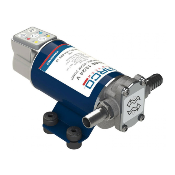
- Page 1 ELETTROPOMPA AUTOADESCANTE PER TRAVASO LIQUIDI SELF-PRIMING ELECTRIC PUMP FOR TRANSFERRING VARIOUS LIQUIDS AVVERTENZE D’USO INSTRUCTIONS FOR USE 164 095 15 - UP8-RE 12/24V © S.p.A.
- Page 2 FUNZIONI · Il circuito si accende: Pulsano il led verde e quello rosso, mentre effettua il self-check iniziale e gli azzeramenti dei parametri. Se qualcosa fallisce, la pompa non esce da questa condizione e il led rosso e verde continua a lampeggiare in modo indefinito. ·...
- Page 3 · Se il tasto “ON/OFF” viene tenuto premuto all'accensione fino a quando lampeggia il led verde, si inverte lo stato di partenza automatica (ovvero se la pompa parte da sola all'accensione o attende un input dall'utente prima di partire). · Se il tasto “TARTARUGA”...
-
Page 4: Segnalazione Errori
SEGNALAZIONE ERRORI · Se il circuito di controllo è costretto ad abbassare la velocità del motore per via del limitatore di potenza, arrivato a una soglia considerata come “funzionamento anormale” il led rosso comincerà a lampeggiare velocemente e dopo 5 secondi la pompa verrà fermata. ·... -
Page 5: Descrizione Del Dispositivo
DESCRIZIONE DEL DISPOSITIVO Elettropompa autoadescante per travaso liquidi di varia natura. Gli elementi pompanti sono costituiti da ingranaggi in bronzo che possono eventualmente girare a secco per brevi periodi. DATI TECNICI Tab.1 IT FUSIB ILE PRESSIONE PESO CAVI (**) CODICE TIPO VOLT PORTATA (*) -
Page 6: Condizioni Ambientali
CONDIZIONI AMBIENTALI ATTENZIONE: le temperature limite indicate si applicano ai componenti del dispositivo e devono essere rispettate per evitare possibili danneggiamenti o malfunzionamenti. CICLO DI LAVORO In condizioni di massima pressione la pompa subisce sollecitazioni superiori, pertanto si consiglia di non utilizzarla per tempi prolungati in queste condizioni. MOVIMENTAZIONE E TRASPORTO Peso e dimensioni del dispositivo non richiedono l'uso di mezzi di sollevamento particolari. - Page 7 Per la corretta direzione del flusso del liquido come indicato dalla freccia sulla parte superiore, è necessario collegare il polo positivo (+) della batteria al filo rosso che esce dalla calotta della pompa e il polo negativo (-), al filo nero. I collegamenti elettrici vanno eseguiti utilizzando morsettiere e connessioni adeguate con accurato serraggio dei conduttori.
-
Page 8: Problemi E Soluzioni
PROBLEMI E SOLUZIONI COSA VERIFICARE SE LA POMPA NON PARTE O SI ARRESTA? Ø Verificare l'efficienza del generatore (presenza di tensione) Ø Verificare se il fusibile è interrotto. Ø Verificare la presenza di corpi estranei nel corpo della pompa. Per effettuare ciò è necessario svitare le quattro viti di fissaggio, togliere il piattello di chiusura ed ispezionarne l'interno. -
Page 9: Garanzia
Marco S.p.A. Questi costi saranno limitati ai costi di spedizione tra il magazzino di Marco S.p.A. e la sede del cliente. 7) Nessuna nota di credito o reso sarà emessa prima di un test eseguito dal controllo di qualità... - Page 10 FEATURES · The circuit lights up: The green and red LEDs slowly flash, while the circuit is performing the initial self-check and parameter reset. If something fails, the pump does not come out of this condition and the red and green LEDs continue to blink indefinitely. ·...
- Page 11 · If the “ON/OFF” button is held pushed at power-on until the green led flashes, the automatic start of the pump is toggled (i.e. if the pump starts immediately after power on or if it waits an user input before starting). ·...
-
Page 12: Reporting Errors
REPORTING ERRORS · If the control circuit is forced to lower the motor speed due to the power limiter, when it reaches a threshold considered as "abnormal operation", the red LED will start to blinking quickly and after 5 seconds the pump will stop. ·... -
Page 13: Product Description
PRODUCT DESCRIPTION Self-priming electric pump for the transfer of liquids of varied nature. The pumping elements are made up of bronze gears which can possibly even run dry for brief periods. TECHNICAL DETAILS Tab.1 EN FUSE FLOW RATE (*) PRESSURE W EIG HT W IRE SIZE (**) CODE... -
Page 14: Ambient Conditions
AMBIENT CONDITIONS TEMPERATURE: min.-10°C 14°F-max.60°C 140°F RELATIVE HUMIDITY: max. 90 % WARNING: the above indicated temperature ranges are applicable to all components of the pump and these limits must be respected in order to avoid any possible damage or malfunctioning. OPERATING CYCLE Under conditions of high operating pressures the pump can be subjected to elevated stresses and overheating and therefore should not be used for prolonged periods under such... - Page 15 To ensure the correct directional flow of the fluid as indicated by the arrow on the top plate, it is necessary to connect the positive pole (+) of the battery supply to the red wire on the motor end-cap and the negative pole (-) to the black wire. Electrical connections must be made using adequate terminal blocks and connectors ensuring a tight fitment of the electrical cables.
-
Page 16: Troubleshooting
TROUBLESHOOTING CHECK POINTS IF THE PUMP HAS STOPPED OR WILL NOT START Ø Check the effectiveness of the battery power supply (voltage activity); Ø Check if the fuse has blown; Ø Check for any foreign matter present in the pump body. To do this, disconnect the power supply and unscrew the four fixing screws, remove the front cover plate and inspect the chamber. -
Page 17: Environmental Disposal
5) The Warranty does not cover any related installation costs involved. 6) Transport costs are refundable only in the case where warranty has been duly accepted by Marco Spa and they will be limited to the actual shipment costs between Marco Spa warehouse and the client's delivery address. - Page 18 SCHEDA DI ASSEMBLAGGIO / EXPLODED VIEW © S.p.A.
- Page 19 INGOMBRI / DIMENSIONS © S.p.A.
- Page 20 DIAGRAMMI / DIAGRAMS DIAGRAMMA PORTATA FLOW RATE DIAGRAM DIAGRAMMA ASSORBIMENTI AMPERE-DRAW DIAGRAM © S.p.A.
- Page 21 AVVERTENZA / WARNING SUPERFICIE CALDA / HOT SURFACE © S.p.A.
- Page 22 E.C. DECLARATION OF CONFORMITY Confermiamo che il prodotto: We confirm that the product: 164095 15 - UP8-RE 12/24V Pompa elettronica / Electronic Gear pump è conforme alla Direttiva 2014/30/UE (ex. 2004/108/CE) relativa alla compatibilità elettromagnetica e alla Direttiva 2006/42/CE relativa alle macchine.
- Page 24 Questo documento e' proprieta' di Marco S.p.A la riproduzione e l'uso sono vietati. Tutti i diritti sono riservati. Per ulteriori informazioni vedere nostro sito internet - www.marco.it Marco S.p.A Via Mameli 10 - 25014 Castenedolo (Brescia) – Italia tel. +39 030 2134.1 / Fax +39 030 2134.300 Property of MARCO S.p.A reproduction prohibited.