Table of Contents
Quick Links
Table of Contents

Related Manuals for Cisco Firepower 7010, Firepower 7020, Firepower 7030, Firepower 7050, Firepower 7110, Firepower 7120, Firepower 7115, Firepower 7125,


Summary of Contents for Cisco Firepower 7010, Firepower 7020, Firepower 7030, Firepower 7050, Firepower 7110, Firepower 7120, Firepower 7115, Firepower 7125,
- Page 1 Firepower 7000 Series Hardware Installation Guide First Published: July 22, 2016 Last Updated: July 12, 2018 Cisco Systems, Inc. www.cisco.com Cisco has more than 200 offices worldwide. Addresses, phone numbers, and fax numbers are listed on the Cisco website at www.cisco.com/go/offices.
- Page 2 OR ITS SUPPLIERS HAVE BEEN ADVISED OF THE POSSIBILITY OF SUCH DAMAGES. Cisco and the Cisco logo are trademarks or registered trademarks of Cisco and/or its affiliates in the U.S. and other countries. To view a list of Cisco trademarks, go to this URL: www.cisco.com/go/trademarks.
-
Page 3: Table Of Contents
C O N T E N T S About This Guide Organization Document Conventions Installation Warnings Where to Find Safety and Warning Information Related Documentation Obtaining Documentation and Submitting a Service Request About the Firepower 7000 Series Firepower 7000 Series Managed Devices Delivered with the Firepower System 7000 Series Device Chassis Designations Hardware Specifications Rack and Cabinet Mounting Options... - Page 4 Contents Allowing Network Reconfiguration Using the LCD Panel System Status Mode Information Mode Error Alert Mode Deploying on a Management Network Management Deployment Considerations Understanding Management Interfaces Single Management Interface Multiple Management Interfaces Deployment Options Deploying with Traffic Channels Deploying with Network Routes Security Considerations Special Case: Connecting 8000 Series Devices Deploying Firepower Managed Devices...
- Page 5 Contents Integrating with VPNs 6-18 Detecting Intrusions on Other Points of Entry 6-19 Deploying in Multi-Site Environments 6-20 Integrating Multiple Management Interfaces within a Complex Network 6-22 Integrating Managed Devices within Complex Networks 6-23 Power Requirements for Firepower 7000 Series Devices Warnings and Cautions Static Control Firepower 70xx Family Appliances...
- Page 6 Contents Firepower 7000 Series Hardware Installation Guide...
- Page 7 Released: July 22, 2016 This guide describes how to install and maintain the Cisco Firepower 7000 Series appliances. Information in this guide applies to the Cisco 70xx Family and the 71xx Family models. This preface includes the following sections: Organization, page v...
-
Page 8: About This Guide
About This Guide Document Conventions Chapter Title Description Chapter 6 Deploying Firepower Managed Describes how different sensing interfaces Devices affect the capabilities of the Firepower System, including passive, inline, routed, switched, and hybrid interfaces. Appendix A Power Requirements for Firepower Describes power requirements for Firepower 7000 Series Devices 7000 Series devices. -
Page 9: Installation Warnings
Means reader be careful. In this situation, you might perform an action that could result in equipment Caution damage or loss of data. Installation Warnings Be sure to read the Regulatory Compliance and Safety Information document (http://www.cisco.com/c/en/us/td/docs/security/firesight/hw-docs/regulatory/compliance/firesight-firep ower-rcsi.html) before installing the device. This section presents these important safety warnings: Power Supply Disconnection Warning, page vii •... - Page 10 About This Guide Installation Warnings Wrist Strap Warning Warning During this procedure, wear grounding wrist straps to avoid ESD damage to the card. Do not directly touch the backplane with your hand or any metal tool, or you could receive a shock. Statement 94 Work During Lightning Warning Warning Do not work on the system, or connect or disconnect cables during periods of lightning.
-
Page 11: Where To Find Safety And Warning Information
For safety and warning information, see the Regulatory Compliance and Safety Information document at the following URL: http://www.cisco.com/c/en/us/td/docs/security/firesight/hw-docs/regulatory/compliance/firesight-firep ower-rcsi.html This RCSI document describes the international agency compliance and safety information for the Cisco Firepower series. Firepower 7000 Series Hardware Installation Guide... -
Page 12: Related Documentation
About This Guide Related Documentation Related Documentation For a complete list of the Cisco Firepower series documentation and where to find it, see the documentation roadmap at the following URL: http://www.cisco.com/c/en/us/td/docs/security/firepower/roadmap/firepower-roadmap.html Obtaining Documentation and Submitting a Service Request For information on obtaining documentation, using the Cisco Bug Search Tool (BST), submitting a service request, and gathering additional information, see What’s New in Cisco Product Documentation... -
Page 13: About The Firepower 7000 Series
Only trained and qualified personnel should install, replace, or service this equipment. Statement 49 Warning Firepower 7000 Series Managed Devices Delivered with the Firepower System The following table lists the managed devices that Cisco delivers with the Firepower System. Table 1-1 7000 Series Firepower System Appliances... - Page 14 Chapter 1 About the Firepower 7000 Series Table 1-2 7000 Series Chassis Models Firepower and AMP Device Model Hardware Chassis Code 7010, 7020, 7030 CHRY-1U-AC 7050 NEME-1U-AC 7110, 7120 (Copper) GERY-1U-8-C-AC 7110, 7120 (Fiber) GERY-1U-8-FM-AC 7115, 7125, AMP7150 GERY-1U-4C8S-AC Firepower 7000 Series Installation Guide...
-
Page 15: Hardware Specifications
C H A P T E R Hardware Specifications Firepower 7000 Series devices are delivered on a variety of platforms to meet the needs of your organization. Rack and Cabinet Mounting Options You can mount Firepower devices in racks and server cabinets. The appliance comes with a rack-mounting kit except for the Firepower 7010, 7020, 7030, and 7050. - Page 16 Chapter 2 Hardware Specifications Firepower 7000 Series Devices Firepower 70xx Family Front View The front of the chassis contains the LCD panel, sensing interfaces, front panel, and management interface. Figure 2-1 Firepower 70xx Family (Chassis: CHRY-1U-AC; NEME-1U-AC) Front View The following table describes the features on the front of the appliance. Table 2-1 Firepower 70xx Family System Components: Front View Feature...
- Page 17 Chapter 2 Hardware Specifications Firepower 7000 Series Devices The front panel of the chassis houses LEDs, which display the system’s operating state. The following table describes the LEDs on the front panel. Table 2-3 Firepower 70xx Family Front Panel LEDs Description Reset button Allows you to reboot the appliance without disconnecting it from the power supply.
- Page 18 Chapter 2 Hardware Specifications Firepower 7000 Series Devices Sensing Interfaces The Firepower 70xx Family appliances are delivered with eight copper interfaces, each with configurable bypass capability. Figure 2-3 Eight-Port 1000BASE-T Copper Interfaces Use the following table to understand the activity and link LEDs on the copper interfaces. Table 2-5 Firepower 70xx Family Copper Link/Activity LEDs Status...
- Page 19 Chapter 2 Hardware Specifications Firepower 7000 Series Devices Table 2-7 Firepower 70xx Family Management Interface LEDs (continued) Description Right (activity) 7010/20/30 Indicates activity on the port. If the light is blinking, there is activity. If the light is off, there is no activity. 7050 For 10Mbps links, if the light is on, there is link and activity.
- Page 20 Chapter 2 Hardware Specifications Firepower 7000 Series Devices Table 2-9 Firepower 70xx Family Physical and Environmental Parameters Parameter Description Form factor 1U, half rack width Dimensions (D x W x H) Single chassis: 12.49 in. x 7.89 in. x 1.66 in. (31.74 cm x 20.04 cm x 4.21 cm) 2-Chassis Tray: 25.05 in.
-
Page 21: Firepower 7110 And 7120
Chapter 2 Hardware Specifications Firepower 7000 Series Devices Firepower 7110 and 7120 The Firepower 7110 and 7120 devices, part of the 71xx Family, are 1U appliances, and are delivered with eight copper or eight fiber interfaces, each with configurable bypass capability. See the Regulatory Compliance and Safety Information for FirePOWER and FireSIGHT Appliances document for safety considerations for 71xx Family appliances. - Page 22 Chapter 2 Hardware Specifications Firepower 7000 Series Devices Figure 2-7 Firepower 7110 and 7120 Front Panel Table 2-11 Firepower 7110 and 7120 Front Panel Components USB 2.0 connector NIC1 activity LED Reset button Solid-state drive activity LED NIC2 activity LED ID button System status LED Power button and LED...
- Page 23 Chapter 2 Hardware Specifications Firepower 7000 Series Devices The following table describes the conditions under which the system status LEDs might be lit. Table 2-13 Firepower 7110 and 7120 System Status Condition Description Critical Any critical or non-recoverable threshold crossing associated with the following events: •...
- Page 24 Chapter 2 Hardware Specifications Firepower 7000 Series Devices Table 2-14 Firepower 7110 and 7120 Copper Link/Activity LEDs Status Description Both LEDs off The interface does not have link. Link amber The speed of the traffic on the interface is 10Mb or 100Mb. Link green The speed of the traffic on the interface is 1Gb.
- Page 25 Chapter 2 Hardware Specifications Firepower 7000 Series Devices Table 2-17 Firepower 7110 and 7120 Fiber Bypass LEDs (continued) Status Description Steady amber The interface pair has been placed in bypass mode and is not inspecting traffic. Blinking amber The interface pair is in bypass mode; that is, it has failed open. Firepower 7110 and 7120 Chassis Rear View The rear of the chassis contains the management interface, connection ports, grounding studs, and power supplies.
- Page 26 Chapter 2 Hardware Specifications Firepower 7000 Series Devices Table 2-19 Firepower 7110 and 7120 Management Interface LEDs Description Left (activity) Indicates activity on the port: • A blinking light indicates activity. • No light indicates there is no activity. Right (link) Indicates whether the link is up: A light indicates the link is up.
-
Page 27: Firepower 7115, 7125, And Amp7150
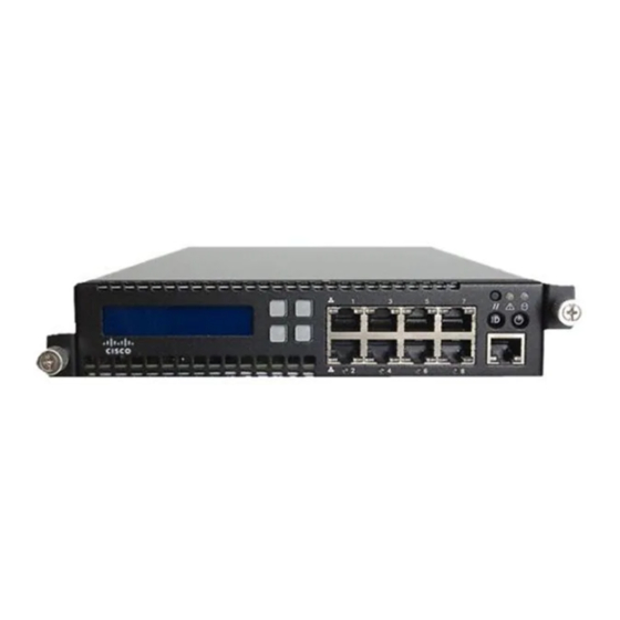
The Firepower 7115, 7125, and AMP7150 devices, part of the 71xx Family, are delivered with four-port copper interfaces with configurable bypass capability, and eight hot-swappable small form-factor pluggable (SFP) ports without bypass capability. To ensure compatibility, use only Cisco SFP transceivers. - Page 28 Chapter 2 Hardware Specifications Firepower 7000 Series Devices Firepower 7115, 7125, and AMP7150 Chassis Front View The front of the chassis contains the LCD panel, USB port, front panel, copper sensing interfaces, and SFP sockets. Figure 2-11 Firepower 7115, 7125, and AMP7150 (Chassis: GERY-1U-8-4C8S-AC) Front View The following table describes the features on the front of the appliance.
- Page 29 Chapter 2 Hardware Specifications Firepower 7000 Series Devices Table 2-24 Firepower 7115, 7125, and AMP7150 Front Panel LEDs Description NIC activity (1 and 2) Indicates whether there is any network activity: • A green light indicates there is network activity. •...
- Page 30 Chapter 2 Hardware Specifications Firepower 7000 Series Devices Table 2-25 Firepower 7115, 7125, and AMP7150 System Status Condition Description Critical Any critical or non-recoverable threshold crossing associated with the following events: • temperature, voltage, or fan critical threshold crossing • power subsystem failure system inability to power up due to incorrectly installed processors or processor •...
- Page 31 The interface pair is in bypass mode; that is, it has failed open. SFP Interfaces You can install up to eight hot-swappable Cisco SFP transceivers, available in 1G copper, 1G short range fiber, or 1G long range fiber. SFP transceivers do not have bypass capability and should not be used in intrusion prevention deployments.
- Page 32 Chapter 2 Hardware Specifications Firepower 7000 Series Devices Table 2-28 Firepower 7115, 7125, and AMP7150 SFP Socket Activity/Link LEDs Status Description Top (activity) For an inline interface: the light is on when the interface has activity. If dark, there is no activity. For a passive interface: the light is non-functional.
- Page 33 Chapter 2 Hardware Specifications Firepower 7000 Series Devices Table 2-30 Firepower 7115, 7125 and AMP7150 System Components: Rear View Features Description VGA port Allows you to attach a monitor, keyboard, and mouse to the device to establish a direct USB port workstation-to-appliance connection.
- Page 34 Chapter 2 Hardware Specifications Firepower 7000 Series Devices Table 2-32 Firepower 7115, 7125, and AMP7150 Power Supply LED (continued) Description Blinking green AC input is present; volts on standby, the power supply is switched off. Green The power supply is plugged in and on. Firepower 7115, 7125, and AMP7150 Physical and Environmental Parameters The following table describes the physical attributes and the environmental parameters for the appliance.
- Page 35 Chapter 2 Hardware Specifications Firepower 7000 Series Devices Table 2-33 Firepower 7115, 7125, and AMP7150 Physical and Environmental Parameters (continued) Parameter Description Cooling requirements 900 BTU/hour You must provide sufficient cooling to maintain the appliance within its required operating temperature range. Failure to do this may cause a malfunction or damage to the appliance. Acoustic noise 64 dBA at full processor load, normal fan operation Meets GR-63-CORE 4.6 Acoustic Noise...
- Page 36 Chapter 2 Hardware Specifications Firepower 7000 Series Devices Firepower 7000 Series Hardware Installation Guide 2 -22...
- Page 37 C H A P T E R Installing a Firepower 7000 Series Managed Device Firepower System appliances are easily installed on your network as part of a larger Firepower System deployment. You install devices on network segments to inspect traffic and generate intrusion events based on the intrusion policy applied to it.
- Page 38 • Effect of damage on the installation • Security Considerations Before you install your appliance, Cisco recommends that you consider the following: Locate your appliance in a lockable rack within a secure location that prevents access by • unauthorized personnel.
- Page 39 Chapter 3 Installing a Firepower 7000 Series Managed Device Identifying the Sensing Interfaces Identifying the Sensing Interfaces Firepower devices connect to network segments using sensing interfaces. The number of segments each device can monitor depends on the number of sensing interfaces on the device and the type of connection (passive, inline, routed, or switched) that you want to use on the network segment.
- Page 40 Chapter 3 Installing a Firepower 7000 Series Managed Device Identifying the Sensing Interfaces If you want to take advantage of the device’s automatic bypass capability, you must connect two interfaces vertically (interfaces 1 and 2, 3 and 4, 5 and 6, or 7 and 8) to a network segment. Automatic bypass capability allows traffic to flow even if the device fails or loses power.
- Page 41 Chapter 3 Installing a Firepower 7000 Series Managed Device Identifying the Sensing Interfaces Figure 3-4 Firepower 7110 and 7120 Fiber Interfaces Figure 3-5 Eight-Port 1000BASE-SX Fiber Configurable Bypass The eight-port 1000BASE-SX fiber configurable bypass configuration uses LC-type (Local Connector) optical transceivers. You can use these connections to passively monitor up to eight separate network segments.
- Page 42 Cisco SFP transceivers are available in 1G copper, 1G short range fiber, or 1G long range fiber, and are hot-swappable. You can use any combination of copper or fiber transceivers in your device in either passive or inline configuration.
- Page 43 You can connect a computer to any Firepower device using the physical serial port. Connect the appropriate rollover serial cable (also known as a NULL modem cable or Cisco console cable) at any time, then configure the remote management console to redirect the default VGA output to the serial port.
- Page 44 Chapter 3 Installing a Firepower 7000 Series Managed Device Installing the Firepower Device in a Rack Lights-Out Management Using Serial over LAN The LOM feature allows you to perform a limited set of actions on a Firepower Management Center or Firepower device using a SOL connection. If you need to restore a LOM-capable appliance to factory defaults and do not have physical access to the appliance, you can use LOM to perform the restore process.
- Page 45 It is important to ensure that you properly install these devices and quantify any latency introduced by their installation. Your switch’s spanning tree discovery protocol can cause a 30-second traffic delay. Cisco recommends Note that you disable the spanning tree during the following procedure.
- Page 46 Chapter 3 Installing a Firepower 7000 Series Managed Device Testing an Inline Bypass Interface Installation Using your keyboard/monitor or serial connection, log into the device using an account with Step 6 Administrator privileges. The password is the same as the password for the device’s web interface. The prompt for the device appears.
- Page 47 C H A P T E R Using the LCD Panel on a Firepower Device Firepower devices allow you to view device information or configure certain settings using an LCD panel on the front of the device instead of the system’s web interface. The LCD panel has a display and four multi-function keys, and operates in multiple modes that show different information and allow different configurations depending on the state of the device.
- Page 48 Chapter 4 Using the LCD Panel on a Firepower Device Understanding LCD Panel Components Understanding LCD Panel Components The LCD panel on the front of a Firepower device has a display and four multi-function keys: The display contains two lines of text (up to 17 characters each), as well as the multi-function key •...
- Page 49 Chapter 4 Using the LCD Panel on a Firepower Device Using the LCD Multi-Function Keys Pressing a multi-function key as the LCD panel enters Idle Display mode can cause the panel to display Note an unexpected menu. Using the LCD Multi-Function Keys Four multi-function keys allow you navigate the menus and options on the LCD panel.
- Page 50 Chapter 4 Using the LCD Panel on a Firepower Device Network Configuration Mode In Idle Display mode, the panel alternates (at five second intervals) between displaying the CPU utilization and free memory available and the chassis serial number. A sample of each display might look like this: CPU: 50% FREE MEM: 1024 MB Serial Number:...
- Page 51 Chapter 4 Using the LCD Panel on a Firepower Device Network Configuration Mode For IPv6, the LCD panel might display the following: • IPv6 Disabled. Enable Manual? Press the right arrow key to manually configure the network: Step 4 For IPv4, the LCD panel displays the IPv4 address. For example: •...
- Page 52 Because it presents a security risk, the ability to change network configuration using the LCD panel is disabled by default. You can enable it during the initial setup process (see the Initial Device Setup section in the Cisco Firepower 7000 Series Getting Started Guide), or using the device’s web interface as described in the following procedure.
- Page 53 Chapter 4 Using the LCD Panel on a Firepower Device System Status Mode The following table describes the information and options available in this mode. Table 4-2 System Status Mode Options Option Description Resources Displays the CPU utilization and free memory available. Note that Idle Display mode also shows this information.
- Page 54 Chapter 4 Using the LCD Panel on a Firepower Device Information Mode LCD Contrast Press the right arrow key in the row next to the LCD display feature (brightness or contrast) you want to Step 2 adjust. The LCD panel displays the following: Increase Decrease Press the right arrow key to increase or decrease the display feature you have selected.
- Page 55 Chapter 4 Using the LCD Panel on a Firepower Device Error Alert Mode Information Press the right arrow ( ) key on the bottom row to access Information mode. Step 3 Scroll through the options by pressing the down arrow (â) key. Press the right arrow key in the row next Step 4 to the information you want to view.
- Page 56 Chapter 4 Using the LCD Panel on a Firepower Device Error Alert Mode Table 4-5 Hardware Alarm Error Messages (continued) Error Message Condition Monitored Description TCAM daemon Alerts when the daemon fails. TCAMX TCAM message daemon Alerts when the message daemon fails. NFEMessDX NFEHardware hardware status...
- Page 57 Chapter 4 Using the LCD Panel on a Firepower Device Error Alert Mode If you exit Error Alert mode before you resolve the error that triggered the alert, the LCD panel returns to Error Alert mode. Contact Support for assistance. Firepower 7000 Series Hardware Installation Guide 4-11...
- Page 58 Chapter 4 Using the LCD Panel on a Firepower Device Error Alert Mode Firepower 7000 Series Hardware Installation Guide 4-12...
- Page 59 C H A P T E R Deploying on a Management Network The Firepower System can be deployed to accommodate the needs of each unique network architecture. The Management Center provides a centralized management console and database repository for the Firepower System.
- Page 60 Chapter 5 Deploying on a Management Network Understanding Management Interfaces Understanding Management Interfaces Management interfaces provide the means of communication between the Management Center and all devices it manages. Maintaining good traffic control between the appliances is essential to the success of your deployment.
- Page 61 • eth0 eth1 on) interfaces require unique static IP addresses and hostnames. Cisco recommends that you do not set up DNS entries for additional management interfaces but instead register Management Centers and devices by IP addresses only for these interfaces.
- Page 62 Chapter 5 Deploying on a Management Network Deploying with Network Routes The following graphic shows the management traffic channel and the event traffic channel over two management interfaces. You can use a dedicated management interface to carry only event traffic from multiple devices. In this configuration, each device is registered to a different management interface to carry the management traffic channel, and one management interface on the Management Center carries all event traffic channels from all devices.
- Page 63 You can add more management interfaces to configure separate management and event traffic channel interfaces for each device. Security Considerations To deploy your management interfaces in a secure environment, Cisco recommends that you consider the following: Always connect the management interface to a trusted internal management network that is •...
- Page 64 Chapter 5 Deploying on a Management Network Special Case: Connecting 8000 Series Devices Firepower 7000 Series Hardware Installation Guide...
- Page 65 C H A P T E R Deploying Firepower Managed Devices After you register a device to a Firepower Management Center, you deploy the sensing interfaces of the device on a network segment to monitor traffic using an intrusion detection system or protect your network from threats using an intrusion prevention system.
- Page 66 For more information, see the Traffic Flow During the Restore Process section of the Cisco Firepower 7000 Series Getting Started Guide. All Firepower devices can contain configurable bypass interfaces. 8000 Series devices can also contain NetMods with interfaces that cannot be configured for bypass.
- Page 67 Chapter 6 Deploying Firepower Managed Devices Understanding Sensing Interfaces You cannot configure bypass interfaces on an ASA FirePOWER device using the Firepower Management Center. For information on configuring an ASA FirePOWER device in inline mode, see the ASA documentation. Switched Interfaces You can configure switched interfaces on a Firepower device in a Layer 2 deployment to provide packet switching between two or more networks.
- Page 68 Chapter 6 Deploying Firepower Managed Devices Connecting Devices to Your Network You can configure your device as a virtual router and use the remaining interfaces to connect to network segments you want to monitor. You can also enable strict TCP enforcement for maximum TCP security. To use a virtual router on your device, create physical routed interfaces on your device and then follow the instructions for Setting Up Virtual Routers in the Firepower Management Center Configuration Guide.
- Page 69 Chapter 6 Deploying Firepower Managed Devices Connecting Devices to Your Network Using a Span Port Many network switches include a span port that mirrors traffic from one or more ports. By connecting an interface set to the span port, you can monitor the combined traffic from all ports, generally both incoming and outgoing.
- Page 70 Chapter 6 Deploying Firepower Managed Devices Connecting Devices to Your Network Figure 6-1 Crossover Bypass Connection Cabling The following table indicates where you should use crossover or straight-through cables in your hardware bypass configurations. Note that a Layer 2 port functions as a straight-through (MDI) endpoint in the deployment, and a Layer 3 port functions as a crossover (MDIX) endpoint in the deployment.
- Page 71 Chapter 6 Deploying Firepower Managed Devices Deployment Options Deployment Options When you place your managed device on a network segment, you can monitor traffic using an intrusion detection system or protect your network from threats using an intrusion prevention system. You can also deploy your managed device to function as a virtual switch, virtual router, or gateway VPN.
- Page 72 Chapter 6 Deploying Firepower Managed Devices Deployment Options Figure 6-2 Virtual Switches on a Managed Device In this example, the managed device monitors traffic from two separate networks, 172.16.1.0/20 and 192.168.1.0/24. Although both networks are monitored by the same managed device, the virtual switch passes traffic only to those computers or servers on the same network.
- Page 73 Chapter 6 Deploying Firepower Managed Devices Deployment Options When you deploy a virtual router on your managed device, you can use one appliance to connect multiple networks to each other, and to the Internet. Figure 6-3 Virtual Routers on a Managed Device In this example, the managed device contains a virtual router to allow traffic to travel between the computers on network 172.16.1.0/20 and the servers on network 192.168.1.0/24 (indicated by the blue and green lines).
- Page 74 The secure tunnel between the gateways protects communication between them. You configure the Firepower System to build secure VPN tunnels from the virtual routers of Cisco managed devices to remote devices or other third-party VPN endpoints using the Internet Protocol Security (IPSec) protocol suite.
- Page 75 Chapter 6 Deploying Firepower Managed Devices Deployment Options Mesh deployments connect all endpoints together by means of VPN tunnels. This offers redundancy • in that when one endpoint fails, the remaining endpoints can still communicate with each other. Use a mesh deployment to connect a group of decentralized branch office locations to ensure that traffic can travel even if one or more VPN tunnels fails.
- Page 76 Chapter 6 Deploying Firepower Managed Devices Deployment Options allow all traffic to enter your network, and inspect the traffic with a network discovery policy only • allow all traffic to enter your network, and inspect the traffic with intrusion and network discovery •...
- Page 77 Chapter 6 Deploying Firepower Managed Devices Deployment Options An incoming packet is first checked against any fast-path rules. If there is a match, the traffic is fast-pathed. If there is no match, Security Intelligence-based filtering determines if the packet is blacklisted.
- Page 78 Chapter 6 Deploying Firepower Managed Devices Deployment Options On the Internal Network A malicious attack can originate from a computer on your internal network. This can be a deliberate act (for example, an unknown computer appears unexpectedly on your network), or an accidental infection (for example, a work laptop infected off-site is connected to the network and spreads a virus).
- Page 79 Chapter 6 Deploying Firepower Managed Devices Deployment Options On a Remote or Mobile Network Remote networks, located off-site, often use a virtual private network (VPN) to provide access to the primary network. Mobile devices and the use of personal devices for business purposes (for example, using a “smart phone”...
- Page 80 Chapter 6 Deploying Firepower Managed Devices Using Multiple Sensing Interfaces on a Managed Device Using Multiple Sensing Interfaces on a Managed Device The managed device offers multiple sensing interfaces on its network modules. You can use multiple sensing interfaces on managed devices to: recombine the separate connections from a network tap •...
- Page 81 Chapter 6 Deploying Firepower Managed Devices Using Multiple Sensing Interfaces on a Managed Device You can use the virtual switch to replace both the tap and the switch in your deployment. Note that if you replace the tap with a virtual switch, you lose the tap packet delivery guarantee. You can also create interfaces to capture data from separate networks.
- Page 82 Chapter 6 Deploying Firepower Managed Devices Complex Network Deployments Complex Network Deployments Your enterprise’s network may require remote access, such as using a VPN, or have multiple entry points, such as a business partner or banking connection. Integrating with VPNs Virtual private networks, or VPNs, use IP tunneling techniques to provide the security of a local network to remote users over the Internet.
- Page 83 Chapter 6 Deploying Firepower Managed Devices Complex Network Deployments Detecting Intrusions on Other Points of Entry Many networks include more than one access point. Instead of a single border router that connects to the Internet, some enterprises use a combination of the Internet, modem banks, and direct links to business partner networks.
- Page 84 Chapter 6 Deploying Firepower Managed Devices Complex Network Deployments Deploying in Multi-Site Environments Many organizations want to extend intrusion detection across a geographically disparate enterprise and then analyze all the data from one location. The Firepower System supports this by offering the Firepower Management Center, which aggregates and correlates events from managed devices deployed throughout the organization’s many locations.
- Page 85 Chapter 6 Deploying Firepower Managed Devices Complex Network Deployments You can replace the firewalls and routers with the managed device deployed in each network segment. Firepower 7000 Series Hardware Installation Guide 6-21...
- Page 86 Chapter 6 Deploying Firepower Managed Devices Complex Network Deployments Integrating Multiple Management Interfaces within a Complex Network You can configure multiple management interfaces in any deployment to isolate traffic from devices that monitor different networks and are managed by the same Firepower Management Center. Multiple management interfaces allow you to add a management interface with a unique IP address (IPv4 or IPv6) to your Firepower Management Center, and create a route from that management interface to a network that contains the device you want to manage.
- Page 87 NAT device. In this case, Cisco recommends that you position managed devices inside the network segment protected by the proxy or NAT device to ensure that hosts are correctly detected.
- Page 88 Chapter 6 Deploying Firepower Managed Devices Complex Network Deployments Firepower 7000 Series Hardware Installation Guide 6-24...
-
Page 89: Warnings And Cautions
National Electric Code applies. Note that each is available only as an AC appliance. Cisco recommends that you save the packing materials in case a return is necessary. For more information, see the following sections:... -
Page 90: Grounding/Earthing Requirements
Appendix A Power Requirements for Firepower 7000 Series Devices Firepower 70xx Family Appliances Installation, page A-2 for circuit installation, voltage, current, frequency range, and power cord • information. • Grounding/Earthing Requirements, page A-2 for bonding locations, recommended terminals, and ground wire requirements. Installation This appliance must be installed in accordance with the requirements of Article 250 of NFPA 70, National Electric Code (NEC) Handbook, and local electrical codes. - Page 91 National Electric Code applies. Note that each is available only as an AC appliance. Cisco recommends that you save the packing materials in case a return is necessary. For more information, see the following sections:...
- Page 92 Appendix A Power Requirements for Firepower 7000 Series Devices Firepower 71xx Family Appliances Installation The Firepower System must be installed in accordance with the requirements of Article 250 of NFPA 70, National Electric Code (NEC) Handbook, and local electrical codes. Separate circuits are required to create redundant power sources.
-
Page 93: Grounding/Earthing Requirements
Appendix A Power Requirements for Firepower 7000 Series Devices Firepower 71xx Family Appliances Power Cords The power connections on the power supplies are IEC C14 connectors and they will accept IEC C13 connectors. A UL-recognized power cord must be used. The minimum wire gauge is 16 AWG. The cords supplied with the appliances are 16 AWG, UL-recognized cords with NEMA 515P plug. - Page 94 Appendix A Power Requirements for Firepower 7000 Series Devices Firepower 71xx Family Appliances Firepower 7000 Series Hardware Installation Guide...
-
Page 95: Using Sfp Transceivers In Firepower 71X5 And Amp7150 Devices
A P P E N D I X Using SFP Transceivers in Firepower 71x5 and AMP7150 Devices Firepower 71x5 and AMP7150 SFP Sockets and Transceivers The Firepower 71x5 and AMP7150 appliances contain eight small form-factor pluggable (SFP) sockets and can house up to eight SFP transceivers. Figure B-1 Firepower 71x5 and AMP7150 Front View Firepower 71x5 and AMP7150 SFP Sockets... -
Page 96: Inserting An Sfp Transceiver
SFP-F-1-LR: long range fiber transceiver • Use only Cisco SFP transceivers in the Firepower 71x5 and AMP7150. Non-Cisco SFP transceivers can jam in the socket and can cause permanent damage to the transceiver, the chassis, or both. You can insert or remove transceivers while the device remains functioning. Refresh the user interface on the Management Center to see the change in configuration. -
Page 97: Removing An Sfp Transceiver
Appendix B Using SFP Transceivers in Firepower 71x5 and AMP7150 Devices Removing an SFP Transceiver Gently push the bale toward the transceiver to close the bale and engage the locking mechanism, securing Step 2 the transceiver in place. Step 3 Follow the procedure in Installing a Firepower 7000 Series Managed Device, page 3-1 to configure the... - Page 98 Appendix B Using SFP Transceivers in Firepower 71x5 and AMP7150 Devices Removing an SFP Transceiver Firepower 7000 Series Hardware Installation Guide...