Table of Contents
Quick Links
GE Consumer & Industrial
Multilin
GE Multilin
215 Anderson Avenue, Markham, Ontario
Canada L6E 1B3
Tel: (905) 294-6222 Fax: (905) 201-2098
Internet: http://www.GEmultilin.com
*1601-9024-A1*
DDFR
Distributed Digital Fault Recorder
Instruction Manual
Software Revision: 2.0x
Manual P/N: 1601-9024-A2
Manual Order Code: GEK-113333A
Copyright © 2007 GE Multilin
GE Multilin's Quality Management
System is registered to ISO9001:2000
QMI # 005094
Table of Contents

Related Manuals for GE Multilin DDFR


Summary of Contents for GE Multilin DDFR
- Page 1 DDFR Distributed Digital Fault Recorder Instruction Manual Software Revision: 2.0x Manual P/N: 1601-9024-A2 Manual Order Code: GEK-113333A Copyright © 2007 GE Multilin GE Multilin 215 Anderson Avenue, Markham, Ontario Canada L6E 1B3 Tel: (905) 294-6222 Fax: (905) 201-2098 Internet: http://www.GEmultilin.com...
- Page 2 The contents of this manual are the property of GE Multilin Inc. This documentation is furnished on license and may not be reproduced in whole or in part without the permission of GE Multilin. The content of this manual is for informational use only and is subject to change without notice.
-
Page 5: Table Of Contents
GE M DDFR S ............39 EATURES OF THE ULTILIN YSTEM The Distributed Digital Fault Recorder (DDFR) ..........39 The DDFR Archiver ....................40 GE MULTILIN RELAY FIRMWARE SUPPORT ................41 DDFR-S ............41 UPPORTED ELAY IRMWARE ERSIONS SPECIFICATIONS ..........................42 ..................... 42... - Page 6 TABLE OF CONTENTS Single DDFR Unit ......................48 Multiple DDFR Units ....................48 "Fresh" and "Preset" Configuring ................49 Reconfiguration ......................49 USING ENERVISTA DDFR SETUP SOFTWARE ............... 50 DDFR M ................. 50 ISTA DDFR O ......50 NERVISTA NLINE AND FFLINE INDOW TRUCTURES DDFR O ) ..........
- Page 7 TABLE OF CONTENTS Maximum Retrieval Days ..................87 Delete ALL Waveform and DataLogger files from the Archiver’s Root Folder Delete ALL Events from the Archiver’s Event Database ......87 VIEWING DATA IN THE DDFR ARCHIVER ................88 ..................88 RCHIVER ECORDS ENERAL .....................
- Page 8 TABLE OF CONTENTS TOC–IV DISTRIBUTED DIGITAL FAULT RECORDER – INSTRUCTION MANUAL...
-
Page 9: 1: Getting Started Ordering
GE Consumer & Industrial Multilin Distributed Digital Fault Recorder Chapter 1: Getting Started Getting Started Ordering 1.1.1 Ordering the DDFR Select the basic model and the desired features from the selection guide below: Table 1–1: Ordering Codes DDFR 120 to 230 VAC / 110 to 250 VDC... -
Page 10: About Your New Ddfr Unit
GE relays currently operating in your facility, so that it can be used conveniently and effectively. -
Page 11: Data Recording
CHAPTER 1: GETTING STARTED ABOUT YOUR NEW DDFR UNIT • NERC - RFC-PRC-002-1 • IEEE • NPCC • ECAR Doc. #14 1.2.2.2 Data Recording The DDFR detects that new information has been recorded in a relay and automatically retrieves and archives this data. Information that can be archived from protection relays includes: •... -
Page 12: Check The Contents Of The Box
DDFR usage or EnerVista software in general. If you know little about DDFR usage, please read carefully what is written below, bearing in mind that GE Multilin is available to fully support your questions about any aspect of the product. -
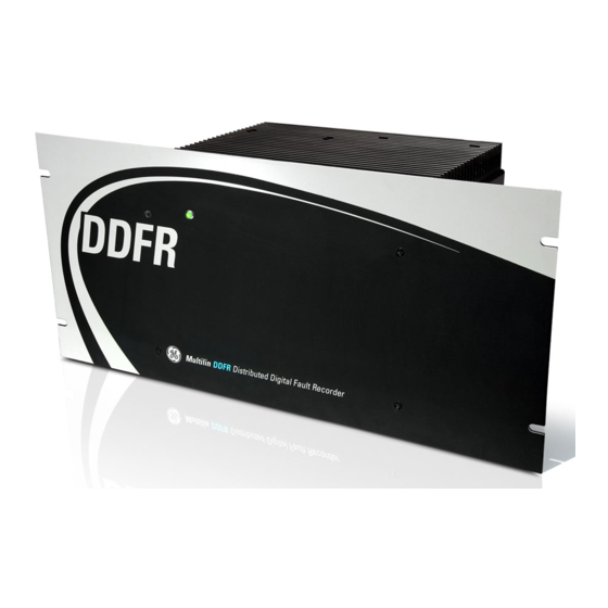
Page 13: The Physical Ddfr Unit
This single port is able to process these multiple inputs and outputs by connecting it to a port on an Ethernet switch such as the GE MultiLink switch. In short, the DDFR unit you have purchased, offers you the ability to configure your entire range of (DDFR-supported) relays and conveniently view and archive the fault information accumulated within these relays from the computer keyboard on your desk. - Page 14 ABOUT YOUR NEW DDFR UNIT CHAPTER 1: GETTING STARTED Dimensions DISTRIBUTED DIGITAL FAULT RECORDER – INSTRUCTION MANUAL...
-
Page 15: Installing The Enervista Ddfr Setup Program
Ethernet ports on this switch to the DDFR. • The EnerVista DDFR Setup Software has the same look and feel as the standard EnerVista setup programs used for programming GE Multilin protection relays such as the UR and SR families. See Figure 1-2 below. -
Page 16: Hardware Requirements - Ddfr Setup And Monitoring Software
1.3.3.1 EnerVista DDFR Setup After ensuring the above minimum hardware requirements are met, use the following procedure to install the DDFR software from the GE EnerVista CD. Insert the GE EnerVista CD into your CD-ROM drive. Click the Install Now button and follow the installation instructions to install the EnerVista Launchpad software on your local PC. - Page 17 CHAPTER 1: GETTING STARTED INSTALLING THE ENERVISTA DDFR SETUP PROGRAM Click the IED Setup button on the main EnerVista Launchpad screen, to open the IED Setup. Click the Add Product button to open the Add Product dialog: Click the from CD radio button at the top of the window. Select the DDFR from the Add Product window as shown above.
- Page 18 INSTALLING THE ENERVISTA DDFR SETUP PROGRAM CHAPTER 1: GETTING STARTED Once the DDFR Setup is installed, the DDFR icon will appear in the IED Setup window, as shown on the right hand side of figure 1-3 below. If at any time you are updating the DDFR software, select the “Web” radio button to ensure Note the most recent software release.
-
Page 19: Setting Up Computer-To-Ddfr Ethernet Communications
CHAPTER 1: GETTING STARTED SETTING UP COMPUTER-TO-DDFR ETHERNET COMMUNICATIONS Setting Up Computer-to-DDFR Ethernet Communications 1.4.1 Checking the Communications Setup in Your Computer Before proceeding with setting up computer-to-DDFR Ethernet communications, you must check the communications setup in your PC. New DDFRs are factory configured as follows: Note Table 1–2: Default DDFR IP Configuration IP Address... -
Page 20: Making The Initial Setup Connection
Ensure that the Ethernet cables are securely attached to both your computer and the Ethernet switch. Open the main EnerVista DDFR Setup screen by going into the GE Power Management folder in your computer Start menu. DISTRIBUTED DIGITAL FAULT RECORDER – INSTRUCTION MANUAL... - Page 21 CHAPTER 1: GETTING STARTED SETTING UP COMPUTER-TO-DDFR ETHERNET COMMUNICATIONS The DDFR is shipped from the Factory with the following default network parameters. Note These parameters must be reconfigured immediately to ensure that Network IP address conflicts do not occur. Table 1–3: Default DDFR IP Configuration IP Address Net Mask Gateway...
- Page 22 SETTING UP COMPUTER-TO-DDFR ETHERNET COMMUNICATIONS CHAPTER 1: GETTING STARTED When the DDFR Setup button is pressed, the Setup application will search to see if there is Note an unconfigured DDFR (ie: a DDFR containing a default IP address) connected on the local hub.
- Page 23 CHAPTER 1: GETTING STARTED SETTING UP COMPUTER-TO-DDFR ETHERNET COMMUNICATIONS Press GO. Press Yes to confirm the IP configuration. DISTRIBUTED DIGITAL FAULT RECORDER – INSTRUCTION MANUAL...
- Page 24 SETTING UP COMPUTER-TO-DDFR ETHERNET COMMUNICATIONS CHAPTER 1: GETTING STARTED The DDFR IP Address configuration is now changed. The DDFR Setup will automatically perform a clock synchronization. Press OK. The DDFR Setup screen will remain: If for any reason (firewall, network configuration, etc.) you cannot "Discover" a DDFR, you Note can manually add it into the DDFR environment using DDFR Setup, provided you know the IP Address of the DDFR unit.
- Page 25 CHAPTER 1: GETTING STARTED SETTING UP COMPUTER-TO-DDFR ETHERNET COMMUNICATIONS Enter the desired name in the DDFR Name field and a description (optional). Enter the IP Address of the DDFR. Click the Read Order Code button to connect to the DDFR and transfer the Order Code and firmware Version number from the DDFR.
- Page 26 SETTING UP COMPUTER-TO-DDFR ETHERNET COMMUNICATIONS CHAPTER 1: GETTING STARTED The new device will be added to the DDFR Site List located on the upper left side of the main EnerVista DDFR Setup screen. FIGURE 1–5: DDFR Site List (Online Window) DISTRIBUTED DIGITAL FAULT RECORDER –...
-
Page 27: Setting Up With Multiple Nic
CHAPTER 1: GETTING STARTED SETTING UP COMPUTER-TO-DDFR ETHERNET COMMUNICATIONS FIGURE 1–6: DDFR Site List (Online Window) Expanded The new DDFR unit has now been configured for Ethernet communication. 1.4.4 Setting up with Multiple NIC If your DDFR Setup cannot "Discover" the factory-configured DDFR unit, and you hav multiple NICs in your DDFR Setup computer, please proceed as follows: Select Control Panel >... - Page 28 SETTING UP COMPUTER-TO-DDFR ETHERNET COMMUNICATIONS CHAPTER 1: GETTING STARTED Note down your current TCP/IP configuration. If your current TCP/IP setting is static, note down your IP Address, Subnet Mask, and Default Gateway, as well as your Preferred and Alternate DNS servers. Click on the Use the following IP address radio button if you have a dynamic IP Address.
- Page 29 CHAPTER 1: GETTING STARTED SETTING UP COMPUTER-TO-DDFR ETHERNET COMMUNICATIONS Press the Discover DDFRs button. Once the Setup program has competed its routine, the window will show the discovered DDFRs and a warning window will appear, as shown below: Press Yes. DISTRIBUTED DIGITAL FAULT RECORDER –...
- Page 30 SETTING UP COMPUTER-TO-DDFR ETHERNET COMMUNICATIONS CHAPTER 1: GETTING STARTED The IP Address of the DDFR shown highlighted on the left side of the window, is the factory- installed IP Address, which has to be changed. At the top right side of the window, type a name and a description for the DDFR.
- Page 31 CHAPTER 1: GETTING STARTED SETTING UP COMPUTER-TO-DDFR ETHERNET COMMUNICATIONS Click on the Configure IP option When asked "Are you sure you want to change the DDFR’s IP Address configuration?", press the Yes button. The DDFR IP Configuration window shown above, will appear. Using the IP Address, Subnet Mask, and Default Gateway information given to you by your IT department, fill in this information on the IP Configuration window.
- Page 32 SETTING UP COMPUTER-TO-DDFR ETHERNET COMMUNICATIONS CHAPTER 1: GETTING STARTED When asked "Are you sure...", make sure you entered the correct IP Address, Subnet Mask, and Default Gateway information, then click the Yes button and change the IP setting in the DDFR. The system will attempt to connect to the DDFR using the new IP Address.
- Page 33 CHAPTER 1: GETTING STARTED SETTING UP COMPUTER-TO-DDFR ETHERNET COMMUNICATIONS On the main EnerVista DDFR Setup screen, click on the DDFR Setup button. The DDFR Setup window will appear: Highlight the DDFR you have just installed. Press the Delete button. The following Warning window will appear: DISTRIBUTED DIGITAL FAULT RECORDER –...
- Page 34 SETTING UP COMPUTER-TO-DDFR ETHERNET COMMUNICATIONS CHAPTER 1: GETTING STARTED Click on Yes. On the DDFR Setup screen, press the Discover DDFRs button. After a short time, a message window will appear indicating information about your discovered DDFR(s). DISTRIBUTED DIGITAL FAULT RECORDER – INSTRUCTION MANUAL...
- Page 35 CHAPTER 1: GETTING STARTED SETTING UP COMPUTER-TO-DDFR ETHERNET COMMUNICATIONS Click OK. Check out your DDFRs to ensure that none of them contain the original, factory-installed, IP Address. You can now go ahead and configure the new DDFR for the relays to which it will be connected.
-
Page 36: Using The Discover Ddfr Button
SETTING UP COMPUTER-TO-DDFR ETHERNET COMMUNICATIONS CHAPTER 1: GETTING STARTED 1.4.5 Using the Discover DDFR Button The Discover DDFR button allows you to automatically search out and add already configured DDFRs to the DDFR Site List (Online window). A message box will appear which indicates how many new DDFRs were found and how many were added to the system. - Page 37 CHAPTER 1: GETTING STARTED SETTING UP COMPUTER-TO-DDFR ETHERNET COMMUNICATIONS Press the DDFR Setup button at the top left of the EnerVista DDFR Setup screen. The DDFR Setup window will appear as shown: Note that in the above DDFR Setup window there are no DDFRs listed under the DDFR menu heading.
- Page 38 SETTING UP COMPUTER-TO-DDFR ETHERNET COMMUNICATIONS CHAPTER 1: GETTING STARTED In this example, three existing (but unlisted - "undiscovered") DDFRs appear in the DDFR Setup window, listed under the DDFR menu heading: FIGURE 1–7: "Discovering" new DDFRs If necessary, make adjustments to the DDFR Names and Descriptions.
- Page 39 CHAPTER 1: GETTING STARTED SETTING UP COMPUTER-TO-DDFR ETHERNET COMMUNICATIONS Expanding the DDFRs shows the configuration parameters: The newly set-up DDFRs are now ready to have their relay settings configured. For information on configuring DDFR relay settings, please refer to Chapter 3 of this Note manual.
-
Page 40: Setting Up Archiver Communication
SETTING UP COMPUTER-TO-DDFR ETHERNET COMMUNICATIONS CHAPTER 1: GETTING STARTED 1.4.6 Setting up Archiver Communication Click on the the DDFR Setup button to show the DDFR Setup window:. Click on the DDFR Archivers tree item. Click on the Add button. Fill in the Archiver’s IP Address. Press the Read Order Code button. - Page 41 CHAPTER 1: GETTING STARTED SETTING UP COMPUTER-TO-DDFR ETHERNET COMMUNICATIONS Assign the Archiver a new name, if desired. When complete, press the OK button to save the setup. If you do not have easy access to your Archiver (PC) IP Address, you can get it as follows: Note On the main Windows screen, select Start >...
-
Page 42: Setting Up Relay-To-Ddfr Communication
(sometimes known as "assets" - see below) installed in your facility, you may have to use a converter - GE Multilin’s MultiNet converter, for example - to convert to Ethernet from a variety of other communication types. Once all communication types... -
Page 43: Attaching Rs485-Based Relays
CHAPTER 1: GETTING STARTED SETTING UP RELAY-TO-DDFR COMMUNICATION 1.5.1.2 Attaching RS485-based Relays FIGURE 1–9: Typical RS485-based DDFR-to-Relay Communications DISTRIBUTED DIGITAL FAULT RECORDER – INSTRUCTION MANUAL... -
Page 44: Attaching Rs232-Based Relays
SETTING UP RELAY-TO-DDFR COMMUNICATION CHAPTER 1: GETTING STARTED 1.5.1.3 Attaching RS232-based Relays FIGURE 1–10: Typical RS232-based DDFR-to-Relay Communications 1.5.1.4 Attaching Multiple Relay Communication Types to the DDFR FIGURE 1–11: Typical DDFR-to-Relay Mixed Communications DISTRIBUTED DIGITAL FAULT RECORDER – INSTRUCTION MANUAL... -
Page 45: 2: Product Overview
GE Consumer & Industrial Multilin Distributed Digital Fault Recorder Chapter 2: Product Description Product Description Overview 2.1.1 Benefits of Distributed vs Centralized Digital Fault Recording Figures 2-1 and 2-2 show the substation wiring method, data collection, and communication architecture for a centralized Digital Fault Recorder versus that of a Distributed Digital Fault Recorder. -
Page 46: Centralized Dfr System
FIGURE 2–1: Centralized Digital Fault RecorderSystem 2.1.1.2 Distributed DFR System (DDFR) In the distributed DFR (DDFR) the data recording facilities already built into the GE Multilin protection relays, record all information. This data is retrieved by the station DDFR(s) and stored and processed for analysis. -
Page 47: Features Of The Ge Multilin Ddfr System
2.1.2 Features of the GE Multilin DDFR System The GE Multilin DDFR system collects events, oscillography and data logger files from the data recording facilities built into your already installed UR, SR, and F650 relays (see chapter 5), and stores them for later viewing in the PC-based DDFR Archiver. -
Page 48: The Ddfr Archiver
DDFRs distributed throughout the power system,. This tool provides you with a single convenient location from which to analyze power system events gathered from DDFRs connected to GE Multilin protection relays. DISTRIBUTED DIGITAL FAULT RECORDER – INSTRUCTION MANUAL... -
Page 49: Ge Multilin Relay Firmware Support
CHAPTER 2: PRODUCT DESCRIPTION GE MULTILIN RELAY FIRMWARE SUPPORT GE Multilin Relay Firmware Support 2.2.1 DDFR-Supported Relay Firmware Versions Relay Series Relay Firmware Level(s) Supported 750/760 3.6x - 7.0x 2.5x - 5.0x 2.4x - 5.0x 1.3x - 4.0x 2.6x - 5.2x 3.0x - 4.9x... -
Page 50: Specifications
SPECIFICATIONS CHAPTER 2: PRODUCT DESCRIPTION Specifications The DDFR is a stand-alone data management device suitable for substation environments, which records all station disturbances without the need for any additional hardware or software products. Specfications are subject to change without notice. Note 2.3.1 Hardware Specifications... -
Page 51: Test Specifications
CHAPTER 2: PRODUCT DESCRIPTION SPECIFICATIONS Voltage Loss Holdup:........LOW RANGE: 10 ms at 24 VDC 35 ms at 48 VDC HIGH RANGE: 85 ms at 125 VDC 300 ms at 220 VDC Power consumption:........30 W 2.3.2 Test Specifications PRODUCTION TESTS Dielectric Strength: ........2500 VDC ELECTROMAGNETIC COMPATIBILITY IMMUNITY Power supply and outputs:......2.5 kV common mode 1.0 kV differential mode... -
Page 52: Environmental Specifications
SPECIFICATIONS CHAPTER 2: PRODUCT DESCRIPTION TEMPERATURE Cold: ..............IEC 60068-2-1 Test Ad: ...............-40 ºC, 16 hours Dry Heat: ............IEC 60068-2-2 Test Bd: ...............+75ºC, 16 hours Damp Heat Cyclic: ........IEC 60068-2-30 Test Db: ..............95% r.h., 25º to 55º, 6 cycles MECHANICS Vibrations: ............IEC 60255-21-1 Envelope: ............Class 2 Shock and Bump: .........IEC 60255-21-2 Envelope: ............Class 1... - Page 53 CHAPTER 2: PRODUCT DESCRIPTION SPECIFICATIONS EN/IEC60255-22-6:2001 10Vrms Am 80% Conducted RF Immunity 150Khz -80 MHz / EN/IEC1000-4-6:1996 EN/IECIEC61000-4- Power Frequency Magnetic Field Immunity 30A/m 8:1993 Pulse Magnetic Field immunity EN/IEC61000-4-9:1994 1000A/m Conducted Emissions EN 61000-6-4:2001) EN/IEC 60255-25:2000 & Class A CISPR22 ETP 6.2 -6.7 Radiated Emissions EN 61000-6-4:2001)
- Page 54 SPECIFICATIONS CHAPTER 2: PRODUCT DESCRIPTION DISTRIBUTED DIGITAL FAULT RECORDER – INSTRUCTION MANUAL...
-
Page 55: 3: Ddfr Configuration Configuration Options
GE Consumer & Industrial Multilin Distributed Digital Fault Recorder Chapter 3: DDFR Configuration DDFR Configuration Configuration Options 3.1.1 Configuration - An Explanation Having set up your DDFR(s) for Ethernet communication, the next stage is to configure the settings of the DDFR(s) - that is, set up an environment that will allow each DDFR to communicate with all the relays ("devices") connected to it. -
Page 56: Setting Up Your Password
• an indirect connection - the DDFR connected to an existing system, and the configuring computer connected to this system via a (GE MultiLink) switch. The latter is the more convenient approach. 3.1.4.2 Multiple DDFR Units... -
Page 57: Fresh" And "Preset" Configuring
CHAPTER 3: DDFR CONFIGURATION CONFIGURATION OPTIONS Again, the latter is the more convenient approach. 3.1.4.3 "Fresh" and "Preset" Configuring In both of the above configuration situations, you can transfer configuration parameters to each of the DDFRs using either, • new "fresh" individual parameters; parameters that you can transfer immediately - parameter by parameter - to each DDFR unit, or •... -
Page 58: Using Enervista Ddfr Setup Software
USING ENERVISTA DDFR SETUP SOFTWARE CHAPTER 3: DDFR CONFIGURATION Using EnerVista DDFR Setup Software 3.2.1 The EnerVista DDFR Menu Bar The EnerVista DDFR Setup Software menu bar layout is similar to that used by all EnerVista Setup applications. FIGURE 3–1: EnerVista DDFR Setup Software Menu Bar 3.2.2 Enervista DDFR Online and Offline Window Structures DDFR Online... -
Page 59: The Ddfr Online Window Menu
CHAPTER 3: DDFR CONFIGURATION USING ENERVISTA DDFR SETUP SOFTWARE 3.2.3 The EnerVista DDFR Online Window (Site List) The DDFR Online Window, is shown below: The Online Window has been expanded to show the menu for one particular DDFR device, called "Substation 1." Immediately below, we describe the DDFR Online window menu components. - Page 60 USING ENERVISTA DDFR SETUP SOFTWARE CHAPTER 3: DDFR CONFIGURATION FIGURE 3–4: The Device Definition Menu • The Settings menu contains all the menu items and settings required for setting up the DDFR to retrieve records from the protection relays in the station, and for setting up appropriate watchdogs in the DDFR.
- Page 61 CHAPTER 3: DDFR CONFIGURATION USING ENERVISTA DDFR SETUP SOFTWARE • Clear Data: Click to clear event/waveform/datalog already collected in DDFR unit. • Reset DDFR: Click to force a DDFR system reboot. Before clicking on Clear Data, make sure you have archived the information contained Note in the DDFR, using the DDFR Archiver, as all the event/waveform/datalog will be deleted.
- Page 62 USING ENERVISTA DDFR SETUP SOFTWARE CHAPTER 3: DDFR CONFIGURATION FIGURE 3–7: The Actual Values Menu • The Maintenance menu contains a method for updating the firmware on the DDFR and for changing the IP Address configuration. • Configure IP: Click to change the IP address of the DDFR. •...
-
Page 63: The Ddfr Archivers Online Window Menu
CHAPTER 3: DDFR CONFIGURATION USING ENERVISTA DDFR SETUP SOFTWARE 3.2.3.2 The DDFR Archivers Online Window Menu Before this section of the DDFR Online window can be used, the Archiver has to be set up. This is described in 1.4.6: Setting up Archiver Communication. Once Archiver communication has been set up, and the Archiver itself is online, when the DDFR Archivers menu is expanded as shown, the Device Definition is displayed in much the same way as the DDFR itself. - Page 64 USING ENERVISTA DDFR SETUP SOFTWARE CHAPTER 3: DDFR CONFIGURATION Selecting Events, brings up the Archiver Sequence of Events screen in a separate window Note (see section 5), whereas when Waveforms and Data Logger are selected, a list is displayed on the right hand window of the main DDFR screen. DISTRIBUTED DIGITAL FAULT RECORDER –...
-
Page 65: Configuring Ddfr Settings Files
CHAPTER 3: DDFR CONFIGURATION CONFIGURING DDFR SETTINGS FILES Configuring DDFR Settings Files 3.3.1 What is a Settings File? The DDFR Settings File - identified by its .DFR suffix - contains information on all the relays associated with that particular DDFR. When a Settings File is accessed by clicking on the Device Setup line in either the Online or Offline window (see figure 3-2), it is found to contain the following information: FIGURE 3–9: Contents of a Typical DDFR Settings File... -
Page 66: Creating A New Settings File
CONFIGURING DDFR SETTINGS FILES CHAPTER 3: DDFR CONFIGURATION DDFRs are usually organized and grouped by relay-side communication interfaces (eg: Ethernet, RS485, etc.) and each DDFR may communicate with a maximum of 50 relays selected from the SR, UR or F650 product series. The EnerVista DDFR Setup Software interface supports two ways of handling changes to DDFR-relay settings: •... -
Page 67: Adding Relays To Addfr S
CHAPTER 3: DDFR CONFIGURATION CONFIGURING DDFR SETTINGS FILES To select a file name and path for the new file, click the button to the right of the Path box. Select (or create) the folder name and path where you want to store the file, or select any displayed file name if you simply want to update an existing file. -
Page 68: Upgrading Settings Files To A
CONFIGURING DDFR SETTINGS FILES CHAPTER 3: DDFR CONFIGURATION Click on Add Device. Give the new relay ("device") an appropiate name. Fill in the rest of the configuration parameters. Only when you fill in the communications information and the Device Type in online mode, Note will the system contact the relay in question and automatically transfer the Order Code and Version. -
Page 69: Transferring And Savings
CHAPTER 3: DDFR CONFIGURATION CONFIGURING DDFR SETTINGS FILES Click the tab on the (firmware) Version drop-down menu to view the list of Version Numbers. Select the desired firmware Version Number. When complete, click OK to convert the Settings File to the desired DDFR firmware revision. - Page 70 CONFIGURING DDFR SETTINGS FILES CHAPTER 3: DDFR CONFIGURATION In the Offline Window, right-click on ‘Files’ and select the Add Existing Setting File item as shown: The Open dialog box will appear, prompting you to select a previously saved (but ® not yet listed) Settings File.
-
Page 71: Printing Settings And Actual
CHAPTER 3: DDFR CONFIGURATION CONFIGURING DDFR SETTINGS FILES If the versions are not identical, see Upgrading Settings Files to a New DDFR Firmware Revision - section 3.2.4 - for details on changing the Settings File Version. Fully expand the Settings File. Click on the Send file to DDFR menu item. - Page 72 CONFIGURING DDFR SETTINGS FILES CHAPTER 3: DDFR CONFIGURATION From the main window, select the File > Print Preview Settings menu item. The printable sheet containing the content of the Settings File for that DDFR will appear in the Device View window on the right hand side of the main screen, as shown Select Print, Zoom or Close from the menu buttons at the top of this window.
-
Page 73: Configuring The Ddfr Watchdogs
CHAPTER 3: DDFR CONFIGURATION CONFIGURING THE DDFR WATCHDOGS Configuring the DDFR WatchDogs A Watchdog is essentially a "health monitor" for the DDFR. Note For a full explanation, see below. FIGURE 3–10: DDFR WatchDogs Screen The DDFR WatchDogs Screen (figure 3-10) can be accessed using the Settings > WatchDogs menu option in the Online Device Tree, as shown in Figure 3-11. -
Page 74: Types Of Watchdog
CONFIGURING THE DDFR WATCHDOGS CHAPTER 3: DDFR CONFIGURATION question. Similarly, WatchDog information can be directly transferred to the DDFR and transferred to the appropriate Settings File - using the Update File from DDFR command, as shown below. 3.4.1 Types of WatchDog The DDFR contains three different types of WatchDog, or "health monitor": Internal (DDFR) WatchDog Takes corrective action to ensure that the DDFR application is continually running. -
Page 75: The Drivespace Watchdog
CHAPTER 3: DDFR CONFIGURATION CONFIGURING THE DDFR WATCHDOGS 3.4.3 The DriveSpace WatchDog The DDFR has a DriveSpace WatchDog that alerts you that internal storage space in the DDFR is reaching capacity. • When the storage space in DDFR reaches a certain preset level (defaulted to 75% of record storage capacity), the DDFR sends an alert to protection relays connected to the network. -
Page 76: Adding A Drivespace Watchdog
CONFIGURING THE DDFR WATCHDOGS CHAPTER 3: DDFR CONFIGURATION Perform automated maintenance when 'Used Space' capacity of Local Disk exceeds 80% When the DDFR’s used storage space exceeds this level, the automated maintenance starts deleting the oldest records. Automated maintenance occurs until 'Used Space' capacity of Local Disk drops below 70% This setting indicates the level of used storage space that the DDFR will recover to before the automated maintenance stops. - Page 77 CHAPTER 3: DDFR CONFIGURATION CONFIGURING THE DDFR WATCHDOGS Note that because Virtual Inputs are used only on GE UR Series relays only, non-UR Note relays are NOT listed in the Device column.. FIGURE 3–14: List of Virtual Inputs on Receiving Device (relay)
- Page 78 CONFIGURING THE DDFR WATCHDOGS CHAPTER 3: DDFR CONFIGURATION DISTRIBUTED DIGITAL FAULT RECORDER – INSTRUCTION MANUAL...
-
Page 79: Relay Information
GE Consumer & Industrial Multilin Distributed Digital Fault Recorder Chapter 4: The DDFR and Relay Information The DDFR and Relay Information Relay Information 4.1.1 Actual Values Records in the DDFR Setup Program The records captured by the DDFR can be viewed in two different ways. The first is through the Actual Values menu item in the DDFR Setup program (see chapter 3 of this manual) and the second is through the DDFR Archiver. -
Page 80: Viewing Waveform Records
RELAY INFORMATION CHAPTER 4: THE DDFR AND RELAY INFORMATION 4.1.1.1 Viewing Event Records Double-Click on the Actual Values > Events tree item . The Event record stored in the DDFR appears, and is displayed in the Main window. FIGURE 4–2: Event Viewer 4.1.1.2 Viewing Waveform Records Double-Click on the Actual Values >... -
Page 81: Viewing Data Logger Records (Ur Relays Only)
CHAPTER 4: THE DDFR AND RELAY INFORMATIONRELAY INFORMATION FIGURE 4–3: Waveform File in COMTRADE Viewer The Toolbar, located on the left, near the top of the window, contains the following buttons: Open File Save As Print DDFR Setup Preferences Play Stop 4.1.1.3 Viewing Data Logger Records (UR Relays Only) DataLogger Records are in all respects the same as Waveform Records, the only difference Note... -
Page 82: View Archiver Actual Values
RELAY INFORMATION CHAPTER 4: THE DDFR AND RELAY INFORMATION Click on one of the Data Logger records listed here to open the file in a COMTRADE viewer. FIGURE 4–4: Waveform/Data Logger File Browser Window 4.1.1.4 View Archiver Actual Values For information on how to use DDFR Setup to view events, waveforms, and dataloggers archived in any archiver system, please refer to section 3.2.3.2: The DDFR Archivers Online Window Menu. -
Page 83: Configuring The External Watchdog
CHAPTER 4: THE DDFR AND RELAY INFORMATIONCONFIGURING THE EXTERNAL WATCHDOG Configuring the External WatchDog A Watchdog is essentially a "health monitor" for the DDFR. For a full explanation, see Note below. The DDFR WatchDog settings, including those of the External Watchdog, can be found by clicking the Settings >... -
Page 84: Types Of Watchdog
CONFIGURING THE EXTERNAL WATCHDOG CHAPTER 4: THE DDFR AND RELAY INFORMATION 4.2.1 Types of WatchDog As indicated in Chapter 3, The DDFR contains three different types of WatchDog, or "health monitor": Internal (DDFR) WatchDog Takes corrective action to ensure that the DDFR application is continually running. If the DDFR application is NOT running for some reason, the Internal Watchdog will attempt to fix the situation, by, for example, restarting the application. -
Page 85: Adding An External Watchdog
Virtual Input pull-down list as shown in Figure 3- 14.. FIGURE 4–8: List of Virtual Inputs on Receiving Device (relay) Note that because Virtual Inputs are used only on GE UR Series relays only, non-UR Note relays are NOT listed in the Device column. -
Page 86: Configuring Ur Relays For Virtual Input (Vi) Commands
CONFIGURING THE EXTERNAL WATCHDOG CHAPTER 4: THE DDFR AND RELAY INFORMATION Similarly, select the Type of WatchDog to be used (External or DriveSpace) on the device selected, by clicking on the Type pull- down list as shown in Figure 3-15. FIGURE 4–9: List of Types of WatchDog The same Virtual Input on a UR device cannot be used as both an External WatchDog and Note... -
Page 87: Flexlogic
CHAPTER 4: THE DDFR AND RELAY INFORMATIONCONFIGURING THE EXTERNAL WATCHDOG The above settings screen shows a UR device configured to receive an External WatchDog at VI 8 and a DriveSpace Watchdog at VI 9. The Function setting must be enabled and the Type setting is set to Self-Reset. The Virtual Input Name is changed to reflect the type of WatchDog being received. - Page 88 CONFIGURING THE EXTERNAL WATCHDOG CHAPTER 4: THE DDFR AND RELAY INFORMATION DISTRIBUTED DIGITAL FAULT RECORDER – INSTRUCTION MANUAL...
-
Page 89: The Ddfr Archiver
- provides you with a single base (your computer) from which to view and analyze power system events that have occurred anywhere a DDFR is located and is connected to GE Multilin protection relays - the primary data collection units. -
Page 90: Archiver Features
THE DDFR ARCHIVER CHAPTER 5: RETRIEVING AND VIEWING DDFR ARCHIVER DATA While the Archiver can be based in a local (on-site) computer, it is usually based in a Note remote (off-site) location in order to fully centralize the gathering of data from DDFR units in all the separate physical locations (see figure 5.1). -
Page 91: Ddfr Archiver Installation
Root Folder, which you can configure (see section 5.2.3 below). The Root Folder is defaulted to: C:\Documents and Settings\All Users\Documents\GE Power Management\DDFRArchiver\Data\Below the Root Folder, a separate folder is created for each DDFR. Each folder name uses the exact name of a DDFR. -
Page 92
THE DDFR ARCHIVER CHAPTER 5: RETRIEVING AND VIEWING DDFR ARCHIVER DATA
\DataLoggers: Contains the CFG and DAT files created for each DataLogger record generated by a UR relay. The Dataloggers files use the following naming convention: -yyyymmdd-hhmmss-DLR.cfg -yyyymmdd-hhmmss-DLR (DAT file) \Events: Contains the CSV files that hold the backed-up events from the SQL database. -
Page 93: Structure Configuring The Ddfr Archiver
CHAPTER 5: RETRIEVING AND VIEWING DDFR ARCHIVER DATA CONFIGURING THE DDFR ARCHIVER Configuring the DDFR Archiver 5.2.1 General Configuring the DDFR Archiver can be done using one of two methods, as shown below. To begin, Open the DDFR Archiver. FIGURE 5–2: DDFR Archiver Main Screen Showing Tools Menu (top) Select Tools >... -
Page 94: Archiver Configuration Method 1
CONFIGURING THE DDFR ARCHIVER CHAPTER 5: RETRIEVING AND VIEWING DDFR ARCHIVER DATA 5.2.1.1 Archiver Configuration Method 1 If all the DDFRs are within the local network, Press the Discover DDFR button (see section 5.2.4) to have the DDFR Archiver attempt to locate all the DDFRs on the network. Any DDFRs discovered that are not already known to the DDFR Archiver are added to the environment. -
Page 95: Archiver Record Storage
CHAPTER 5: RETRIEVING AND VIEWING DDFR ARCHIVER DATA CONFIGURING THE DDFR ARCHIVER 5.2.2.1 Archiver Record Storage This field sets the directory path where all the information retrieved from the DDFRs is stored. The DDFR Archiver creates a separate folder for each of the configured DDFRs, as detailed in section 5.1.3. -
Page 96: Viewing Data In The Ddfr Archiver
VIEWING DATA IN THE DDFR ARCHIVER CHAPTER 5: RETRIEVING AND VIEWING DDFR ARCHIVER DATA Viewing Data in the DDFR Archiver 5.3.1 Archiver Records - General As shown in section 5.2.3 above, you can set the location for accessing the data stored on your computer by the DDFR Archiver. - Page 97 CHAPTER 5: RETRIEVING AND VIEWING DDFR ARCHIVER DATA VIEWING DATA IN THE DDFR ARCHIVER • Event – This field includes the ID tag that was programmed into the relay (i.e. If you renamed "Contact Input 1" to “Breaker 52A”, the Event field should show "Breaker 52A".) •...
- Page 98 VIEWING DATA IN THE DDFR ARCHIVER CHAPTER 5: RETRIEVING AND VIEWING DDFR ARCHIVER DATA Toolbar – Click these control buttons to activate the most-often-used commands. Unacknowledged Refresh Alarms About Viewer Configuration Sequence of Alarms System Waveform Events Device Events Status Bar – The status bar is located at the bottom of the main window and provides messages about Event/Alarm Viewer's current status, such as the presence of unacknowledged alarms.
-
Page 99: Archiver Waveforms Records
CHAPTER 5: RETRIEVING AND VIEWING DDFR ARCHIVER DATA VIEWING DATA IN THE DDFR ARCHIVER Select File > Configure from the Events Screen main menu. FIGURE 5–7: Configuring the Data Display Default Window From the Available Windows section, select the Window that you want to bring up when you open the Archiver Events Screen. -
Page 100: Waveform File Access
VIEWING DATA IN THE DDFR ARCHIVER CHAPTER 5: RETRIEVING AND VIEWING DDFR ARCHIVER DATA 5.3.3.1 Waveform File Access Click on View A Windows Open dialog box appears. Note that the path shown on the right side of the dialog box is the default path discussed in section 5.1.3. -
Page 101: Waveform Merge
CHAPTER 5: RETRIEVING AND VIEWING DDFR ARCHIVER DATA VIEWING DATA IN THE DDFR ARCHIVER For Waveform file naming conventions see section 5.1.3. Note Choose a Waveform file and double-click on it. The file opens in a COMTRADE viewer as shown in Figure 5-8. FIGURE 5–9: Archived Waveform Event COMTRADE File The Toolbar, located on the left, near the top of the window, contains the following buttons: Open File... - Page 102 VIEWING DATA IN THE DDFR ARCHIVER CHAPTER 5: RETRIEVING AND VIEWING DDFR ARCHIVER DATA On the Archiver Waveform menu, click on Merge. Click Add button to add waveform files to be merged. Select the COMTRADE files you wish to merge or combine by clicking on the browse (...) buttons on the right side of the selection boxes.
-
Page 103: Waveform Resample
CHAPTER 5: RETRIEVING AND VIEWING DDFR ARCHIVER DATA VIEWING DATA IN THE DDFR ARCHIVER Continue the process, pressing Next each time, until the merge process is complete. 5.3.3.3 Waveform Resample On the Archiver Waveform Menu, click on Resample. Follow a procedure similar to Merge above. 5.3.3.4 Viewing Retrieved Waveform Files The Waveform Viewer feature within the DDFR Archiver provides a visual display of power systems data and relay operation data captured during a specific triggered event. -
Page 104: Waveform Cursor Times
VIEWING DATA IN THE DDFR ARCHIVER CHAPTER 5: RETRIEVING AND VIEWING DDFR ARCHIVER DATA Waveform records are stored in folders on the local drive categorized first by the DDFR name. A folder is created for each DDFR. Waveform file names are based on the Device Name, followed by the date, then followed by the time of the capture. -
Page 105: Viewing Phasors
CHAPTER 5: RETRIEVING AND VIEWING DDFR ARCHIVER DATA VIEWING DATA IN THE DDFR ARCHIVER 5.3.3.6 Viewing Phasors To Open the Phasors window: Click on the Phasors button in the Toolbar near the top of the Waveform window. A new window will open displaying a Phasor Diagram as seen in Figure 5-12. - Page 106 VIEWING DATA IN THE DDFR ARCHIVER CHAPTER 5: RETRIEVING AND VIEWING DDFR ARCHIVER DATA The Phasor Diagram indicates the rotation, magnitude and angle with respect to a selected reference component chosen in the COMTRADE Preferences window, shown in Figure 5-13, below. You can access this Preferences window by clicking the Preferences button indicated in Figure 5-12, above.
-
Page 107: Viewing Harmonics
CHAPTER 5: RETRIEVING AND VIEWING DDFR ARCHIVER DATA VIEWING DATA IN THE DDFR ARCHIVER Scaled vs. Fixed: Select between scaled phasors or fixed magnitude phasors. Fixed magnitude phasors will ignore the magnitude value and will only show the angles. The actual values for the phasor quantities such as amplitude and phase angle, are displayed above the phasor diagram as shown below.: FIGURE 5–15: Waveform Phasor Actual Values The Preferences Button displays the Preferences screen that can be used to change the... -
Page 108: Archiver Data Logger Records
VIEWING DATA IN THE DDFR ARCHIVER CHAPTER 5: RETRIEVING AND VIEWING DDFR ARCHIVER DATA The following options are available within the Harmonics viewing window: Select between cursor positions. This is done by clicking on the tabs cursor tabs as seen in Figure 4-12: FIGURE 5–17: Waveform Cursor Positions A table listing the calculated percentage of THD (Total Harmonic Distortion) for each phase... - Page 109 CHAPTER 5: RETRIEVING AND VIEWING DDFR ARCHIVER DATA VIEWING DATA IN THE DDFR ARCHIVER On the DDFR Archiver Main Screen, click the Data Logger menu item. A Windows Open dialog box appears. Note that the path shown on the right window of the dialog box is the default path discussed in section 5.1.3.
-
Page 110: Viewing The Retrieved Data Logger Files
VIEWING DATA IN THE DDFR ARCHIVER CHAPTER 5: RETRIEVING AND VIEWING DDFR ARCHIVER DATA This screen lists all the Events that were recorded and archived by that DDFR to the Archiver. The Events are itemized both by the UR relays which recorded them and by the date and time on which each Event occurred in that relay. - Page 111 CHAPTER 5: RETRIEVING AND VIEWING DDFR ARCHIVER DATA VIEWING DATA IN THE DDFR ARCHIVER The Data Logger file names are based on the Device Name, followed by the date and are followed by the time of the capture, as detailed in section 5.1.3. For example, if the device name is D60_1, the capture date is March 6, 2006 and the time is 12:04.52 AM or 00:04.52, the file is displayed as: D60_1-20060306-000452.CFG...
- Page 112 VIEWING DATA IN THE DDFR ARCHIVER CHAPTER 5: RETRIEVING AND VIEWING DDFR ARCHIVER DATA DISTRIBUTED DIGITAL FAULT RECORDER – INSTRUCTION MANUAL...
-
Page 113: 6: Miscellaneous Change Notes
GE Consumer & Industrial Multilin Distributed Digital Fault Recorder Chapter 6: Miscellaneous Miscellaneous Change Notes 6.1.1 Revision History Manual part no. Revision Release date 1601-9024-A1 1.0x July 10, 2007 1601-9024-A2 1.0x August 24, 2007 6.1.2 Changes to the DDFR Manual Table 6–1: Major updates for DDFR manual revision A2... - Page 114 CHANGE NOTES CHAPTER 6: MISCELLANEOUS Table 6–1: Major updates for DDFR manual revision A2 Page (A1) Page (A2) Change Description Section 3.2.3.1, changed to - Reset DDFR: Click to force a DDFR system reboot Section 3.2.3.1, explaination clarified: Most recent 300-500 events per device, depending on number of devices configured Most recent 10-50 waveforms per device, depending on number of devices configured...
- Page 115 INDEX Index Index Actual Values ....................4-71 Data Logger Records ..................4-73 DDFR ......................... 3-61 "health monitor" ..................3-65, 4-75 actual values menu ..................3-53 Archiver function ..................... 2-39 commands menu ..................... 3-52 communication to relays, setting up ............... 1-34 configuration parameters ................
- Page 116 INDEX Setup button ....................1-29 site list ................... 1-19, 1-30, 3-51 supported relay firmware versions ..............2-41 use of EnerVista with ..................1-7 DDFR ARCHIVER function ......................2-40 DDFR Configuration Parameters ..............1-31 DDFR Read Order Code button ..............1-30 DDFR SETTINGS FILES .......................
- Page 117 INDEX ICONS caution ......................1-2 danger ......................1-2 note ........................1-2 MANUAL using ......................... 1-4 ORDERING ......................1-1 PASSWORD ......................... 3-47 Administrators ....................3-47 Engineers ......................3-47 Setup ....................... 3-48 SOFTWARE installation ......................1-8 DISTRIBUTED DIGITAL FAULT RECORDER – INSTRUCTION MANUAL...
- Page 118 INDEX Virtual Input ..................... 4-77 Virtual Input Commands ................4-78 Waveform Records ..................4-72 DISTRIBUTED DIGITAL FAULT RECORDER – INSTRUCTION MANUAL...