Table of Contents
Quick Links
Table of Contents

Related Manuals for GE SymNet1

Summary of Contents for GE SymNet1
- Page 1 SymNet1 User Manual...
- Page 2 Software. 1. Definitions. The following definitions apply to this document: a. “GE SECURITY”, with respect to title to or warranty of the Software, means GE Security Inc., a Delaware corporation. b. “Software” means SymNav, the executable software or firmware programs and accom-...
- Page 3 Software to a human-perceivable form, nor create derivative works or programs based on the Software. 5. Limited warranty. GE SECURITY warrants that for one (1) year from the date of delivery of the Licensed Product (Software Warranty Period), the functions contained in the Software will...
- Page 4 You further agree that this agreement is the complete and exclusive statement of the agreement between You and GE SECURITY, and supersedes any proposal or prior agreement, oral or written, and any other communication relating to the subject matter of this agreement.
-
Page 5: Table Of Contents
SymNet1 connectors and indicators ........ - Page 6 SymNet1 User Manual Chapter 5. Technical specifications ..........41 Technical specifications.
-
Page 7: Preface
Preface This is the GE SymNet1 User Manual for model SymNet1-5RC. This document includes an overview of the product and detailed instructions explaining: • how to install and configure; and • how to connect to other GE IP devices. There is also information describing how to contact technical support if you have questions or concerns. - Page 8 SymNet1 User Manual...
-
Page 9: Overview
Chapter 1 Overview This chapter provides an overview of your SymNet1, including features, product contents, installation environment, and default IP addresses. In this chapter: Product description......... . 2 Features . -
Page 10: Product Description
User Manual Product description The GE SymNet1-5RC is a small footprint video streaming unit that is used for video monitoring and surveillance over IP networks. It uses MPEG-4 compression technologies to deliver high quality video, audio, and data over 10/100 Base-T networks. The SymNet1’s basic function is to either encode analog video (NTSC) to MPEG-4 digital video or decode MPEG-4 digital video to analog video. -
Page 11: Product Contents
Chapter 1 Overview Product contents The SymNet1 system consists of the following: • SymNet1 • SymNet1 User Manual • SymNav software CD • 12 VDC 1.33 amp power supply • 20-way 2-row terminal block connector • three-position connector • RS-232 serial cable Check the package and contents (Figure 1) for visible damage. -
Page 12: Installation Environment
User Manual Installation environment You should consider the following environmental elements when installing the SymNet1: Power: Ensure that the site's AC power is stable and within the rated voltage of the external power supply. If the site's AC power is likely to have spikes or power dips, use power line conditioning or an uninterruptible power supply (UPS). -
Page 13: Passwords
Yes, through the webserver. admin Log In password SymNav Yes, through the Security 12345 menu. Default IP addresses The SymNet1 comes with the following preset IP addresses: • IP address of 192.168.1.12 • Subnet mask of 255.255.255.0 • Gateway address of 192.168.1.1 Note: These IP addresses should be changed before you connect to your IP network. -
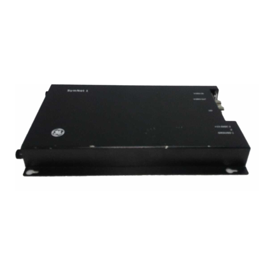
Page 14: Symnet1 Connectors And Indicators
I/O port Connectors SymNet1 connectors include: Power connector. Connects the external power supply to the SymNet1-5RC. I/O connector. Connects alarm, audio, RS-232, RS-485 input and output. Video I/O connector. Input and output connection of two composite video signals through two separated BNC connectors. -
Page 15: Installation
Chapter 2 Installation This chapter provides information on installing your SymNet1, including wiring connections and instructions on setting the IP address. In this chapter: Power connections ......... . 8 IP address setting . -
Page 16: Power Connections
5. Supply power to the unit by plugging the power supply into a properly rated power source. The power LED illuminates to show that the SymNet1 is receiving power. If it does not illuminate, check the terminal block connections and the power source. -
Page 17: Ip Address Setting
Installation IP address setting In order to use the SymNet1 correctly you must change the IP addresses from the defaults to ones that your specific network will recognize. This requires a serial cable (provided) and a connection to a PC. -
Page 18: Hyperterminal
10. Enter the new IP addresses and then press Enter. Note: Obtain your network specific IP addresses from your network administrator. 11. After the Gateway address is entered the SymNet1 will reboot. 12. Remove power from the SymNet1 and disconnect the serial cable from your PC. -
Page 19: General Connections
Chapter 2 Installation General connections Use Figure 6 as a guide to connect the various peripherals to the connections on the SymNet1. Figure 6. Connection diagram Speaker with amp Alarm I/O PC with SymNav (line-level audio out) and RS-484 RS-232... -
Page 20: Audio And Alarm Connections
2. Connect a wire from pin 12 (TX-) to pin 14 (RX-) on the 20-pin terminal block. 3. Connect a wire from the RS-485+ pin on the DVMRe or KTD-405 to pin 11 or 13 on the SymNet1 terminal block. -
Page 21: Webserver
Chapter 3 WebServer This chapter provides an overview of the SymNet1 WebServer and instructions on changing WebServer settings and options. In this chapter: WebServer overview ........14 SymBrowser page . -
Page 22: Webserver Overview
SymNet1. The default IP address from the factory is 192.138.1.12. To get the SymNet1 to stream video, at a minimum the Streaming settings must be configured. To access the web interface, do the following: 1. -
Page 23: Symbrowser Page
Chapter 3 WebServer SymBrowser page Click the SymBrowser link to launch the SymBrowser page (Figure 9). The SymBrowser page provides access to live and recorded video without the need for additional software. Simply type in the unit’s IP address and click the Connect button. -
Page 24: Configuration Page
User Manual Configuration page Click the Configure link to launch the Configuration page (Figure 10). Figure 10. Configuration page The Configuration page allows you to remotely modify the following settings of the SymNet1: • Network settings (see Network settings on page 17) •... -
Page 25: Network Settings
WebServer Network settings The Network settings page (Figure 11) provides an alternate method of changing the SymNet1’s IP addresses. You can also enable dynamic host configuration protocol (DHCP) and assign your unit a hostname. DHCP is an Internet protocol for automating the configuration of devices that use TCP/IP. You can use DHCP to automatically assign IP addresses. -
Page 26: Streaming Settings
IP Camera, or SymNet1 (Encoder). A UDP receiver is typically a SymDec-1, SymNav software, or a SymDec- 4, which can display and record the streamed video. The SymNet1 (Decoder) can also be setup as a receiver, but it can only display the streamed video since it does not have recording capability. - Page 27 SymNav software is the next generation of software that supports MPEG4 based video compression. The Symdec-1, SymDec-4, SymNet1, and SymVeo SV-XP1 IP Camera all use MPEG4 compression. SymNav software also connects to these products using UDP/TCP protocols depending on your configuration.
- Page 28 The SymDec-4 is set up as a receiver in Normal mode with the Receiver Cam Map IP address set at 192.168.10.20 (The IP address of the sender). The SymNet1 is set up as a sender with the streaming address set at 192.168.10.40 The IP address of the receiver.
- Page 29 UDP multicast streaming settings Figure 14 illustrates streaming settings for a UDP multicast from the SymNet1 to the default multicast address. The default multicast address is 230 for the first field and the balance being the unit’s current IP address.
- Page 30 SymNet1 User Manual Advanced mode page The Advanced mode page provides settings for the following: • Streaming port • Streaming address • Sender control enable • Sender control port • Receiver control enable • Receiver control port These settings must match exactly between the multicast device and any device which wants the stream.
-
Page 31: Camera Settings
Chapter 3 WebServer Camera settings The Camera settings page (Figure 16) provides settings for MPEG quality, speed, and resolution. Several quality settings are available with different bit rates. The latency settings control the video latency (delay). Selecting the low latency preset can increase the speed of the video, but the quality will suffer. There is also a setting to turn MPEG audio On or Off. - Page 32 SymNet1 User Manual Table 3. MPEG Settings NTSC Quality 2CIF Field Rate Bitrate Field Rate Bitrate Field Rate Bitrate High 2000000 1000000 500000 1000000 500000 250000 666666 333333 166666 500000 250000 125000 333333 166666 166666 Medium 1800000 900000 450000 900000...
- Page 33 Chapter 3 WebServer Table 4. MPEG Settings table NTSC (cont’d) Field Rates Field Rates Field Rates Bitrate 2000kps 1750kps 1500kps 1200kps 900kps 600kps 450kps 300kps 200kps 150kps Color Code Meaning Preferred Not recommended Not available Reducing the bitrate (bandwidth) in video streaming will result in a loss of video quality and frame refresh rate. Note: 2 Field Rates equals 1 Frame.
- Page 34 SymNet1 User Manual Quality 2CIF Medium 1800000 900000 450000 900000 450000 225000 600000 300000 150000 450000 225000 360000 180000 180000 Standard 1500000 750000 375000 750000 375000 187500 500000 250000 375000 187500 300000 150000 150000 Table 6. MPEG Settings table PAL (cont’d)
-
Page 35: Serial Pass Through Settings
In the system described in this section, SymNet1 1 is configured as a receiver for serial pass-through data and as a sender to stream video to SymNet1 2. SymNet1 2 is configured as a sender for serial pass-through data and as a receiver for the streaming video for SymNet1 1. - Page 36 The 4310-0032 cable supplied with the KTD-405 keypad. Wire pin 3 (+ve) to pin 10 of the 20-pin I/O connector on the SymNet1. Wire pin 6 (-ve) to pin 9 of the 20-pin I/O connector of the SymNet1. Network interface cabling. Typically a standard CAT-5 patch cable Standard high quality 75-ohm coaxial cable, BNC to BNC.
- Page 37 Chapter 3 WebServer 6. Click the Save button on both units’ web pages, then click Connect on the transmitter side (Figure 19). Figure 19. Transmitter settings Assuming all the other connections are valid the units should be passing through RS485 data.
-
Page 38: Alarm Setup
SymNet1 User Manual Alarm Setup This screen contains alarm input setup options. Figure 20. Alarm Setup screen Options include: • Alarm Latch • None • Follow: This alarm is active only while receiving alarm input. • Latched: This alarm is activated until it is silenced and acknowledged. -
Page 39: Display Options
Chapter 3 WebServer Display options The Display options page (Figure 21) allows you to enable/disable display of the camera title and time on the monitor. Figure 21. Display options Password settings The Password settings page (Figure 22) allows you to change the username and password. Type in a new username and password and click Confirm to implement. -
Page 40: Network Time Protocol Settings
SymNet1 User Manual Network time protocol settings The Network time protocol settings page (Figure 23) provides settings for syncing and selecting network time protocols. Figure 23. The Network time protocol settings Factory reset The Factory reset page (Figure 24) allows you to reset certain parameters back to the default settings. -
Page 41: Info Page
Chapter 3 WebServer Info page Click the Info link to launch the Info Page. The Info page contains important revision and system information on you Symnet. Figure 25. Info page... - Page 42 SymNet1 User Manual...
-
Page 43: Upgrading
Chapter 4 Upgrading This chapter provides information on how to upgrade SymNet1 and how to use the Flash recovery feature. In this chapter: Upgrade page ..........36 Flash recovery system. -
Page 44: Upgrade Page
• Symptoms of the unit that might require upgrade. • The SymNet1 unit must be connected to a PC equipped with Microsoft Internet Explorer version 5.5 or later with an ethernet cable. • You must have the IP address of the SymNet1. - Page 45 Chapter 4 Upgrading 6. Click Confirm. A progress bar will appear (Figure 27). Figure 27. Upload confirm screen 7. Wait for the progress bar to finish, then wait for confirmation. Click Reboot to restart the unit for changes to take effect. If unsuccessful, download the flash file again and repeat the procedure.
-
Page 46: Flash Recovery System
To restore system functionality using Flash recovery over the Ethernet, do the following: 1. Launch your browser software. 2. Enter the IP address of the SymNet1 in the address field of the browser and enter the username/ password. 3. The Recovery page (Figure 28) appears. -
Page 47: Flash Recovery Over Rs-232
Chapter 4 Upgrading Flash recovery over RS-232 If the network functionality is compromised, you can use the Flash recovery procedure over RS-232. To use the Flash recovery over RS-232, do the following: 1. Launch HyperTerminal and ensure the Port settings are 57600 baud, 8 data bits, 1 stop bit, no parity, and no flow control. - Page 48 SymNet1 User Manual...
-
Page 49: Chapter 5. Technical Specifications
Chapter 5 Technical specifications This chapter provides an overview of the technical specifications for your SymNet1. In this chapter: Technical specifications ........42 General. -
Page 50: Technical Specifications
315 mV, 40 kohms, unbalanced Audio output 315 mV, 600 ohms, unbalanced Part numbers User manual 0150-0332 All specifications are subject to change without notice. GE believes all specifications are correct, but no liability is assumed for omissions or errors. -
Page 51: Technical Support
Chapter 6 Technical support This chapter provides information to help you contact technical support in case you need assistance with your GE equipment. In this chapter: Contacting technical support ....... . . 44... -
Page 52: Contacting Technical Support
After you register and log on, you may search through our online library for the documentation you need. Many GE documents are provided as PDFs (portable document format). To read these documents, you will need Adobe Reader, which can be downloaded free from Adobe’s website at www.adobe.com.