Table of Contents
Installation
Manual
for
Cooling / Heating
Change-Over Box
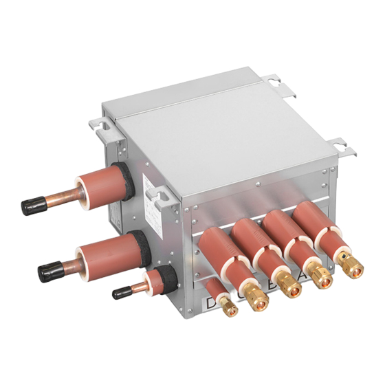
CH-Box
Models:
CH-AP04MSSX
CH-AP08MSSX
CH-AP12MSSX
CH-AP16MSSX
JCH-AP04MSSX
JCH-AP08MSSX
JCH-AP12MSSX
JCH-AP16MSSX
IMPORTANT:
READ AND UNDERSTAND
THIS MANUAL CAREFULLY
BEFORE INSTALLING
THIS CH-BOX.
KEEP THIS MANUAL FOR
FUTURE REFERENCE.
P5417025
FAN-2213 201711
Table of Contents

Related Manuals for Hitachi CH-Box

Summary of Contents for Hitachi CH-Box
- Page 1 Installation Manual Cooling / Heating Change-Over Box CH-Box Models: CH-AP04MSSX CH-AP08MSSX CH-AP12MSSX CH-AP16MSSX JCH-AP04MSSX JCH-AP08MSSX JCH-AP12MSSX JCH-AP16MSSX IMPORTANT: READ AND UNDERSTAND THIS MANUAL CAREFULLY BEFORE INSTALLING THIS CH-BOX. KEEP THIS MANUAL FOR FUTURE REFERENCE. P5417025 FAN-2213 201711...
- Page 3 Interchangeability between Current and New CH-Boxes ● New CH-Box is compatible for the new outdoor unit. Current CH-Box is compatible for the new outdoor unit with limitation. Refer to the Technical Manual for the outdoor unit for more details. Current outdoor unit is compatible with current CH unit only. (When the New CH-Box is connected to current VRF outdoor unit, the unit will not operate and the wired controller will display the alarm code “C4“.) 4: Available × Current CH Unit Current VRF (Heat Recovery) : Not Available × × New CH-Box New VRF (Heat Recovery) ● Current and new CH-Boxes can not be used in the same system together. ● Production of current CH unit shall be discontinued. However, it will be supplied for servicing and maintenance until further notice. Contact us if there are order request for the current CH unit. P5417025-rev.1...
- Page 4 IMPORTANT NOTICE ● The applicable outdoor unit may be different depending on the product series. Improper combination causes the unit to malfunction and an alarm will be triggered. Be sure to confirm with the product catalogue before installation. ● The manufacturer of the product pursues a policy of continuous improvement in the design and performance of products to meet regulatory requirements and industry standards. Therefore, the manufacturer reserves the right to revise specifications without notice. ● The manufacturer of the product cannot anticipate every possible circumstance that might involve a potential hazard. ● This heat pump air conditioner is designed for standard air conditioning applications only. Do not use this heat pump air conditioner for other purposes, such as drying clothes, refrigerating foods, or for any other cooling or heating process. ● Do not install the unit outdoors. Do not install the unit in the following places. It may cause a fire, deformation, corrosion or failure. * Places where there are high levels of oil mist (including machinery oil). * Places where there are high alkalinity levels (i.e., chlorine or bromine such as over hot tubs, etc.). * Places where flammable gases or liquids may be used or generated. * Places with a high concentration of salts, salty mists or sprays (such as over salt-water aquariums). * Places with an atmosphere of high nuisance dust. Places with organic solvent atmospheres, such as painting and cleaning locations. ● Do not install a unit in the place where condensate water can leak onto the unit or electrical device failures may occur. ● Pay attention to the following points when the unit is installed in a hospital or other facility where electromagnetic waves generate from medical equipment. * Do not install the unit in places where electromagnetic waves radiate to the electrical box, wired controller cable or wired controller. * Install the unit at least 3m (10 ft) away from electromagnetic waves or interferences such as a radio. ● The installer and system specialist shall secure against leakage according to local regulations or standards. This system has both high and low pressure refrigerant and, as such, comprises a pressurized system. Never loosen threaded joints while the system is under pressure and never open pressurized system parts. ● No part of this manual may be reproduced without written permission.
- Page 5 CHECKING PRODUCT RECEIVED ● Upon receiving this product, inspect it for any shipping damage. Inspect all electrical connections. Connections must be clean and tight at the terminals. Claims for damage either apparent or concealed, should be filed immediately with the shipping company. NOTE: Rough handling may dislocate internal components. ● Check the model number, electrical characteristics (power supply, voltage and frequency) and accessories to determine if they are correct with the ordering and shipping information, to ensure the correct unit has been shipped. To minimize the possibility of damage after inspection, the units should be installed and reassembled as soon as possible. The standard installation and general use of this unit is explained in this manual. Although common processes and procedures for installing units are presented in this manual, its use for installation of units otherwise indicated in this manual is not recommended. Please contact your local agent, as the occasion arises. Our liability shall not cover defects arising from the alteration performed by a customer without our consent in a written form. SAFETY SUMMARY Signal Words ● Signal words are used to identify levels of hazard seriousness. Definitions for identifying hazard levels are provided below with their respective signal words. DANGER : DANGER indicates a hazardous situation which, if not avoided, will result in death or serious injury. WARNING : WARNING indicates a hazardous situation which, if not avoided, could result in death or serious injury. CAUTION : CAUTION used with the safety alert symbol, indicates a hazardous situation which, if not avoided, could result in minor or moderate injury. NOTICE : NOTICE is used to address practices not related to personal injury. NOTE : NOTE is useful information for operation or maintenance.
- Page 6 SAFETY SUMMARY DANGER ● Do not perform installation work, refrigerant piping work, condensate pump, or condensate piping and electrical wiring connection without referring to the installation manual. If the instructions are not followed, it may result in a water leakage, electric shock or a fire. ● Use the specified non-flammable refrigerant (R410A) for the outdoor unit in the refrigerant cycle. Charge only R410A into the unit. Do not charge other materials into the unit such as hydrocarbon refrigerants (propane), oxygen, flammable gases (acetylene) or poisonous gases when installing, maintaining and moving the unit. These flammables are extremely dangerous and may cause an explosion, a fire, or injury. As originally manufactured, this unit contains refrigerant installed by the manufacturer of the product. The manufacturer of the product uses only refrigerants that have been approved for use in the unit’s intended country or market. Distributors similarly are only authorized to provide refrigerants that have been approved for use in the countries or markets they serve. The refrigerant used in this unit is identified on the unit’s faceplate and/or in the associated manuals. Any additions of refrigerant into this unit must comply with the country’s requirements with regard to refrigerant use and should be obtained from distributors. Use of unapproved refrigerant substitutes will void the warranties and can cause injury or death. ● Do not pour water into the indoor or outdoor unit. These units are equipped with electrical parts. Exposure to water may cause a serious electrical shock. ● Do not open the service cover or access panel for the indoor or outdoor units without turning OFF the main power supply. ● Do not touch or adjust safety devices inside the indoor unit or outdoor units. If these devices are touched or readjusted, it may cause a serious accident. ● Carefully check for escaping refrigerant gas. If there is significant leakage, it can cause difficulty in breathing. Turn OFF the main switch, and contact your service contractor if refrigerant leakage occurs. ● Make sure that the refrigerant leakage test is performed. Refrigerant (fluorocarbon) for this unit is incombustible, non-toxic and odorless. However if the refrigerant is leaked and comes in contact with fire, toxic gas will generate. Because fluorocarbon is heavier than air, the floor surface will be filled with it, which could cause suffocation. ● The installer and system specialist shall secure against refrigerant leakage according to local regulations or standards.
- Page 7 SAFETY SUMMARY WARNING ● Do not use any sprays such as insecticide, lacquer, hair spray or other flammable gases within approximately 1.3m (4 ft) from the system. ● If the circuit breaker or fuse is often activated, stop the system and contact your service contractor. ● Check that the ground wiring is securely connected. If the unit is not correctly grounded, it may cause electric shock. Do not connect the ground wiring to gas piping, condensate piping, lighting conductor or ground wiring for telephones. ● Before performing any brazing work, check to ensure that there is no flammable material around. When using refrigerant, be sure to wear leather gloves to prevent injury from cold. ● Insulate electrical wiring, condensate piping, and electrical components from threats posed by burrowing animals and temperature extremes. Failure to do so can, over time, deteriorate system performance. ● Secure the cables. External forces on the terminals could lead to a fire. ● Tighten the flare nut with a torque wrench in the specified manner. Do not apply excessive force to the flare nut when tightening. If you do, the flare nut can crack and refrigerant leakage may occur. ● When maintaining, relocating or disposing of the unit, dismantle the refrigerant piping after the compressor stops. ● Highly dangerous electrical voltages are used in this system. Carefully refer to the wiring diagram and these instructions when wiring. Improper connections and inadequate grounding can cause serious injury or death. ● Perform all electrical work in strict accordance with this installation and maintenance manual and all relevant regulatory standards. ● Use specified cables between units. ● Be sure to install circuit breakers (ground fault interrupter, isolating switch, molded case circuit breaker and so on), with the specified capacity. Ensure that the wiring terminals are tightened securely to recommended torque specifications. If a circuit breaker or fuse is frequently activated, shut down the system and contact your service contractor. ● Clamp electrical wires securely with a cable clamp after all wiring is connected to the terminal block.
- Page 8 CAUTION ● Do not step on the unit. ● Do not put any foreign material on the unit or inside the unit. ● Provide a strong and correct foundation so that: ● The outdoor unit is not on an incline. ● Abnormal sound does not occur. ● The outdoor unit will not fall down due to a strong wind or earthquake. NOTICE ● Be careful that moisture, dust, or variant refrigerant compounds not enter the refrigerant system during installation work. Foreign matter could damage internal components or cause blockages. ● Do not install the indoor unit, outdoor unit, wired controller and cable within approximately 3m (10 ft) of strong electromagnetic wave radiators such as medical equipment. ● After a long shutdown, apply power to the outdoor unit(s) at least 12 hours prior to operation of the system for preheating of the compressor oil. NOTE ● It is recommended that the room is ventilated every three to four hours. ● The heating capacity of the heat pump unit is decreased according to the outdoor air temperature. Therefore, it is recommended that auxiliary heating equipment be used in the field when the unit is installed in a low temperature region. P5417025-rev.1...
-
Page 9: Table Of Contents
1. Safety Summary .............................1 2. Structure .................................1 2.1 Dimensions .............................1 2.2 Refrigeration Cycle ..........................4 2.3 Necessary Tools and Instrument List for Installation ................5 3. Transportation and Handling ...........................6 3.1 Transportation ............................6 3.2 Handling of CH-Box ..........................6 3.3 Combination of CH-Box and Indoor Unit ....................6 4. CH-Box Installation ............................7 4.1 Factory-Supplied Accessories ........................7 4.2 Initial Check ............................8 4.3 Suspension Bolts ............................9 4.4 Installation ............................10 4.4.1 Marking of the Positions of the Suspension Bolts and Wiring Connections .......10... - Page 10 viii P5417025-rev.1...
-
Page 11: Safety Summary
Safety Summary ● Do not perform installation work, refrigerant Do not install the CH-Box and cable within approximately 3m (10 ft) from strong piping work or electrical wiring connection electromagnetic wave radiators such as without referring to our installation manual. - Page 12 Pipe Connection (I.D. 16.1) Electrical Box (I.D. 25.6) Ground Terminal (M5) (in Electrical Box) Power Supply Wiring Control Wiring Connection Connection ( 26) (3 x 26) Refrigerant Gas (Low Pressure) Pipe Connection (I.D. 28.75) Outdoor Unit Connecting Side Figure 2.2 Dimensions of CH-Box P5417025-rev.1...
- Page 13 Pipe Connection (I.D. 19.3) Electrical Box (I.D. 28.75) Ground Terminal (M5) (in Electrical Box) Control Wiring Connection Power Supply Wiring (4 x 26) Refrigerant Gas Connection ( 26) (Low Pressure) Pipe Connection (I.D. 32) Outdoor Unit Connecting Side Figure 2.3 Dimensions of CH-Box P5417025-rev.1...
-
Page 14: Refrigeration Cycle
Unit D Unit C Unit B Unit A To Indoor Unit Side Mark Part Name : Refrigerant Gas Pipe Connection : Refrigerant Liquid Pipe Connection Electronic Expansion Valve : Field Refrigerant Piping Strainer : Flare Connection : Brazing Connection : CH-Box Figure 2.4 Refrigeration Cycle Diagram P5417025-rev.1... -
Page 15: Necessary Tools And Instrument List For Installation
Indoor Unit Side : Refrigerant Gas Pipe Connection Mark Part Name : Refrigerant Liquid Pipe Connection Electronic Expansion Valve : Field Refrigerant Piping : Flare Connection Strainer : Brazing Connection : CH-Box Figure 2.5 Refrigeration Cycle Diagram 2.3 Necessary Tools and Instrument List for Installation Tool Tool Handsaw Wrench Phillips Screwdriver Charging Cylinder Vacuum Pump Manifold Gauge... -
Page 16: Transportation And Handling
Do not put any foreign material into the indoor unit and check to ensure that none exists in the CH-Box before the installation and test run. Do not put any material on the product. Otherwise, a fire or failure, or something similar may occur. -
Page 17: Box Installation
CH-Box Installation 4.1 Factory-Supplied Accessories Check to ensure that the following accessories are ● Do not install the CH-Box in a flammable packed with the CH-Box. environment to avoid fire or an explosion. NOTE If any of these accessories are not packed with the ● Check to ensure that the ceiling slab is strong unit, please contact your distributor. enough. ● Do not install the CH-Box outdoors. -
Page 18: Initial Check
4.2 Initial Check ● Install the CH-Box with a proper clearance ● Check to ensure that the ceiling is sufficiently around it for maintenance working space, as strong to sustain the CH-Box. If the ceiling is shown in Figure 4.1 below. weak, abnormal sound and vibration may occur. ● When the electronic expansion valve in the CH-Box is activated, a change in the typical Service Space Unit: mm refrigerant flow sounds may be heard or perceived from the CH-Box. Take the following Service Access Door 1 (*) Service Access Door 2 action to minimize the sound. 450) 450) (A) Install the CH-Box inside the ceiling. As for the ceiling material, select a material like a plasterboard at least 9mm (1 inch), which minimizes operation sound. (B) Do not install the CH-Box in a place near bedrooms or hospital rooms. Electrical Box ● When the operation is changed to cooling/... -
Page 19: Suspension Bolts
4.3 Suspension Bolts Step 1 (1) Select a final location and installation direction of the CH-Box. Pay careful attention to the space for the piping, wiring and maintenance. (2) Mount suspension bolts. (3) Contact a qualified contractor or carpenter for the ceiling treatment. View from above Unit: mm (inch) (13/16) (For Suspension Bolt) (7-13/16) Size Model CH-AP04MSSX (4-5/16) 340 (13-3/8) JCH-AP04MSSX CH-AP08MSSX 580 (22-13/16) JCH-AP08MSSX CH-AP12MSSX 820 (32-5/16) JCH-AP12MSSX CH-AP16MSSX Suspension Bracket... -
Page 20: Installation
4.4 Installation 4.4.1 Marking of the Positions of the Suspension (2) Hanging the CH-Box Bolts and Wiring Connections (a) Hang the CH-Box by putting hands on the bottom of the cabinet. (1) Mark the positions of the suspension bolts, (b) Insert the suspension bolt into the groove refrigerant piping connections and wiring part of the suspension bracket as shown connection. in Figure 4.5. Ensure that the washers (2) Installation dimensions are shown in are correctly affixed to the suspension Figure 2.1 and 2.2. bracket. (c) After the hanging work, the piping and 4.4.2 Mounting and Hanging the CH-Box wiring connection work is required inside the ceiling in the gap between the roof (1) Place nuts and washers onto the suspension and ceiling so it is not visible. Therefore, bolts before installing the CH-Box. determine the drawing direction of the NOTE: pipe after selecting the installation location Make sure to use washers for installing the of the CH-Box. Before doing the hanging suspension bolts to the suspension brackets. work, carry out the piping and wiring work Install the washer with the insulation side up to the connecting positions. -
Page 21: Refrigerant Piping Work
Refrigerant Piping Work ● Flaring Dimension Perform the flaring work as shown below. Use the specified non-flammable refrigerant mm (inch) (R410A) for the outdoor unit in the refrigerant Diameter cycle. Do not charge material other than -0.4(-0.02) (ɸd) R410A into the unit such as hydrocarbon R410A refrigerants (propane or something similar), 6.35 (1/4) 9.1 (0.36) oxygen, flammable gases (acetylene or etc.) or... - Page 22 ● Cautions for Piping Connection Work (a) Connect the indoor/outdoor connecting pipes. Secure the pipes and do not touch ● Do not apply excessive force to the flare other objects, such as ceilings for example. nut when tightening. Excessive force can (Otherwise, abnormal sound may be heard result in the flare nut cracking and refrigerant due to the vibration of the piping.) leakage may occur. Use the specified (b) Apply refrigerant oil slightly on the sheet tightening torque. surface of the pipe and flare nut before the ● For more details of the refrigerant piping flaring work. Then tighten the flare nut with...
- Page 23 5.2 Refrigerant Piping Work Provide the refrigerant pipe in the field. Make sure that the refrigerant pipe is connected to the same refrigerant cycle unit. (1) Position of Piping Connection Unit: mm (inch) (10-1/4) Refrigerant Liquid Pipe (7-13/16) Connection for Outdoor Unit I.D. φD (4-5/16) Refrigerant Gas (Low Pressure) Pipe Connection for Outdoor Unit Refrigerant Gas (High/Low Pressure) Electrical Box I.D. φC Pipe Connection for Outdoor Unit (1-5/8) I.D.
- Page 24 (2) Piping Work for CH-Box Refer to Technical Catalogue and Installation Manual of the outdoor unit for the piping diameter and the installation condition. (3) Selecting Piping Size ● Select the size for the high/low pressure gas pipe, (a) Outdoor Unit Connecting Side low pressure gas pipe and liquid pipe according High/Low Pressure to Table 5.1. The size depends on the indoor unit Gas Pipe (B) total capacity connected downstream of the (Field-Supplied) CH-Box. ● As for the multi-kit branch or header branch, refer Low Pressure Gas Pipe (A) to the Technical Catalog for the Outdoor Unit. (Field-Supplied) ● Perform the piping connection work for the CH-Box Liquid Pipe (C) as shown below. (Field-Supplied) Gas Pipe (D)
- Page 25 Details of changes to the piping size for connection to the CH-Box are shown below. CH-AP04MSSX JCH-AP04MSSX Unit: mm (inch) Piping Connection Required Field-Supplied Remarks Size for CH-Box Pipe Size OD25.4 ID19.05 Apply Field-Supplied Reducer f19.05 → (3/4) (3/4) (2 Size Down) ɸ22.2 OD25.4 ID22.2 → Apply Field-Supplied Reducer (7/8) (7/8) Low Pressure ɸ25.4 Gas Pipe (A) ɸ25.4 ɸ28.58 OD25.4 ID28.58 → Apply Field-Supplied Reducer (1-1/8) (1-1/8) ɸ12.7 OD22.2 ID12.7 Apply Field-Supplied Reducer →...
- Page 26 CH-AP12MSSX JCH-AP12MSSX Unit: mm (inch) Piping Connection Required Field-Supplied Remarks Size for CH-Box Pipe Size ɸ22.2 OD28.58 ID22.2 Apply Field-Supplied Reducer → (7/8) (1-1/8) (7/8) (2 Size Down) ɸ25.4 OD28.58 ID25.4 → Apply Field-Supplied Reducer (1-1/8) Low Pressure ɸ28.58 Gas Pipe (A) (1-1/8) ɸ28.58 (1-1/8) f34.93 OD28.58 ID34.93 → Apply Field-Supplied Reducer (1-3/8) (1-1/8) (1-3/8) f19.05 OD25.4 ID19.05...
- Page 27 (b) Indoor Unit Side Field Piping Size ● When a branch is located downstream of the CH-Box Connected Indoor Unit Gas Pipe (D) Liquid Pipe (E) Capacity: (Q) mm (inch) mm (inch) Q < 16.0 f15.88 (5/8) f9.52 (3/8) Q = 16.0 f19.05 (3/4) f9.52 (3/8) 1. Field flaring work is required. Refer to Section 5.1 for the flaring work. ● When a branch is not located downstream of the CH-Box Connected Indoor Unit Gas Pipe (D) Liquid Pipe (E) Capacity: (Q) Remarks mm (inch) mm (inch) Use accessory pipe (1) on gas pipe side Q ≤ 6.3 f12.7 (1/2) f6.35 (1/4)
- Page 28 1. In case of 8 and 10HP type indoor unit connection: Up to two 8 and 10HP type indoor units can be connected to the CH-Box within the “Maximum Total Capacity of All Connected Indoor Units”. Make sure to increase the pipe connection size by using the appropriate accessory pipe.
- Page 29 (c) Perform cold insulation work by insulating and taping the flare connection and reducer connection. Also insulate all the refrigerant pipes. Check that there are no gaps between Check there are no gaps between insulation materials. the CH-Box and the insulation. If the gaps are occurs, seal the gap with vinyl tape. Apply by making Insulation Material Insulation Material contact to the piping.
-
Page 30: Electrical Wiring
THE UNIT. FAILURE TO DISCONNECT POWER SUPPLY MAY RESULT IN ELECTRICAL SHOCK OR EVEN DEATH. ● Turn off the main power switch to the CH-Box, the indoor unit and the outdoor unit before electrical wiring work or a periodical check is performed. -
Page 31: Electrical Wiring Connection
6.2 Electrical Wiring Connection (1) Perform the electrical wiring work for the CH-Boxes. Select the wire size according to the table below. (2) Pay attention to the marks on the terminal block when connecting wires for CH-Box and I.U./O.U. Refer to “Example of Electrical Wiring” for the wiring connection on the next page. Table 6.1 Electrical Data and Recommended Wiring, Breaker Size Earth Leakage Main Switch Minimum Wire Thickness [mm Breaker (ELB) Earth Maximum Nominal Power Wire Current Nominal Nominal Power Source Transmitting Model Sensitive Fuse Supply Size Current Current Cable Size Cable Size Current [mA] ] EN60 335-1 MLFC EN60 335-1 MLFC CH-AP04MSSX JCH-AP04MSSX... - Page 32 Indoor Unit L Indoor Unit L Cooling Only Indoor Unit Communication Cable (Non-Polarity) When multiple indoor units are connected to the same branch of CH-Box, (DC5V) the operation mode (cooling/heating) for the indoor units will be the same. WC: Wired Controller NOTES: 1. Do not apply excessive voltage to the communication cable DC5V (non-polarity) between the outdoor...
-
Page 33: Electrical Wiring
(3) Connect the communication cable between the outdoor unit and CH-Box to TB2 of the CH-Box. Connect the communication cable between the CH-Box and indoor unit to TB3 and TB4 of the CH-Box. Ensure that the communication cable between the CH-Box and indoor unit is connected to the same letter as piping connection. (Tightening Torque: 1.0 to 1.3 N . m (0.7 to 1.0 ft . lbs)) Refer to “Example of Electrical Wiring” for the wiring connection. (4) Tightly clamp the wires using the cable clamp inside the electrical box. (5) Make sure the communication cables outside the electrical box does not touch sharp edges by securing with clamp (accessory (7)). (6) Attach the electrical box cover after completing the wiring work. Terminal Blocks for Communication between CH-Box and Indoor Unit Ground Terminal Terminal Block PCN1 PCN2 PCN1 PCN2 PCN1 PCN2 for Power Supply PCB1... -
Page 34: Setting Of Dip Switches
6.4 Setting of DIP Switches DSWs on the PCB1 are set before shipping as shown below and no setting is required. Connection Ports for Indoor Unit Table 6.2 Cross reference table of DIP switch settings and connection ports for indoor unit. CH-AP16MSSX CH-AP12MSSX Models JCH-AP16MSSX CH-AP08MSSX PCB1 PCB4 JCH-AP12MSSX CH-AP04MSSX JCH-AP08MSSX DSW1 DSW1 JCH-AP04MSSX DSW2 DSW2 DSW3 DSW3 Connection ports for indoor unit PCB1 PCB2... -
Page 35: Test Run
Test Run NOTICE Refrigerant piping and connecting wires should be connected to the same refrigerant cycle system. If they are connected to the dissimilar refrigerant cycle systems, a malfunction may occur. ● Special Attention Regarding Refrigerant Gas Leakage The refrigerant R410A is non-toxic and inflammable in its original state. However, in consideration of a state where the refrigerant leaks into the room, measures against refrigerant leaks must be taken in small rooms where the tolerable level could be exceeded. -
Page 36: Safety And Control Device Setting
Table 7.1 Alarm Code Code Category Content of Abnormality Leading Cause Incorrect Wiring, Loose Terminals, Disconnected Abnormal Communication between Communication Communication Cable, Blowout of Fuse, Indoor Unit Power Indoor Units and Outdoor Units 2 or More CH-Boxes are Connected between Incorrect CH-Box Connection Outdoor Unit and Indoor Unit 9 or More Indoor Units Connected to Single Branch Type CH-Box Incorrect Indoor Unit Connection Number 7 or More Indoor Units Connected per a Branch of Multiple Branch Type CH-Box CH-Box Incorrect Indoor Unit Refrigerant Number Indoor Units of Different Refrigerant Cycle Number are Setting Connected to CH-Box Incorrect Connection between Ch-Box and This Outdoor Unit is not compatible with this CH-Box. Outdoor Units Indoor Unit is connected to a port that is set to not used for Incorrect Connection Port Setting Multiple Branch Type CH-Box. Safety and Control Device Setting CH-Box CH-AP04MSSX, CH-AP08MSSX, CH-AP12MSSX, CH-AP16MSSX Model JCH-AP04MSSX, JCH-AP08MSSX, JCH-AP12MSSX, JCH-AP16MSSX For Control Circuit Fuse P5417025-rev.1... - Page 37 P5417025-rev.1...
- Page 38 P5417025-rev.1...
- Page 39 P5417025-rev.1...
- Page 40 © 2017 Johnson Controls-Hitachi Air Conditioning Technology (Hong Kong) Ltd. P5417025-rev.1, 2017 Printed in China...