
Related Manuals for Mitsubishi Electric LGH-15RX5 -E


Summary of Contents for Mitsubishi Electric LGH-15RX5 -E
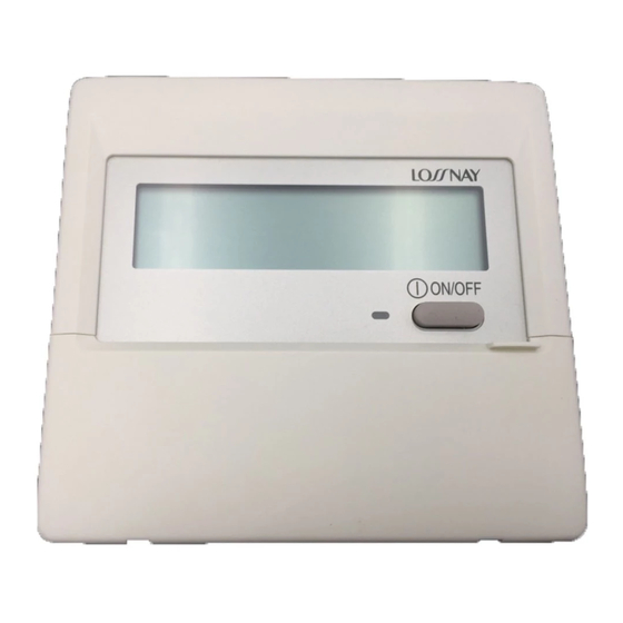
- Page 1 Lossnay Remote Controller...
- Page 3 ● Lossnay M-NET Remote Controller ( PZ-52SF-E ) Use with Mitsubishi Electric Air conditioner Network system ( MELANS ) (Refer to page C-92). Because the remote controller is power-supplied using the M-NET transmission line, it cannot be linked with Mr. Slim and other such systems that do not use M-NET.
- Page 4 3. Terminology ● Interlocked Lossnay A Lossnay linked to City Multi or Mr. Slim indoor units that has been set to interlocked group setting to receive signals and operate via indoor unit’s remote controller. (Remote controller to indoor unit to Lossnay.) ●...
- Page 5 4. System Features and Examples Features Classification Item Notes/Cautions Control • Multiple unit operation Maximum 15 units with PZ-60DR-E & PZ-41SLB-E; 16 units with PZ-52SF-E or other M-NET controllers. • Remote controller operation Last condition priority before turning off the unit. •...
- Page 6 System Examples One Lossnay with one remote controller Multiple Lossnay units with one remote controller Two remote controller system with one Lossnay Lossnay Non-polar Non-polar Two wires Lossnay Non-polar (Main) Two wires Lossnay Two wires Power supply Lossnay Power supply Power supply Remote (Sub)
- Page 7 Two remote controller system with multiple Lossnay units Use Lossnay remote controller PZ-60DR-E or PZ-41SLB-E . (Do not use PZ-52SF-E). Lossnay transmission connection terminal Power supply Remote controller input terminal Power supply PZ-60DR-E Remote controller PZ-60DR-E or PZ-41SLB-E Transmission wires Setting ●...
- Page 8 System Selection Interlocked with City Multi Incase of PZ-60DR-E ( Refer to page C-14 ) ● ● Lossnay operation when indoor unit is stopped Lossnay conditioner conditioner ● ● Lossnay stopping when indoor unit is operating Switching Lossnay fan speed MA remote M-NET transmission cable When interlocked with indoor unit for compatibility with both R22, R407C and R410A...
- Page 9 Centralized Controller System Centralized controller AG-150A Outdoor unit Interlocked with City Multi indoor units Indoor unit LOSSNAY RX Indoor unit Power supply unit (PAC-SC51KUA) M-NET remote LOSSNAY remote M-NET remote controller controller controller PZ-60DR-E Interlocked with Mr. Slim indoor units LOSSNAY RX Mr.Slim Mr.Slim...
- Page 10 Reference: Remote controller for the Lossnay and indoor unit Refer to the technical documentation related to the Remote controller for the indoor unit. Remote controllers for Lossnay unit Lossnay remote controller Lossnay remote controller Lossnay M-NET remote controller (PZ-60DR-E) (PZ-41SLB-E) (PZ-52SF-E) *non M-NET protocol *non M-NET protocol...
- Page 11 Basic System 4.4.1 System Summary Design Example 1 Basic system Design Example 2 Lossnay control of multiple units ● Up to 15 Lossnay units can be controlled at one time with one Lossnay Non-polar remote controller switch. Lossnay Two wires Non-polar (Main) Two wires...
- Page 12 4.4.3 Operation with two Remote controllers Characteristics Remote controller Note • Lossnay can be operated from two remote locations. • Use only up to two remote controllers • Lossnay conditions can be checked from two remote Lossnay remote controller (Operation will not go normally if three locations.
- Page 13 Interlocking with Mr. Slim 4.5.1 Interlocked Mr. Slim and Lossnay System Features ● It is possible to Interlock Mr. Slim indoor units with Lossnay operation. System Example Mr. Slim outdoor unit Mr.Slim indoor unit Lossnay unit LGH-RX type Slim-Lossnay connection cable ( Enclosed accessory with Lossnay unit) Remote controller Lossnay Function Table ( Interlocked settings )
- Page 14 4.6.1 Independent Lossnay System with Lossnay M-NET Remote Controller and MELANS Features ● The Mitsubishi Electric air-conditioner network system ( MELANS ) can operate and monitor each group of Lossnay units and City Multi indoor units. ● Can also use the Lossnay M-NET remote controller to operate.
- Page 15 System Examples: 2 (Lossnay M-NET Remote Controller PZ-52SF-E) The following groups can be configured. ● Further information please refer LGH-RX Technical Manual. Centralized controller ( 000 ) ( ) address Lossnay Lossnay Lossnay Lossnay Lossnay Lossnay Lossnay Lossnay Power (001) (002) (003) (004)
- Page 16 Lossnay Function Table ( Group Setting ) Item Details Five units Number of Lossnay remote controllers and/or MELANS ( Number of Lossnay remote controller(PZ-60DR-E or PZ- remote controllers that can be connected to one Lossnay unit 52SF-E) is two units max. ) Operation of two remote controllers in one group Possible Switching fan speed...
- Page 17 4.6.2 City Multi and Lossnay Interlocked System Characteristics ● It is possible to interlock City Multi indoor units with Lossnay operation. ● Independent Lossnay operation can also be performed using MA remote controller or ME remote controller. ● Non M-NET Lossnay remote controller PZ-60DR-E can be used with any Lossnay units in this application. System Examples The following groups can be configured.
- Page 18 Lossnay Function Table (Interlocked Settings) Item Details Number of indoor units that can be set to interlocked opera- 16 units per group tion with one Lossnay unit in each group Number of Lossnay units that can be set to interlocked oper- one unit ation with one indoor unit Independent Lossnay start/stop operation...
- Page 19 4.6.3 MA Remote Controller/ME Remote Controller in Combination with Lossnay Non-M-NET Remote Controller (PZ-60DR-E) System Combining MA, ME and Lossnay Non M-NET remote controllers is permitted. ● In case of combination with Lossnay M-NET remote controller (PZ-52SF-E) please refer LGH-RX Technical Manual.
- Page 20 System Examples: 2 A sophisticated system including City Multi can also be configured. Centralized controller ( 000 ) ( ) address M-MET Lossnay Lossnay Lossnay Lossnay Lossnay Lossnay Lossnay Lossnay(008) Power (001) (002) (003) (004) (005) (006) (007) supply unit Lossnay remote Lossnay remote Lossnay remote...
- Page 21 ® 4.6.4 When Using the LONWORKS Compatible Adaptor (LMAP02-E) ® to Connect to LONWORKS ® ® By using the LON adaptor (model name: LMAP02-E) to connect to LONWORKS , it is possible to control and observe Lossnay operation on a building management system. ®...
- Page 22 5. Examples of Applications Using Various Input and Output Terminals Various applications are possible by using the input/output termi- nals and connectors as shown below. Input/Output Specifications Terminal Specification Page External control input TM2 is the input terminal block for start/stop the Lossnay unit using external C-26/C-27 equipment, such as a Mr.
- Page 23 External Control Operating Mode Selection There are four modes when operating using signals from external equipment. 1. ON/OFF interlock ( the chosen function from either external signal or remote control switch has priority ) 2. ON interlock 3. OFF interlock 4.
-
Page 24
Delayed Interlocked Operation It is possible to delay operation of the Lossnay if an external device is operating. (Energy saving capability.)
(Refer to page C-91, Remote controller to be set) ● Choose from 10, 20, 30, 40, 50, and 60 minute delayed Lossnay operation. ●... - Page 25 Multiple Lossnay Units Interlocked with One Indoor Unit (M-NET only) [ Example: System 1 ] Set the Main/Sub switch of the Lossnay connected to the M-NET transmission cable to “Main,” set the other Lossnay units to “Sub,” and connect 1 and 2 of the Lossnay remote controller (PZ-60DR-E or PZ-41SLB-E) transmission cable terminal (TM4) to the corresponding terminal on the next unit.
- Page 26 Operation monitor output (Refer to page C-70) [ Example System ] M-NET transmission cable Lossnay Indoor unit Electrically operated damper/ Booster fan etc. MA remote Operation monitor output (TM4 controller Malfunction monitor output (Refer to page C-69) [ Example System ] M-NET transmission cable Lossnay Indoor unit...
- Page 27 3. When the external device has an uncharged a-contact signal.(Refer to page C-68) Connect the operating signal (wire) from the external device Lossnay External controller input (TM2) via the remote output to 1 and 3 on the external control 0.5 mm to 1 mm sheathed PVC cable input terminal block (TM2).
- Page 28 7. ON/OFF power operation without using the remote controller. Connect as shown in the wiring diagram to the left. Switch When the Switch ON, the LOSSNAY unit will begin to oper- ate. Power source for LOSSNAY *LOSSNAY FAN speed can be selected (High/Low) through Lossnay DIP switch 2-4 and 2-5.
- Page 29 1 When using PZ-60DR-E or PZ-41SLB-E to connect multiple Lossnay units ● Connect the sensor to the Lossnay set to “Main”. ● It is not necessary to connect to any Lossnay with the “Sub” setting. ● Connect any sensor, etc., with the external change input to the Lossnay unit set to “Main”. ●...
- Page 30 ● One shielded wire is connected to TB5 on the PCB on terminal.Address setting is required. (Refer to function setting section.) M-NET transmission cable: Connect any of the City Multi indoor unit, or Mitsubishi Electric Air-Conditioner Network System (MELANS) - to the Lossnay.
- Page 31 6. Precautions When Designing M-NET Systems M-NET Transmission Cable Power Supply On an M-NET system, the remote controller or central controller operate on power from the transmission cable. Accordingly, there is need to provide power to the transmission cable. Two systems are available for supplying power: the central system is supplied by a power supply unit; the indoor unit system is supplied by an outdoor unit.
- Page 32 Power consumption of each central controller Number of conversion as Lossnay remote controller Model G-50A Two units Centralized controller GB-50A Twelve units System remote controller PAC-SF44SRA Two units Four units ON/OFF remote controller PAC-YT40ANRA Schedule timer PAC-YT34STA Two units Centralized controller AG-150A Two units Wiring Example...
- Page 33 Power Supply to the Indoor Unit Transmission Cable The number of ME and Lossnay M-NET remote controllers that can be connected to one outdoor unit will depend on the type of outdoor unit. See below for the general guidelines when connecting multiple indoor units of air conditioner and Lossnay units to an outdoor unit.
- Page 34 7. M-NET Cable Installation Precautions When Installing Wiring 1. When routing the transmission cable outside of all units, position it 5 cm or more away cable for the power supply so that it will not pick up electrical noise. ( Never use multi- core cable or place the transmission cable in the same conduit as the power supply cable.
- Page 35 Electrical Wiring Types of control cables 1. Wiring the M-NET transmission cables • Types of transmission cables Two-core shielded cable (CVVS, CPEVS). • Diameter 1.25 mm to 2.00 mm • Maximum length from an end to the other end Less than 200m 2.
- Page 36 Control Cable Length ● Maximum power supply cable length ( L1 + L2, L1 + L3, L1 + L4 + L5 ) : the longest length of the cable from the power supply unit or the indoor unit of air conditioner to the farthest terminal cannot be more than 200 m. ●...
- Page 37 8. M-NET System Designs Address Definitions An address is a unique number used to identify each indoor unit of air conditioner and controller. Unit Address setting Example Note Use the smallest address within the same group of indoor units. Make the address of the indoor units Indoor unit of air conditioner connected to the sub BC controller larger than the 01 to 50...
- Page 38 System configuration example ( ) address M-NET Centralized controller AG-150A ( 051 ) Outdoor unit 24 VDC ( 003 ) ( 101 ) ( 001 ) ( 002 ) ( 103 ) Power ( 004 ) supply Indoor unit Indoor unit Indoor unit unit Lossnay...
- Page 39 Precautions When Setting the Groups ( when not interlocked with City Multi indoor units ) Precautions The maximum number of Lossnay units in one group is 16. ( Refer to page C-16. ) When two remote controllers are used within the same group, set one remote controller as the main ( address 101 to 150 ) and the other as the sub ( address 151 to 200 ) .
- Page 40 9. Automatic Ventilation Switching Effect of Automatic Ventilation Mode The automatic damper mode provides the correct ventilation for the room conditions. It eliminates the need for troublesome switch operations when setting the Lossnay ventilator to “By-pass” ventilation. The following shows the effect “By-pass” ventila- tion will have under various conditions.
- Page 41 Remote controllers System Ventilation mode System controllers Stand-alone/multi- Lossnay remote controller The “Function selector” button of the remote controller ple Lossnay and PZ-60DR-E permits ventilation mode switching for automatic, Loss- Lossnay remote nay, and bypass ventilation. Bypass ventilation is set at controller: PZ- the time of night purge operation, and ventilation mode 60DR-E...
- Page 42 a. Systems interlocked with Mr. Slim and City Multi indoor units The map will differ depending on the operation mode that has been set with the A-control remote controller or the K-control remote controller for Mr. Slim, or the MA remote controller or the ME remote controller for City Multi indoor units.
- Page 43 Pattern 2. Outdoor cooling priority mode When the outdoor temperature is lower than the indoor temperature, this mode actively takes in the outdoor air for cooling. When PZ-60DR-E is used, operation will be at the setting of automatic ventilation adjustment pattern “2” of the remote con- troller function selection.
- Page 44 10. Troubleshooting ■ n Work precautions • When removing or touching a transformer, printed circuit board or other parts, make sure to turn off the power supply isolator. • When removing the circuit board, always hold it at both ends and remove carefully so as not to apply force to the surface mounted parts.
- Page 45 10.2 Checklist 10.2.1 Troubleshooting 1 : The system will not start properly Initialization checklist from installation to operation (Table 1-1) After checking the system, verify the checkpoints listed below. Power supply (Table 1-1-1) Checkpoint Action Is the main power supply on? Turn on the main power supply.
- Page 46 Signal cables from external devices (Table 1-1-3) Check the following checkpoints when connecting with level signal/pulse signal output devices, and Mr. Slim units. Checkpoint Action Do the transmission cables meet regulations? (Type, diameter) Use specified cables. Is the signal cable wired at least 5 cm away from the power supply cable? Wire the signal cable at least 5 cm away from the power supply cable.
- Page 47 Signal cables to external devices (Table 1-1-4) Check the following checkpoints when outputting the operation monitor, air supply fan operation monitor, mal- function monitor, bypass operation monitor, and operation monitor with delay function. Checkpoint Action Do the signal cables meet regulations? (Type, diameter) Use specified cables.
- Page 48 System checklist (Table 1-2) When using PZ-60DR-E, PZ-41SLB-E, or interlocking with external devices (Table 1-2-1) Error Cause Action « Power is not supplied to the Lossnay, or power « Check the power supply to the • Remote controller display does not that does not follow specifications is used.
- Page 49 Error Cause Action « The interlock mode is set to “ON Interlocked” or « Check the Interlock mode setting Interlock operation with external device “OFF Interlocked” with the remote controller (PZ- with the remote controller (PZ- does not occur. 60DR-E). 60DR-E).
- Page 50 Error Cause Action « Power is not supplied to Lossnay, or power that « Check the power supply to Lossnay Cannot perform group settings for the Lossnay does not follow specifications is used. and perform the registration again. using MELANS, ME «...
- Page 51 Error Cause Action « The specified power is not supplied to Lossnay. « Check the power to Lossnay. The remote controller PZ-52SF-E continues to « Group setting of the PZ-52SF-E address has « Check the address registration blink “HO” when the not been performed with MELANS.
- Page 52 10.2.2 Troubleshooting 2 ● l An error code displays on the remote controller. ● l The LED on the Lossnay circuit board is blinking or lit up. An error code displayed on the remote controller (PZ-60DR-E, PZ-41SLB-E, PZ-52SF-E) or the M-NET con- troller, and blinking or illumination of LED1 (green) or LED2 (red) on the circuit board shows the type of error.
- Page 53 LED1 LED2 Error code Error Cause Action (green) (red) « Damper board operation is not cor- « Remove the rod, and check whether the LC 3602 — Damper blinks related rect. damper board can be moved manually. SLC 3602 error «...
- Page 54 Checklist of error codes displayed on PZ-60DR-E (when using M-NET), PZ-52SF-E or M-NET controllers, and LED displays(Table2-2) LED1 LED2 Error code Error Cause Action (green) (red) « There is another unit with the same « Check the addresses of devices in 6600 —...
- Page 55 LED1 LED2 Error code Error Cause Action (green) (red) « When using multiple Lossnay units, the « Turn off the main power supply and set the 6801 — PZ-60DR-E blinks communi- Main/Sub setting has not been made Main/Sub selection switch (SW1) (first unit to cation error for the second unit and following units.
- Page 56 10.2.3 Troubleshooting 3 : The remote controller operation is disabled or irregular Checklist for PZ-60DR-E or PZ-41SLB-E (Table 3-1) Error Cause Action « Transmission cable is connected to the wrong « Check the transmission cable con- Nothing displays on the nection.
- Page 57 Error Cause Action « The bypass ventilation switching external input « Check the bypass ventilation The ventilation mode cannot be switched with (CN16) is set to ON. switching input (CN16). the remote controller. (Refer to page C-70) « When using PZ-60DR-E, “RECOVERY SET- «...
- Page 58 Error Cause Action « It is less than 10 minutes since the power was « After supplying power to the sys- Continues to display “HO” and does not start. supplied to the system. tem, “HO” blinks for a maximum of about 10 minutes. (This is not an error.) «...
- Page 59 10.2.4 Troubleshooting 4 : The Lossnay operation is disabled or irregular Lossnay checklist (Table 4) Error Cause Action « Connectors for the fan or connectors for the « Check the lead wire connectors The fan does not operate. Lossnay circuit board section are not correctly and the Lossnay circuit board The fan does not operate connected.
- Page 60 Error Cause Action « When using PZ-60DR-E, “RECOVERY SET- « Check the power supply Lossnay operates when the main power is turned TING” is set to “on” or “AUTo” with the function ON/OFF/AUTO setting with the selection of the remote controller. PZ-60DR-E function selection.
- Page 61 Error Cause Action « The outdoor air temperature is 8°C or lower. « Check the outdoor air temperature. The damper board does not operate. « The bypass ventilation switching external input « Check the bypass ventilation (CN16) is set to ON. switching input (CN16).
- Page 62 It is normal in the following cases. Error Cause Immediately after turning on LED1 blinks at 1 second intervals during starting operation (maximum of 45 sec- the main power, LED1 (green) onds). on the Lossnay circuit board blinks. LED1 (green) on the Lossnay LED1 will be lit during the delay operation when the delay operation setting is circuit board is lit.
- Page 63 Error Cause When PZ-60DR-E is used, the Timer operation does not work in the following circumstances: timer operation does not work. • When the timer function is set to OFF. • During the day of the week and time setting / During function selection / During timer setting •...
- Page 64 11. Installation method 11.1 Electrical installation With this product, the wiring installation method will vary according to the design of the system. Perform electrical installation to meet local electrical regulations. * Always use double insulated PVC cable for the transmission cables. * Wiring work must be performed by qualified professionals.
- Page 65 11.1.3 Wire connection diagram ----- Models LGH-150 and 200 RX * Connect the wires shown as thick lines. * Be sure to connect the ground wire. * A power supply isolator must be installed when wiring power supply to unit. * Always use a single pole isolator for the main switch power connection.
- Page 66 When switching By-pass externally. When using the remote/local switching and the ON/OFF input (level signal) 10. When connecting to the City Multi, Lossnay remote controller (PZ-52SF-E) or Mitsubishi Electric Air-Conditioner Network System (MELANS). CAUTION: •...
- Page 67 1. When connecting with remote controller (PZ-60DR-E, PZ-41SLB-E) * When controlling Lossnay units with the central control, con- nect wires according to 10 (Refer to C-71). Lossnay Securely connect the transmission cable (PVC insulated PVC p to two remote controllers jacketed and either between ø...
- Page 68 (1)Connect the interlocking cable connector side to CN2L on Lossnay Slim-Lossnay connection cable External controller input (TM2) the circuit board for the indoor Mr. Slim unit, then connect the (Enclosed accessory) lead wire side to the 1 and 2 of the input terminal block (TM2) for the Lossnay external controller input.
- Page 69 3.When interlocking with a pulse output device (1) Move the pulse input switch [SW2-2] to the ON position.(Refer to function settings 1 (Refer to C-73) 3 4 5 6 7 8 9 10 “Settings for pulse input”.) (2) Connect the pulse output device (i.e., building management system) to the external control input terminal block [TM2].
- Page 70 6. When connect to an Electrically operated damper, or take Operation monitor output Connect the power supply cable from the Electrically operated Power Supply damper to 9 and 0 of the monitor output terminal block (TM4) Monitor output terminal (TM4) with reference to the wire connection diagram.
- Page 71 Max wiring length 10 m 10.When connecting to the City Multi, Lossnay remote controller (PZ-52SF-E) or Mitsubishi Electric Air-Conditioner Network System (MELANS) * If centralized control is performed according the wire connection shown in this section, the remote controller (PZ-41SLB-E) cannot be used.
- Page 72 11.4 Function settings Address setting is requiered when connecting to City Multi, Lossnay remote controller (PZ-52SF-E) and MELANS. 11.4.1 Setting the address Use the following procedure when setting the address for dedi- LGH-50 and 100RX types cated Lossnay. (The method in determining the addresses will depend on the existing system.
- Page 73 1. Settings for pulse input Set as shown when connecting the pulse signal equipment from a building maintenance system to an external input. Mode No pulse input (factory setting) Pulse input 2. Switching to power supply/exhaust when operation starts This sets the fan to run forcibly for 30 minutes when operation starts to ventilate the indoor area. After 30 minutes, the sys- tem switches to enable fan speed adjustment from the remote controller.
- Page 74 5. By-pass automatic ventilation priority setting Two thermistors in the Lossnay unit detect the indoor (RA) and outdoor (OA) air temperatures and automatically select the “Lossnay ventilation” or “By-pass ventilation”. With this mode, however, priority is given to the “By-pass ventilation”. This setting reflects to the night purge operation condition.
- Page 75 10.Exhaust fan stop during defrosting, exhaust fan Low speed operation at outdoor air lower than -15°C Sets the operation of the exhaust fan (when the air supply fan is stopped) during defrosting of the air conditioner when Mr. Slim or City Multi indoor unit is connected to a duct. When the outdoor air is lower than -15°C, stop the operation of exhaust fan.
- Page 76 14.Settings for interlock mode These settings indicate how Lossnay should operate when external devices are started or stopped. (If the PZ-41SLB-E is used, set it at the remote control.) Mode Operation The Lossnay will start and stop according to the operation On/Off interlock of the external devices.
- Page 77 11.5.3 Complete system trial operation ■ Interlock system containing an indoor unit and/or external device • Use the remote controller for the indoor unit or the operating switches for the external device and confirm that the indoor unit and Lossnay are interlocked. •...
- Page 78 12. Lossnay Remote Controller (PZ-60DR-E) 12.1 Parts Names Display Section For purposes of this Day-of-Week explanation, all parts of the display are shown as lit. Shows the current day of the week. During actual operation, only the relevant items will be lit. TIME/TIMER Display “Locked”...
- Page 79 12.2 Setting the Day of the 12.3 Using the Remote Controller Week and Time Typical System Setup ■ Use this screen to change the current day of the week and time setting. In either case, up to two remote controllers can be used. Two remote controller operation Note: •...
- Page 80 Pressing Function Selector button Ventilation mode Display Display will change AUTO automatically depending on environmental circumstances. HEAT EX. * If either “HEAT EX.” or “BY-PASS” is selected and blink alternately at an interval of five seconds in the dot display, it is recommended to select “AUTO”.
-
Page 81
button 4 to 9. After making the appropriate settings at Steps 5, 6, 7. and 8, press the
lock in the values. Timer Setting * “TIMER SET” indicator flashes three times. Note: Action (ON or OFF) Your new entries will be cancelled if you press the BACK button 2 before pressing the button 4. - Page 82 Examples Night Purge mode is active; no operation If ON and OFF times have both been set at the simple timer, operation and display are as indicated below. 1:00 A.M. Example 1: The outdoor temperature (OA) setting can be selected either 17°C or 28°C by using Start the timer, with ON time set sooner than OFF time Dip-Switch (SW2-7) in the Lossnay control ON Setting: 3 hours...
- Page 83 • If you press a locked button, the “Locked” indication (at ) will blink on the When the operation of Lossnay unit is started by external device,“INTERLOCKED” display. is displayed on the remote controller display . Timer mode is cancelled when the Lossnay unit is started by external device while the operation start timer has been set, or when the Lossnay unit is stopped by external device while the operation stop timer has been set.
- Page 84 12.6 How to Install 1. Choose a place in which to install the remote controller (switch box). Extra space External size Be sure to observe the following steps: around remote of remote controller (1) When installing on either the switch box or the wall, allow extra space around the remote controller as controller shown in the figure at the right.
- Page 85 6. Wiring hole for installing directly on the wall (or open wiring) • Cut of f the shaded area from the upper cover using a knife, nippers, etc. • Take out the remote control cord connected to the terminal block via this portion. 7.
- Page 86 12.8 Function Selection Function selection of remote controller The setting of the following remote controller functions can be changed using the remote controller function selection mode. Change the setting when needed. Item 1 Item 2 Item 3 (Setting content) [1] Change Language Language setting to display Display in multiple languages is possible.
- Page 87 Dot display The language that is selected in CHANGE LANGUAGE mode appears on this display. (calc) English is set in this manual. Temperature display ON/OFF button Fan speed Adjustment button Button CLEAR button “Extra Low” fan speed button OPERATION button OPERATION buttons Ahead Back...
- Page 88 • If the remote controller Function Selection mode is entered during timer operation, the timer operation will be cancelled. Set timer operation after completing the remote controller Function Selection mode. • When using two remote controllers, if one remote controller is set to remote controller Function Selection mode, “ ”...
- Page 89 [1] Change Language [4] Display change The language that appears on the dot display can be selected. (1) Filter cleaning setting (SW5-5) • Press the [ MENU] button to change the language. Set to OFF to disable Filter maintenance display. Japanese ( ) (ja), English (en), German (de), Spanish (es), To switch the setting, press the [...
- Page 90 The calculated value for standard exchange efficiency is displayed, so the indicated Dot display Display Function Check temperature may differ from the actual SA temperature. If you want to display a value Corresponds to opertation mode output that is closer to the actual temperature, perform exchange efficiency correction. exhaust fan (Factory setting) •...
- Page 91 13. Lossnay Remote Controller (PZ-41SLB-E) Operation [2CONTROLLERS] Display [INTERLOCKED] Display Displayed when two Lossnay remote Displayed when the Lossnay operates via controllers operate the Lossnay unit(s). interlocked indoor unit or external signal. Note that the most recent operation request from either controller is given priority. Fan Speed Display Displays the selected fan speed.
- Page 92 14. Lossnay M-NET Remote Controller (PZ-52SF-E) Operation [CENTRAL] Display [INTERLOCKED] Display Displayed when remote operation is Displayed when the Lossnay unit starts prohibited by a centralized control unit, etc. operation via interlocked indoor unit or external signal. Ventilation Modes [Fan speed] Display Indicates the ventilation mode.
- Page 93 15. Appendix 15.1 Centralized Controller (AG-150A) * For details on other function settings, refer to the manual for the AG-150A. C-93...
- Page 94 C-94...
- Page 95 C-95...
- Page 96 C-96...
- Page 97 C-97...
- Page 98 C-98...
- Page 99 C-99...
- Page 100 15.2 Remote Controllers for Mr. Slim indoor units MA remote controller (PAR-21MAA) Without Lossnay interlock and indicators. [Ventilation] Display Displayed during ventilation (Lossnay) operation. TIME SUN MON TUE WED THU FRI SAT TIMER AFTER AFTER ERROR CODE FUNCTION FILTER WEEKLY SIMPLE ONLY1Hr.
- Page 101 15.2.2 Function Selection Perform only when change is necessary with Mr. Slim indoor unit. (Cannot be perf med with CITY MULTI control system.) Set the functions of each indoor unit from the remote controller as required (See Table 1 for a list of functions). Table 1.
- Page 102 [Procedure] (Set only when change is necessary.) Check the settings of each mode. When the mode settings were changed by function selection, the functions of that mode also change. Check the settings as described in steps 2 to 7 and change the setting based on the entries in the Table 1 function selection. For factory settings, see the indoor unit installation manual. Set the remote controller to OFF.
- Page 103 15.3 ME Remote Controller (PAR-F27MEA) CENTRALLY CONTROLLED 1Hr. DAILY ON OFF AUTO OFF CLOCK REMAINDER FILTER CHECK MODE TEST RUN STAND BY LIMIT TEMP. ERROR CODE NOT AVAILABLE DEFROST TEMP. ON/OFF CLOCK→ON→OFF FILTER CHECK TEST TIMER SET PAR-F27MEA 15.3.1 Operating Lossnay with ME remote Controller (When Interlocked with City Multi Indoor Unit) Operation method is same as A-control remote controller.
- Page 104 4 To register the interlocked operation of the Lossnay unit and the indoor unit. Use the [TEST RUN] buttons (shown as D) to register the interlock between the Lossnay indicated in “OA UNIT • ADDRESS NO.” and the indoor unit indicated in “INDOOR UNIT ADDRESS NO.” •...
- Page 105 9 Press the “Timer/continuous” button (shown as E) again. The display will now alternate between the registered unit and the address of the next registered unit. (Display is the same as in step 8.) Address of another INDOOR UNIT ADDRESS NO. OA UNIT ADDRESS NO.
-
Page 106
Y08-004 Jan.2009
...