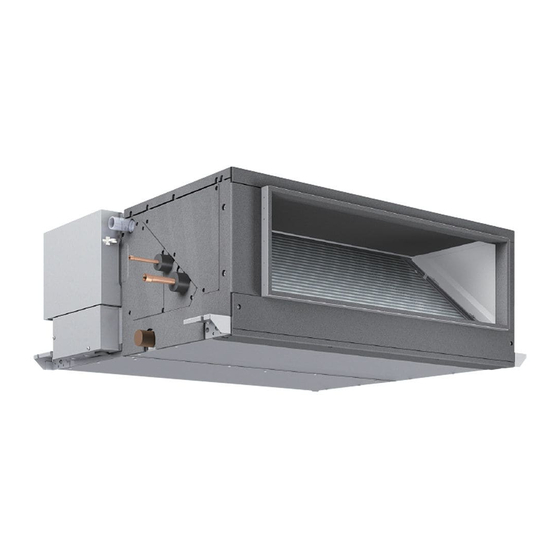
Mitsubishi Electric CITY MULTI PEFY Series Technical And Service Manual
Ceiling concealed (fresh air intake type)
Hide thumbs
Also See for CITY MULTI PEFY Series:
- Technical & service manual (35 pages) ,
- Technical & service manual (28 pages) ,
- Technical & service manual (32 pages)
Table of Contents

Related Manuals for Mitsubishi Electric CITY MULTI PEFY Series


Summary of Contents for Mitsubishi Electric CITY MULTI PEFY Series
- Page 2 Indicates a parts that requires grounding. the ones that are recommended by Mitsubishi Electric may result in smoke, fire, or explosion. Indicates that caution must be taken with rotating parts. (This Consult your dealer for proper disposal method.
- Page 3 Do not use a charging cylinder. - If a charging cylinder is used, the composition of the refrigerant in the cylin- der will change and become unsuitable for use. Exercise special care when handling tools for use with R410A. - Infiltration of dust, dirt, or water into the refrigerant system may cause the refrigerator oil to deteriorate.
-
Page 4: Table Of Contents
CONTENTS I Features [1] Features............................ 1 II Part Names and Functions [1] Part Names and Functions ....................... 2 1.Indoor (main) unit........................2 2.Remote controller ........................3 III Specification [1] Specification ..........................5 1.Specification ........................... 5 2.Electrical parts specifications....................6 IV Outlines and Dimensions [1] Outlines and Dimensions...................... - Page 5 HWE1804A...
-
Page 6: Features
[ I Features ] I Features [1] Features Ceiling Concealed Series PEFY Indoor unit Model Cooling capacity/Heating capacity PEFY-P36NMHU-E-OA 10.5/6.2 PEFY-P48NMHU-E-OA 14.1/8.2 PEFY-P72NMHU-E-OA 21.1/12.6 PEFY-P96NMHU-E-OA 28.1/16.7 - 1 - HWE1804A... -
Page 7: Part Names And Functions
[ II Part Names and Functions ] II Part Names and Functions [1] Part Names and Functions 1. Indoor (main) unit Air outlet Air inlet - 2 - HWE1804A... -
Page 8: Remote Controller
[ II Part Names and Functions ] 2. Remote controller [PAR-30MAOA] Once the operation mode is selected, the unit will remain in the selected mode until changed. (1) Remote Controller Buttons Function buttons • When the backlight is off, pressing any button turns the backlight on and does not perform its function. - Page 9 [ II Part Names and Functions ] (2) Remote Controller Display The main display can be displayed in two different modes: "Full" and "Basic." The factory setting is "Full." To switch to the "Basic" mode, change the setting on the "Main display" setting screen (Main menu > Initial setting > Main display).
-
Page 10: Specification
[ III Specification ] III Specification [1] Specification 1. Specification Model PEFY-P36NMHU-E-OA PEFY-P48NMHU-E-OA PEFY-P72NMHU-E-OA PEFY-P96NMHU-E-OA Power source 1-phase 208/230 V 60 Hz 1-phase 208/230 V 60 Hz 1-phase 208/230 V 60 Hz 1-phase 208/230 V 60 Hz Cooling capacity *1 BTU/h 36,000 48,000 72,000... -
Page 11: Electrical Parts Specifications
[ III Specification ] 2. Electrical parts specifications model Symbol PEFY-P36, 48NMHU-E-OA PEFY-P72NMHU-E-OA PEFY-P96NMHU-E-OA Parts name Outlet air temperature TH21 Resistance 0°C/15kΩ, 10°C/9.6kΩ, 20°C/6.3kΩ, 25°C/5.4kΩ, 30°C/4.3kΩ, 40°C/3.0kΩ thermistor Liquid pipe thermistor TH22 Resistance 0°C/15kΩ, 10°C/9.6kΩ, 20°C/6.3kΩ, 25°C/5.4kΩ, 30°C/4.3kΩ, 40°C/3.0kΩ Gas pipe thermistor TH23 Resistance 0°C/15kΩ, 10°C/9.6kΩ, 20°C/6.3kΩ, 25°C/5.4kΩ, 30°C/4.3kΩ, 40°C/3.0kΩ... -
Page 12: Outlines And Dimensions
[ IV Outlines and Dimensions ] IV Outlines and Dimensions [1] Outlines and Dimensions 1. PEFY-P36, 48NMHU-E-OA Unit: mm (in.) - 7 - HWE1804A... - Page 13 [ IV Outlines and Dimensions ] Unit: mm (in.) - 8 - HWE1804A...
- Page 14 [ IV Outlines and Dimensions ] 2. PEFY-P72, 96NMHU-E-OA Unit: mm (in.) - 9 - HWE1804A...
- Page 15 [ IV Outlines and Dimensions ] Unit: mm (in.) - 10 - HWE1804A...
-
Page 16: Wiring Diagram
[ V Wiring Diagram ] V Wiring Diagram [1] Wiring Diagram 1. PEFY-P36, 48NMHU-E-OA - 11 - HWE1804A... - Page 17 [ V Wiring Diagram ] 2. PEFY-P72, 96NMHU-E-OA - 12 - HWE1804A...
-
Page 18: Refrigerant System Diagram
[ VI Refrigerant System Diagram ] VI Refrigerant System Diagram [1] Refrigerant System Diagram Outlet air temperature thermistor TH21 Gas pipe thermistor TH23 Gas pipe Liquid pipe thermistor TH22 Brazed joints Heat exchanger Linear expansion valve Strainer (#100mesh) Strainer (#100mesh) Inlet air temperature thermistor TH24 Capacity PEFY-P36, 48NMHU-E-OA... -
Page 19: Troubleshooting
[ VII Troubleshooting ] VII Troubleshooting [1] Troubleshooting 1. Check methods 1. Component and check points (1) Thermistor Inlet air temperature thermistor (TH21) Liquid pipe thermistor (TH22) Gas pipe thermistor (TH23) Outdoor air temperature thermistor (TH24) Disconnect the connector and measure the resistance between terminals with a tester. (Ambient temperature 10°C - 30°C) Normal Abnormal... - Page 20 [ VII Troubleshooting ] 1) Summary of linear expansion valve (LEV) operation The LEV is operated by a stepping motor, which operates by receiving a pulse signal from the indoor control board. The LEV position changes in response to the pulse signal. Indoor control board and LEV connection 12VDC Control board...
- Page 21 [ VII Troubleshooting ] 2) LEV operation Close Open Fully open valve (2000 pulses) No. of pulses Extra tightening (41 pulses) Valve opening degree When the power is turned on, a pulse signal of fully open pulse + 10% pulse is output (valve closure signal), to bring the valve to position A.
- Page 22 [ VII Troubleshooting ] Valve closure fail- To check the LEV on the indoor unit, check the indoor unit liquid pipe temperature Replace the LEV ure (leaky valve) that appears on the operation monitor on the outdoor unit's multi control board while if the amount of operating the indoor unit in question in the FAN mode and the other indoor units in leakage is great.
-
Page 23: Dc Fan Motor (Fan Motor/Indoor Control Board)
[ VII Troubleshooting ] 2. DC fan motor (fan motor/indoor control board) 1. CAUTION A high voltage is applied to the connector for connection to the fan motor (CNMF1). Do not unplug the connector CNMF1 with the unit energized to avoid damage to the indoor control board and fan motor. Electric shock hazard. -
Page 24: Setting Of Address Switch
[ VII Troubleshooting ] 3. Setting of address switch Make sure that power source is turning off. Indoor unit control board Incase using network remote controller, address is set by rotary switches. (SW11,SW12) It is not necessary setting address in case of using unit remote controller. Indoor unit do not run without address setting in field. -
Page 25: Voltage Test Points On The Control Board
[ VII Troubleshooting ] 4. Voltage test points on the control board Power supply voltage (208 - 230VAC) CN2M For M-NET transmission cable connection (24 - 30VDC) CN3A For MA remote controller cable CN3A connection (10 - 13 VDC (Between 1 and 3.)) Drain-up mechanism output (13VDC) CNMF1 Fan motor output... -
Page 26: Setting Of Dip-Switch (At Delivery)
[ VII Troubleshooting ] 5. Setting of dip-switch (at delivery) Models SW21 SW22 SWE PEFY- P36NMHU-E-OA 9 10 9 10 PEFY- P48NMHU-E-OA 9 10 9 10 PEFY- P72NMHU-E-OA 9 10 9 10 PEFY- P96NMHU-E-OA 9 10 9 10 The figure at left shows that the switches 1 through 5 are set to ON and 6 through 10 are set to OFF. 9 10 6. -
Page 27: Selecting External Static Pressure
[ VII Troubleshooting ] 7. Selecting external static pressure This indoor unit supports three external static pressure settings. Notes: When the static pressure setting were set from the remote controller, the actual setting and the switch setting on the control board may not match because the latest setting from the remote controller overrides the previous setting. -
Page 28: Setting Addresses
[ VII Troubleshooting ] 9. Setting addresses (Be sure to operate with the main power turned OFF.) There are two types of rotary switch setting available: setting addresses 1 to 9 and over 10, and setting branch numbers. 1) How to set addresses Example: If Address is “3”, remain SW12 (for over 10) at “0”, and match SW11 (for 1 to 9) with “3”. -
Page 29: Disassembly Procedure
[ VIII Disassembly Procedure ] VIII Disassembly Procedure [1] Disassembly Procedure (PEFY-P36, 48NMHU-E-OA) 1. Control box Be careful on removing heavy parts. 1. Removing the control box cover Fixing screws (1) Remove the fixing screws (two) of the control box (A), and remove the cover. -
Page 30: Fan And Fan Motor
[ VIII Disassembly Procedure ] 2. Fan and fan motor Be careful on removing heavy parts. Electric shock hazard. Before performing any work, shut off the power supply. 1. Remove the control box cover according to the procedure in section [1]-1. Control box. Connector CNMF1 2. -
Page 31: Lev, Thermistor (Liquid/Gas Piping Temperature Detection)
[ VIII Disassembly Procedure ] 3. LEV, thermistor (Liquid/Gas piping temperature detection) Be careful on removing heavy parts. 1. Removing the LEV. (1) Remove the control box cover with procedure [1]-1. (2) Remove the fixing screws (five) of the heat exchanger cover (A), and remove the cover (A). -
Page 32: Drain Pump
[ VIII Disassembly Procedure ] 4. Drain pump 1. Remove the fixing screws shown in Fig. 1, and remove Fixing screw the control box cover. Control box cover Fixing screw Fixing screw Fig.1 2. Remove the connector from CN4F and CNP on the con- trol board, shown in Fig. -
Page 33: Heat Exchanger
[ VIII Disassembly Procedure ] 5. Heat exchanger Be careful on removing heavy parts. 1. Removing the heat exchanger. (1) Remove the heat exchanger cover (A) with procedure Bottom plate [1]-3-1. (2) Remove the bottom plate which is air outlet side. (fixing screws: twelve) (Fig.1) (3) Remove the drainpan. - Page 34 [ VIII Disassembly Procedure ] (5) Remove the maintenance cover. (fixing screws: four) (Fig.4) Maintenance cover (6) Remove the heat exchanger. (fixing screws: two) (Fig.5,6) *Removed heat exchanger is as shown in Fig.7 Fixing screws Fig.4 Fixing screws Fig.5 Fixing screws Fig.6 Fig.7 - 29 -...
-
Page 35: Control Box Inside Layout
[ VIII Disassembly Procedure ] 6. Control box inside layout Diode bridge AC reactor Transmission terminal bed Power source terminal bed - 30 - HWE1804A... -
Page 36: Thermistor Position
[ VIII Disassembly Procedure ] 7. Thermistor position PEFY-P36, 48NMHU-E-OA Gas piping thermistor Liquid piping thermistor - 31 - HWE1804A... -
Page 37: Disassembly Procedure (Pefy-P72, 96Nmhu-E-Oa)
[ VIII Disassembly Procedure ] [2] Disassembly Procedure (PEFY-P72, 96NMHU-E-OA) 1. Control box Be careful on removing heavy parts. 1. Removing the control box cover (1) Remove the fixing screws (two) of the control box (A), and remove the cover. (Fig.1) *At this stage, the following servicing is possible. -
Page 38: Fan And Fan Motor
[ VIII Disassembly Procedure ] 2. Fan and fan motor Be careful on removing heavy parts. Electric shock hazard. Before performing any work, shut off the power supply. 1. Remove the control box cover according to the procedure in section [2]-1. Control box. CNMF1 2. - Page 39 [ VIII Disassembly Procedure ] 5. Removing the fan and fan motor (1) Remove the grounding wire of the motor wire from the motor base (Fig. 4). The grounding wire of the motor wire is found only on the KMUC4E3MW. The model of the motor is noted in the nameplate on the fan motor casing.
-
Page 40: Lev, Thermistor (Liquid/Gas Piping Temperature Detection)
[ VIII Disassembly Procedure ] 3. LEV, thermistor (Liquid/Gas piping temperature detection) Be careful on removing heavy parts. 1. Removing the LEV. (1) Remove the control box cover with procedure [2]-1. (2) Remove the fixing screws (three) of the heat exchanger cover (A), and remove the cover (A). -
Page 41: Drain Pump
[ VIII Disassembly Procedure ] 4. Drain pump 1. Remove the fixing screws shown in Fig. 1, and remove Fixing screw the control box cover. Control box cover Fixing screw Fig.1 2. Remove the connector into CN4F and CNP on the control board shown in Fig. - Page 42 [ VIII Disassembly Procedure ] 5. Remove the fixing screws holding the drain hose and the drain pump assy shown in Fig. 5. Fig.5 6. Remove the fixing screws and cut the band shown in Fig. 6, by doing so, the drain pump and the float switch can be disassembled.
-
Page 43: Heat Exchanger
[ VIII Disassembly Procedure ] 5. Heat exchanger Be careful on removing heavy parts. 1. Removing the heat exchanger. (1) Remove the heat exchanger cover (A) with procedure Bottom plate [2]-3-1. (2) Remove the bottom plate which is air outlet side. (fixing screws: twelve) (Fig.1) (3) Remove the drainpan. - Page 44 [ VIII Disassembly Procedure ] (5) Remove the maintenance cover. (fixing screws: four) (Fig.4) Maintenance cover (6) Remove the heat exchanger. (fixing screws: two) (Fig.5) *Removed heat exchanger is as shown in Fig.6 Fig.4 Fixing screws Fig.5 Fig.6 - 39 - HWE1804A...
-
Page 45: Control Box Inside Layout
[ VIII Disassembly Procedure ] 6. Control box inside layout *Ferrite core Diode bridge AC reactor Power source Transmission terminal bed terminal bed A ferrite core is attached to the wire only when the model of fan motor is KMUC4E3MW. The model of the motor is noted in the nameplate on the fan motor casing. -
Page 46: Thermistor Position
[ VIII Disassembly Procedure ] 7. Thermistor position PEFY-P72NMHU-E-OA PEFY-P96NMHU-E-OA Liquid piping thermistor Gas piping thermistor Gas piping thermistor Liquid piping thermistor - 41 - HWE1804A... - Page 47 [ VIII Disassembly Procedure ] - 42 - HWE1804A...