Table of Contents
Quick Links
Table of Contents
Troubleshooting

Related Manuals for GAS GC-IMS

Summary of Contents for GAS GC-IMS
- Page 1 GC-IMS User Manual G.A.S. Gesellschaft für analytische Sensorsysteme mbH...
- Page 2 GC-IMS – User Manual Version 4.00, November 2020 Valid from GC-IMS Firmware Version 4.00 All data, texts, designs, images and other elements used in this user manual are protected by copyright law. Any infringement may be subject to legal action.
-
Page 3: Table Of Contents
Principle setup and internal gasflow ............27 GC-IMS Housing Device Versions .............. 29 5.4.1 GC-IMS ....................29 5.4.1.1 Front ....................29 5.4.1.2 Rear ....................30 5.4.2 GC-IMS with Circular Gas Flow Unit ............. 32 5.4.2.1 Front ....................32 5.4.2.2 Rear ....................34 3/214... - Page 4 GC-IMS – User Manual 5.4.3 GC-IMS with Airsense µTD ..............37 5.4.3.1 Top ....................37 5.4.3.2 Front ....................38 5.4.3.3 Rear ....................40 Device Type / Serial Number Plate.............. 42 Operating Interface .................... 44 Overview ..................... 44 6.1.1 Windows Selection Bar ................. 45 6.1.2...
- Page 5 Installation Requirements ................97 Installing the device (GC-IMS Basic) ............98 Installing the device (GC-IMS with CGFU) ..........103 Installing the device (GC-IMS with Airsense µTD) ........108 Prepare the device for operation ............... 115 System Operation .................... 118 Workflow: Start Measurement ..............118 8.1.1...
- Page 6 8.17 Workflow: Packing for return transport ............176 8.18 Workflow: Manual modification of the sample description attribute... 178 Appendix ......................180 Technical data: GC-IMS ................180 Technical data: I/O Interface ..............183 Ionisiation Source Specification ..............186 Technical drawing: Internal Gasflow ............188 Current Loop Interface ................
-
Page 7: General Information
GC-IMS – User Manual 1 General Information 1.1 Information about the Manual This manual describes a safe and adequate handling of the device. Following the instructions of the indicated safety aspects and instructions as well as the national and/or local rules and general safety regulations concerning the prevention of accidents are absolutely imperative. -
Page 8: Notation For Dialogs, Elements And References
GC-IMS – User Manual DANGER This Symbol marks paragraphs, which describe potential dangers and damage due to exposure to radioactive radiation. 1.3 Notation for dialogs, elements and references Example Dialog: System › Connections › LAN File Transfer › Settings… › Test Connection... - Page 9 GC-IMS – User Manual Power supply (1 piece) GC-IMS Gas tube Kit • Driftgas/Carriergas (1 piece) • 2 m 3mm PFA Tubes with 3 mm Swagelok-Connector (6 Pieces) • Bypass Adapter (1 piece) Molecular sieve 200 ml with 1/8” connections...
- Page 10 GC-IMS – User Manual GC-IMS Blind plug Set (5 pieces) (Swagelok 3mm Blind plug with red cap installed on device connectors) Torx Tool Kit • Torx Srewdriver 8 mm (1 piece) • Torx Srewdriver 10 mm (1 piece) I/O Connector (1 piece)
- Page 11 GC-IMS – User Manual USB-Stick Box with Software und Documents (1 piece) Transport box (1 piece) GC-IMS Transport palett (60 x 80 cm) 11/214...
- Page 12 GC-IMS – User Manual Optional Scope of Supply (only available if ordered) Circular Gas Flow Unit with accessories CGFU-Filter Set (2 x Moisture-Trap, 1 x Hydrocarbon-Trap) Nitrogen Generator with accessories (example picture) µTD with accessories 12/214...
- Page 13 GC-IMS – User Manual Laptop Computer (different design) including software for control and evaluation Luer Adapter (1 piece) Luer Adapter Heater (1 piece) Sampling Syringe 5ml syringe for Luer Adapter) (100 pieces) 13/214...
-
Page 14: Liability And Guarantee
GC-IMS – User Manual 1.5 Liability and Guarantee This user manual describes the safe and proper handling of the device. All data and reference within this manual are compiled under the valid regulations, the state-of-the-art as well as G.A.S. experiences of several years. -
Page 15: Customer Service
GC-IMS – User Manual provided with information about the changes and instructions for executing the updates. 1.9 Customer Service For questions concerning G.A.S. products a customer service is available: G.A.S. Gesellschaft für analytische Sensorsysteme mbH Otto-Hahn-Straße 15 44227 Dortmund Germany... -
Page 16: Safety
The device and its equipment are not certified for the employment in areas with explosive gas air mixtures. All claims or requirements of any kind against the manufacturer and/or its authorized persons that arise due to damages from a not intended use of the device will be rejected. -
Page 17: Requirements Of Personnel
G.A.S. by using the original transportation case. DANGER The GC-IMS device contains a radioactive radiation Tritium source of 75 MBq which in all EURATOM countries is below the exemption limit. However, do not open the device! Do not try to recover malfunctions of the device! Malfunction recovery, repairs and any maintenance work may only be performed by G.A.S. - Page 18 GC-IMS – User Manual DANGER The GC-IMS and its equipment is not certified for the employment in areas with explosive gas air mixtures (Zone 0). DANGER Exercise great care in handling current-carrying parts like the power supply cord. Do not get directly in touch with current-carrying parts.
-
Page 19: Transport, Packing And Storage
• Prevent unauthorized access • Do not store outside • Protect the equipment from moisture and dust • Put protective caps on all gas sockets • Avoid mechanical vibrations • Do not expose the equipment to aggressive substances • Protect the equipment from direct sun light... -
Page 20: Cleaning And Maintenance
The above-mentioned values are considered for an instrument transported in its original new packing. WARNING! Protective caps should be put on gas sockets in case the device is stored or transported. 4 Cleaning and Maintenance Natural aging and the wear of certain components of the equipment require a regular cleaning and maintenance. -
Page 21: Introduction
Compared to other techniques e.g. TOF-MS, ions travel at atmospheric pressure versus a flow of inert drift gas. The drift time of each substance is determined by its ion mass and geometric structure, as slowing collisions with the drift gas molecules are more frequent for sterically demanding structures. - Page 22 10.6eV UV-lamp or soft chemical-ionization initiated by a low-radiation tritium (H3) source (below exemption limits of EURATOM). While the first directly produces positive ions, the latter generates reactant ions with the gas atmosphere by a cascade of reactions following the collision of a fast electron emitted from the β-radiator H3.
- Page 23 GC-IMS – User Manual Figure 3: IMS Predominant Ionization (positive polarization) The above figure exemplarily shows typical IMS spectra without analyte and with analyte. The RIP is formed as a sharp signal proving the cleanliness of the system and at a specific position that is used as internal standard. The spectrum containing analytes shows a decreased RIP, while new (analyte) peaks are correspondingly formed.
- Page 24 Furthermore a competition of analytes on the reactant ions is excluded, enhancing the sensitivity of the system for individual compounds. The GC-IMS setup enables a twofold separation of analyte mixtures and the detection by the IMS electrometer. Since the IMS measurements are extremely fast (30ms / spectrum) a continuous and high-resolution recording of analyte signals is provided.
-
Page 25: Purpose Of The Device
Measurement data can also be acquired in a manual way using the “Recording” mode. Acquired measurement data are stored in measurement files either on the internal storage volume of the GC-IMS or – when activated – in a shared net-work folder. Stored measurement files can further be copied to a connected USB volume. - Page 26 GC-IMS – User Manual For using a shared network folder the GC-IMS can be integrated into a local area network (LAN) by using the Ethernet socket at the rear side of the device. 26/214...
-
Page 27: Principle Setup And Internal Gasflow
GC-IMS – User Manual 5.3 Principle setup and internal gasflow The schematic drawing shows the principle structure of the gas flow system of the GC- IMS is shown. The system consists of the IMS coupled to a gas chromatographic column. - Page 28 GC-IMS – User Manual The gas sample is introduced into the system by sucking it into the sample in port at the front of the housing. Figure 7: Six-Port Valve - Position Fill Loop and Inject The sample is carried via the heated 6-port-valve (T3) to the GC-Column. In the default position of the 6-port-valve the carrier gas permanently flushes the multi capillary column.
-
Page 29: Gc-Ims Housing Device Versions
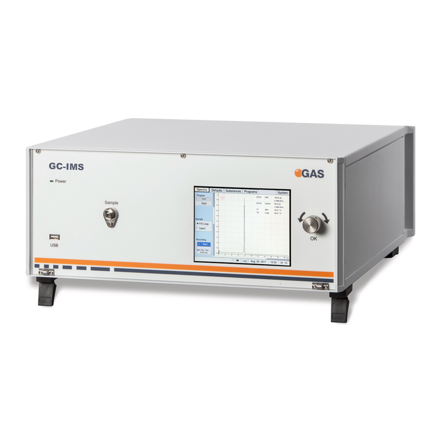
GC-IMS – User Manual 5.4 GC-IMS Housing Device Versions 5.4.1 GC-IMS 5.4.1.1 Front Figure 8: GC-IMS - Housing of device - Front • Power LED Indicates whether or not the device is connected to a power supply and is switched on •... -
Page 30: Rear
Input control for cycling through and activating the control elements of the graphical user interface. 5.4.1.2 Rear Figure 9: GC-IMS - Housing of device - Rear Power Switch Switches the device on or off. DC-In Socket 24V XLR-Connector for connecting the power supply. - Page 31 Drift Gas In Socket 3 mm Swagelok inlet plug for connecting the device to a drift gas source. Carrier Gas In Socket 3 mm Swagelok inlet plug for connecting the device to a drift gas source.
-
Page 32: Gc-Ims With Circular Gas Flow Unit
GC-IMS – User Manual 5.4.2 GC-IMS with Circular Gas Flow Unit 5.4.2.1 Front Figure 10: GC-IMS with Circular Gas Flow Unit - Housing of device - Front • Power LED Indicates whether or not the device is connected to a power supply and is switched on •... - Page 33 GC-IMS – User Manual Sample in socket 3 mm Swagelok inlet plug for connecting the device to a gas source via • Bypass Adapter • Transfer-line or • Luer-Lock-Adapter. Touch screen Display Displays the graphical user interface and allows the control of the device by touch screen.
-
Page 34: Rear
GC-IMS – User Manual 5.4.2.2 Rear Figure 11: GC-IMS with Circular Gas Flow Unit - Housing of device - Rear Power Switch Switches the device on or off. Signal Converter –I/O Socket for connecting a PLC Socket (Programmable Logic Controller) or other devices. - Page 35 Gas Out Socket 3 mm Swagelok plug for connecting the device to Drift Gas In Socket / Carrier Gas In Socket of GC-IMS Gas In Socket 3 mm Swagelok plug for connecting the...
- Page 36 GC-IMS – User Manual Device Type/Serial Displays manufacturer identification, Number Plate device type, serial number and version. 36/214...
-
Page 37: Gc-Ims With Airsense Μtd
GC-IMS – User Manual 5.4.3 GC-IMS with Airsense µTD 5.4.3.1 Top Figure 12:GC-IMS with Airsence µTD - Housing of device - Top • Mounting plate for placing the µTD µTD Mounting Plate Unit 37/214... -
Page 38: Front
GC-IMS – User Manual 5.4.3.2 Front Figure 13: GC-IMS with Airsense µTD - Housing of device - Front • Power LED Indicates whether or not the device is connected to a power supply and is switched on • Indicates an internal system error. - Page 39 GC-IMS – User Manual Touch screen Display Displays the graphical user interface and allows the control of the device by touch screen. Pushable Rotary Knob Input control for cycling through and activating the control elements of the graphical user interface.
-
Page 40: Rear
GC-IMS – User Manual 5.4.3.3 Rear Figure 14: GC-IMS with Airsence µTD - Housing of device - Rear Power Switch Switches the device on or off. Signal Converter –I/O Socket for connecting a PLC Socket (Programmable Logic Controller) or other devices. - Page 41 TD Zero Gas 2 3 mm Swagelok inlet plug for connecting the device to the 3 mm Zero Gas 2 connector of the µTD. Sample Out Socket 3 mm Swagelok plug for connecting the device to an adequate laboratory waste gas ventilation system/fume hood.
-
Page 42: Device Type / Serial Number Plate
GC-IMS – User Manual Power Supply Socket Connector for connecting the µTD power supply Power Switch Switches the device on or off. 5.5 Device Type / Serial Number Plate Figure 15: Device Type / Serial Number Plate Manufacturer Type Name... - Page 43 GC-IMS – User Manual CE Marking CE, Communauté Européenne Instruments bearing this mark comply with the relevant European directives 43/214...
-
Page 44: Operating Interface
GC-IMS – User Manual 6 Operating Interface The graphical user interface of the device can be controlled by using the touchscreen in combination with the pushable rotary knob at the front of the device. The selected control (button, input field etc.) element is marked blue. To activate it the knob can be pressed. -
Page 45: Windows Selection Bar
GC-IMS – User Manual Window Selection Bar The main windows can be selected. The content of the selected main Window Display Area window will be displayed. Status messages and system Status Bar information are displayed. 6.1.1 Windows Selection Bar Figure 17: Operating Interface - Windows Selection Bar... -
Page 46: Windows Display Area
GC-IMS – User Manual In System Window system specific System Window Button information are displayed system specific settings and can be set. Errors Information Win In Error Information Window current dow Tab error information are displayed 6.1.2 Windows Display Area In Window Display Area the content of the following main windows is displayed: •... -
Page 47: View Control Bar
GC-IMS – User Manual LAN Connection Displays the current connection status: Section Connected: Disconnected: Displays the current log status. New entry: No modification: Log Section Selecting this button will open the Log Section Window with a chronical list of system events... -
Page 48: Low/High Pressure Control
GC-IMS – User Manual Horizontal Control Moves the horizontal position of the buttons display area on the screen left or right. Reduces or enlarges the view of the Zoom Control buttons display area on the screen 6.1.5 Low/High Pressure Control The device pressure is monitored. -
Page 49: High Pressure Error
GC-IMS – User Manual 6.1.5.2 High Pressure Error WARNING! High pressure can destroy the device. Figure 21: Operating Interface - High Pressure Alarm Box 1. If overpressure is detected, a visual and audible alarm is triggered immediately. At the same time all temperature controllers and flow controllers are switched off. -
Page 50: Spectra Window
GC-IMS – User Manual 6.2 Spectra Window 6.2.1 Overview After the device is switched on and the system start is completed the Spectra Window is displayed. In the Spectra Window the data acquisition can be controlled. The current spectrum is displayed. The Recording Mode can be activated. The selected measurement program can be started. -
Page 51: Measurement Modes
GC-IMS – User Manual The live monitoring of measurements can Recording Check Box be recorded manually. The available storage capacity in minutes is displayed. Displays the current selected Drift Drift Voltage Mode Voltage state (positive / negative). Displays the current temperature, flow Device Parameter and pressure values. -
Page 52: Manually Operated Measurement
GC-IMS – User Manual 6.2.2.2 Manually operated measurement To record a measurement manually the Recording button can be switched on. If recording is not active the button is set to START and the checkbox is grey. If recording is active the button is set to STOP and the checkbox is yellow. -
Page 53: Sequence Window
GC-IMS – User Manual 6.3 Sequence Window In Sequence Window Sequence files can be imported and started by clicking on the Start Button. The processing status of a user created sequence file can be watched: Figure 26: Operating Interface - Sequence Window... - Page 54 GC-IMS – User Manual Figure 27: Operating Interface - Sequence Window - Processing You will see the sequence being processed, one Sample after another. The time passed and the total time for each Sample are displayed, showing you the progress.
-
Page 55: Defaults Window
Figure 28: Operating Interface - Defaults Window Pressure display Displays the relative overpressure of the gas flow. EPC1 displays the current the overpressure of the drift gas flow. EPC2 displays the overpressure of the carrier gas flow. - Page 56 Drift Voltage polarity can be selected and switched (positive/negative). Flow display In Input Field Setpoint the flowrate of Drift gas (EPC1) and Carrier gas (EPC2) can be set. The current flowrates for Drift gas (EPC1) and Carrier gas (EPC2) are displayed.
-
Page 57: Drift Voltage
Above the spectra chart the flow rates of the drift and carrier gas controlled by the two electric pressure controllers (EPC 1 and EPC 2) and the temperatures of the heating elements of the device are managed. -
Page 58: Substances Window
This substance list is used for analysing the measurement data during a measurement program run. The result of this analysis is a subset of the substances in this list detected in the respective gas sample. It is stored along with the measurement data. -
Page 59: Managing Substance Entries
GC-IMS – User Manual Modbus Register opens the Modbus Register setup dialog. deletes set registers Substance Calibration Displays the substance specific Information Area calibration information such as used concentration range, average, intensity type, area, search ranges and the quantification model name. - Page 60 GC-IMS – User Manual Figure 34:Substance selection 2 In case that the average between System setting and Substance data is different the relevant substance entry is labeled red und marked with an error symbol. Figure 35: Substance selection 3 When the Enable Button for the selected substance is checked that substance entry will be included in the substance recognition process during the next measurement program run.
-
Page 61: Managing Modbus Tcp Setup
GC-IMS – User Manual 6.5.3 Managing Modbus TCP Setup GAS Devices can output their results via the Modbus TCP protocol. The Registers can be set up on your device’s Substances page. When selecting a substance from list on the left, information about it will be displayed on the right. This includes the registers it will be mapped to. - Page 62 GC-IMS – User Manual Since the size of a register is 16 bit, 32bit Integers will have to be split up into two separate registers with each containing a half of the bits. In Figure 39 you can see in what order the 32bit are split up.
-
Page 63: Substance Calibration Information Area
GC-IMS – User Manual 6.5.4 Substance Calibration Information Area Substance specific calibration information such as used Average, Intensity type, Area, Ranges and the Quantification model name of the selected Substance in the substance window are shown. Figure 40: Substance Calibration Information Area... -
Page 64: Recognised Substances Window
GC-IMS – User Manual Quant Model Name Displays the quantification model name of the actual substance calibration file. INFORMATION! All substance calibration information are part of the calibration file set in the G.A.S. software VOCAL. For detailed Information refer to the VOCAL Tutorials. -
Page 65: Programs Window
GC-IMS – User Manual 6.6 Programs Window 6.6.1 Overview In Programs Window user-defined measurement programs can be set and managed. Figure 42: Operating Interface - Programs Window All created programs are listed in this box Measurement Program by name. The highlighted program is List area selected for execution or modification. - Page 66 GC-IMS – User Manual Program Repetition The time interval for program repetitions Time can be set. Program Repetition The number of program repetitions can Rate be set. Average of the current selected program can be set. The current average is...
-
Page 67: Create Measurement Programs
GC-IMS – User Manual 6.6.2 Create Measurement Programs The Measurement Program List window displays all measurement programs currently existing. The measurement programs list can contain up to 100 entries. The current average value is part of the program name. The selected program can be edited. -
Page 68: Edit Measurement Programs
V1: Switch the Valve Position (open / close) R: Start / Stop recording spectra (rec / stop) E1: Flow rate control for EPC1 drift gas (0- 500 ml/min) E2: Flow rate control for EPC2 carrier gas (0- 150* ml/min) 68/214... - Page 69 GC-IMS – User Manual P1: The sample flow can be set in percent of the pump power (0- 100 Selected program action line End of Program line INFORMATION! The EPC2 maximum flow (carriergas) of 150 ml/min is restricted by the installed column dimemsions. It only can be attained if the standard column is installed (15 m length, 0.53 mm inner...
-
Page 70: Flow Ramps
Figure 46: Flow Ramps The E2 (carrier gas flow) value is initially set to 10ml/min. The flow is kept constant for one minute. Between runtime 1min – 5min the flow is linearly increased to the target value 100ml/min. In the following the flow is increased linearly to 150ml/min in one minute. - Page 71 GC-IMS – User Manual INFORMATION! Please make sure that default values of EPC1 and EPC2 (Default window) corresponds with the start value of E1 and E2 in the program, otherwise the reproducibility of the measurement cannot be guaranteed. INFORMATION! Make sure that the EPC2 start pressure is reached again at the beginning of the next program run.
-
Page 72: System Window
GC-IMS – User Manual 6.7 System Window In the System Window system specific information are displayed and can be set. Figure 47: Operating Interface - System Window Info Button Displays the System Information Window Plan Button Displays the Device Plan Window Settings Button Displays the Settings Window. -
Page 73: System Info Window
GC-IMS – User Manual 6.7.1 System Info Window Figure 48: Operating Interface - System Info Window Type Device type. Serial Device Serial Number. Version Current Firmware Version. Date Date of current Firmware Version. IP-address Displays the current IPv4-Address. Next Maintenance Displays the next maintenance date. -
Page 74: System Plan Window
GC-IMS – User Manual CGFU Maintenance Displays the next maintenance date (only if CGFU is connected!) 6.7.2 System Plan Window Figure 49: Operating Interface - System Plan Window Plan Displays an overview plan of the device 74/214... -
Page 75: System Settings Window
GC-IMS – User Manual 6.7.3 System Settings Window Figure 50: Operating Interface - System Settings Windows 1 IP Adress Displays the current set IPv4-Adress of the device. With Set-Button the IPv4- adress can be set Toggles between simplified and normal View view. - Page 76 GC-IMS – User Manual With Upgrade-Button a firmware Firmware upgrade can be performed from a connected USB volume. Display The display brightness and screen-saver time-out can be set. The behaviour of the cooling fan can be set. When the temperature inside the device reaches the temperature in the field Start the cooler fan starts working.
- Page 77 GC-IMS – User Manual The Manage Button opens the snapshot Snapshot window. User-specific target values can be set. A new snapshot can be recorded or can be imported Snapshot is a new function to allow automatic instrument performance checking Contamin Define the automatic search area for contamination.
- Page 78 Drift Volt.: Prepared for further use! Currently not in function! Drift Gas: Selection field for operating gas type. The value is stored with measurement file. Diagnostics: With Create and export file-Button an encrypted diagnostic file is created for diagnostic purposes by G.A.S..
-
Page 79: Snapshot Window
This automatic monitoring can recognize among other a System contamination, insufficient gas quality or system leaking. For this purpose, the following parameters are constantly cross-checked against the target- settings: •... - Page 80 GC-IMS – User Manual Figure 53: Operating Interface – Snapshot Window Checked values Area The checked Snapshot values (EPC2 Pressure; Rip Height, Rip-Position at 101,33 kPa, Rip-half-value width FWHM are displayed. The selected Snapshot values (EPC2 Edit Threshold Pressure; Rip Height, Rip-Position at 101,33 kPa, Rip-half-value width FWHM can be edited.
- Page 81 GC-IMS – User Manual Import Snapshot Button Import a Snapshot-file with prepared values by G-A.S. Done Button Closes the snapshot window 6.7.3.1.1 Snapshot window in detail The system is delivered with standard limits for EPC2-Pressure, RIP-Height, RIP Position at 101.33 kPa and FWHM. The upper and lower limits of these parameters r can be adjusted by the customer.
- Page 82 GC-IMS – User Manual Upper Limit The upper limit of the current recorded snapshot value (Example EPC2 pressure) is displayed. This limit can be specified by the user. Factory default limits Lower limit Upper limit Name EPC2-Pressure (kPa) RIP Height (V) RIP Position at 101.33 kPa (ms)
-
Page 83: Simplified View Window
GC-IMS – User Manual 6.7.3.2 Simplified View Window Figure 55: Operating Interface - Simplified View Window A measurement identification can be specified by the customer. Start Button By selecting this button the current program is started. 83/214... -
Page 84: System Transfer Window
GC-IMS – User Manual 6.7.4 System Transfer Window Figure 56: Operating Interface - System Transfer Window MEA Files: The current number of internal stored measurement files and the following measurement file managing options are displayed and available: Copy to USB: Copy all internal stored measurements to a connected USB device. - Page 85 GC-IMS – User Manual Protocol: Displays the current used transfer protocol (smb, sftp or tftp). User: Displays the current used user name. Export: Displays the current used IPv4-address. Sharename: Displays the current used sharename of the storage folder. With Current Connection button the...
-
Page 86: System Modes Window
GC-IMS – User Manual 6.7.5 System Modes Window Figure 57: Operating Interface - System Modes Window Trigger mode: Activate trigger mode with Start. Remote mode: Activate remote mode with Start. Cleaning: Setup and activate of cleaning mode. With Start-Button the cleaning process is activated and the Cleaning Mode Window appears. -
Page 87: Trigger Mode Window
GC-IMS – User Manual With Enable-Button the access to the Inspection inspection and diagnostic functions of the device is allowed. 6.7.5.1 Trigger Mode Window Figure 58: Operating Interface - Trigger Mode Window Program Start Area In Trigger mode the displayed program is started by a connected device (e.g. -
Page 88: Remote Mode Window
GC-IMS – User Manual 6.7.5.2 Remote Mode Window By activating the Remote Mode, the Remote Mode Window appears. The windows is initially empty. The device is waiting for a sequence file to import. INFORMATION! The sequence file must be created with the G.A.S. Sequence Designer Software. -
Page 89: Cleaning Mode Window
GC-IMS – User Manual 6.7.5.3 Cleaning Mode Window By activating the Cleaning Mode, the Cleaning Mode Window appears. During the cleaning process the available system temperatures (T1-T6) are heated up to their maxima. The user default flow rates settings for Driftgas (EPC1) and Carriergas (EPC 2) setup in Defaults window are used. -
Page 90: Standby Mode Window
By activating the Standby Mode, the Standby Mode Window appears. The flowrate of the Drift gas (EPC1) and the carrier gas (EPC2) will be decrease to reduce gas consumption. The standby mode flowrate for drift gas (EPC1) is 10 ml/min and for carrier gas (EPC2) is 5 ml/min. -
Page 91: Error Information Window
GC-IMS – User Manual 6.8 Error Information Window In case if an Error the !-Tab is blinking red. The error window shows an overview of the current error events. When the device is restarted, the error events are deleted. Figure 62: Error Information Window Selection Sort Order Bar Selects the following sort order: Current;... -
Page 92: Additional Dialog Windows
GC-IMS – User Manual 6.9 Additional Dialog Windows 6.9.1 Log Messages Dialog Window Figure 63: Log Messages Dialog Window Entry List A chronological list of system event messages. Warnings are marked orange, error messages are marked red. To Last Entry Button Scrolls down to the latest entry. -
Page 93: Ip Adress Input Dialog Windows
GC-IMS – User Manual 6.9.2 IP Adress Input Dialog Windows The IP Address Input Dialog is used to edit the static IP address of the device and the IP address of a remote server. This is necessary when configuring the LAN file transfer. -
Page 94: Date And Time Input Dialog Window
GC-IMS – User Manual 6.9.3 Date and Time Input Dialog Window Figure 65: Date and Time Input Dialog Window Date Fields Fields displaying and modifying day, month and year. Time Fields Fields displaying and modifying hours, minutes and seconds. Timezone Field for selection of timezone. -
Page 95: Text Input Dialog Window
GC-IMS – User Manual 6.9.4 Text Input Dialog Window The Text Input Dialog is used to enter identifiers, e.g. shared folder name. Figure 66: Text Input Dialog Window Clear Button Deletes the text in the current text field Keyboard Buttons Character and control buttons for entering a text. -
Page 96: Number Input Dialog Window
GC-IMS – User Manual 6.9.5 Number Input Dialog Window The Number Input Dialog is used in Program Window to enter number values, e.g. Start time, Flow Rates and Pump Power setpoints in Program Actions. Figure 67: Number Input Dialog Window (Example) Range / Raster Info Displays the valid value range. -
Page 97: Installation Gc-Ims Device
• Stainless steel pressure reducer with adjustable pressure range of 3 – 6 bar and 3 mm Swagelok connector Safety • Availability of exhaust system for device exhaust gas tubes (Gas out and Sample Gas out) Computer • Computer with current Microsoft Windows operating system •... -
Page 98: Installing The Device (Gc-Ims Basic)
To ensure correct measurements it is absolutely necessary to connect the supplied exhaust tubes (Gas out and Sample gas out). The exhaust tubes (Gas out and Sample gas out) must be led separately into the exhaust system and must not be connected. - Page 99 Remove protective caps from molecular sieve. Retain for future use. INFORMATION! Protective caps should be put on gas sockets in case the device is stored or transported. WARNING! It is absolutely necessary to remove all protective caps before the system is switched on.
- Page 100 PFA tube. INFORMATION! Recommended pressure of Operation Gas (Driftgas / Carriergas) is 3 bar (300 kPa). 6 bar (600 kPa) must not be exceeded. Connect the Driftgas-/ Carriergas-Adapter to the Driftgas- and the Carriergas-Connector.
- Page 101 To ensure correct measurements it is absolutely necessary to connect the supplied exhaust tubes (Gas out and Sample gas out). The exhaust tubes (Gas out and Sample gas out) must be led separately into the exhaust system and must not be connected.
- Page 102 GC-IMS – User Manual For the output of concen- tration values through the 0-20 mA current loop connect an appropriate Option cable to the Signal Converter – I/O Ports socket. For file transfer via LAN: Connect the Ethernet socket with an...
-
Page 103: Installing The Device (Gc-Ims With Cgfu)
GC-IMS – User Manual 7.3 Installing the device (GC-IMS with CGFU) Unpack the device. Remove the foam spacers. Remove the accessories boxes. Lift the device from the transport box. WARNING! Do not deploy the device in areas exposed to explosive substances or... - Page 104 Retain for future use. INFORMATION! Protective caps should be put on gas sockets in case the device is stored or transported. WARNING! It is absolutely necessary to remove all protective caps before the system is switched on.
- Page 105 GC-IMS – User Manual Connect CGFU- Connection-Cable. (normally pre-installed!) INFORMATION! Only use PFA tubes with 3 mm outer diameter and 3 mm Swagelok connectors. Screw on the Swagelok caps manually and fix them by screwing a further half-turn using a 12 mm open-end wrench.
- Page 106 Connect socket Sample Out to appropriate waste gas ventilation system. INFORMATION! To ensure correct measurements it is absolutely necessary to connect the supplied exhaust tubes (Sample gas out). The exhaust system must not generate any negative pressure. Switch on device. 106/214...
- Page 107 GC-IMS – User Manual Connect a sample gas source to socket Sample In with the delivered bypass adapter. For the output of concen- tration values through the 0-20 mA current loop connect an appropriate Option cable to the Signal Converter – I/O Ports socket.
-
Page 108: Installing The Device (Gc-Ims With Airsense Μtd)
GC-IMS – User Manual 7.4 Installing the device (GC-IMS with Airsense µTD) Unpack the device. Remove the foam spacers. Remove the accessories boxes. Lift the device from the transport box. WARNING! Do not deploy the device in areas exposed to explosive substances or... - Page 109 Remove protective caps from molecular sieve. Retain for future use. INFORMATION! Protective caps should be put on gas sockets in case the device is stored or transported. WARNING! It is absolutely necessary to remove all protective caps before the system is switched on.
- Page 110 Connect nitrogen gas (Purity 5.0 or better) source to input of supplied molecular sieve using a PFA tube. INFORMATION! Recommended pressure of Operation Gas (Driftgas / Carriergas) is 3 bar (300 kPa). 6 bar (600 kPa) must not be exceeded. 110/214...
- Page 111 To ensure correct measurements it is absolutely necessary to connect the supplied exhaust tubes (Gas out and Sample gas out). The exhaust tubes (Gas out and Sample gas out) must be led separately into the exhaust system and must not be connected.
- Page 112 Driftgas- / Carriergas-Adapter using a 3 mm Swagelok PFA tube. Also connect Outlet ZeroGas 2 and TDZero Gas 2 using a 3 mm Swagelok PFA tube. For further Information see: Airsense µTD manual Connect GC-IMS Signal Converter I/O-Port to µTD Digital Port with...
- Page 113 GC-IMS – User Manual Connect the µTD detector transfer line to sample in socket of GC- IMS. Connect the µTD sampling transfer line to µTD. Connect a sample gas source to sampling transferline with the delivered bypass adapter. Switch on both devices.
- Page 114 For detailed information about the installation and operation of the µTD please refer the µTD-GC-IMS Quickstart Manual and the Airsense µTD Manual. INFORMATION! When the µTD unit is connected to GC-IMS, the current loop data output cannot be used. 114/214...
-
Page 115: Prepare The Device For Operation
GC-IMS – User Manual 7.5 Prepare the device for operation Before using the device for the first time or after being disconnected from the nitrogen source for some time it must be cleaned to ensure proper operating conditions. In this case start the cleaning mode. - Page 116 GC-IMS – User Manual Select duration in hours: System › Modes › Cleaning Mode › x h Option To speed up this process, increase flow rate of EPC1 and EPC2 to their maximum values (e.g Option 500/150 ml/min): Defaults › EPC1 › EPC2 Start cleaning: System ›...
- Page 117 GC-IMS – User Manual Wait until cleaning process is completed. The process can be stopped with Skip. After all temperatures reached the default values inspect visually the current spectrum and compare it with the reference spectrum of the analytical approval. The...
-
Page 118: System Operation
8.1.1 Measurement Reqiurements INFORMATION! Only use the original accessories supplied with the device. INFORMATION! Make sure that the gas quality is 5.0 (99,999%) or better. INFORMATION! Only use stainless steel pressure reducer. INFORMATION! Make sure that the spectrum is clean a without contamination. -
Page 119: Workflow: Sampling Methods And Measurement Start
GC-IMS – User Manual 8.1.2 Workflow: Sampling methods and measurement start INFORMATION! The following workflow shows the exemplary measurement procedure. Standard Sampling method 1 (Bypass sampling): Connect a Bypass- Adapter to Sample-In- Connector at the front of the Device. Connect a Sample-Gas-Supply to Bypass-Adapter. - Page 120 GC-IMS – User Manual Sampling method 2 (Direct sampling): Connect a Sample-Gas- Supply to Sample-In- Option Connector at the front of the Device. Make sure that the sample source gas is pressure- free. Check and setup the measurement parameter. Make sure that that all...
- Page 121 GC-IMS – User Manual Sampling method 3 Sampling with Luer Adapter: Connect a Luer-Adapter Option to Sample In Connection at the front of the Device. Check and setup the measurement parameter. Make sure that that all temperature-, flow- and Option...
- Page 122 GC-IMS – User Manual Sampling method 4 Sampling with µTD device: Connect the Sample-Gas- Option Out-Tube of the µTD device to Sample-In- Connector at the front of the Device. Check and setup the measurement parameter. Make sure that that all...
- Page 123 GC-IMS – User Manual system Trigger Mode: System › Modes › Start Option Select a measurement program: Programs › Select Start current measurement program: Spectra › Start INFORMATION! The maximum measuring time is limited to 59 minutes 59 seconds and 980 milliseconds.
-
Page 124: Workflow: Manual Mesasurement Recording
GC-IMS – User Manual 8.1.3 Workflow: Manual Mesasurement Recording To record a measurement manually select: Spectra › Recording- Start To stop the measurement select: Spectra › Recording- Stop INFORMATION! The maximum measuring time is limited to 59 minutes 59 seconds and 980 milliseconds. -
Page 125: Workflow: Create A Measurement Program
GC-IMS – User Manual 8.2 Workflow: Create a Measurement Program Select: Programs To create a new program select the Button Enter a new program name or use the default name. The program end time is displayed as the final line... - Page 126 GC-IMS – User Manual To create a new program action line select the Button This line can be filled with values. For more information see also Chapter 6.6.3 Edit Measurement Programs After the necessary values have been entered, repeat step 4 and 5 to create the next program action line.
-
Page 127: Workflow: Start Sequence
GC-IMS – User Manual A complete program sequence can be created line by line. INFORMATION! The device is delivered with standard programs that can be adapted to your needs. Customer-specific programs can also be created optionally. 8.3 Workflow: Start Sequence INFORMATION! The sequence file must be created with the G.A.S. - Page 128 GC-IMS – User Manual Select the import location pf the sequence file named Sequence.json The Sequence will be executed. INFORMATION! The file has to be named Sequence.json for the software to recognize it. Make sure, that the parameters specified in the programs and after- run settings are within your devices permitted regions.
-
Page 129: Workflows: File Transfer Setup
GC-IMS – User Manual 8.4 Workflows: File Transfer Setup 8.4.1 Overview Files can be transferred to and from the device by LAN connection and by USB device connected to the USB port at the front of the housing. INFORMATION! A connected USB device is always preferred to a LAN connection when exporting or importing files manually. -
Page 130: Connecting To A Server In A Lan
GC-IMS – User Manual 8.4.2 Connecting to a Server in a LAN INFORMATION! Some PC Ethernet interfaces may not be suited for a direct connection to the device. In that case consider using an Ethernet switch to connect both devices. - Page 131 GC-IMS – User Manual For SFTP set up a SFTP server. Consult your system administrator on how to do that. Option For an example SFTP ® server for Microsoft ® Windows PCs see: http://www.coreftp.com/s erver For TFTP install the G.A.S. IMS-Control TFTP- Server on the PC.
- Page 132 GC-IMS – User Manual INFORMATION! Note that both devices must be in the same subnet mask area of 255.255.255.0 i.e. only differ in the fourth number of the four-part IPv4 address. System › Transfer Open Activate or deactivate automatic file transfer to the server with Automatic Export.
- Page 133 GC-IMS – User Manual Select the desired protocol SMB, SFTP or TFTP. For SMB enter Server IP Address, Folder name, User name and Password for the SMB share on the Option server. 133/214...
- Page 134 GC-IMS – User Manual For SFTP enter Server IP Address, IP Port, User name and Password for the SFTP server. Option For TFTP enter the Server IP Address. Option Test the connection with Test Connection. 134/214...
- Page 135 GC-IMS – User Manual INFORMATION! When the connection cannot be established check the Ethernet cable connection. Main the network IP address of the server, the used protocol, the name of the shared folder (SMB) on the server and the server account login data (SMB, SFTP). Consult the manuals of your server operating system and your system administrator.
-
Page 136: Workflow: Manual Transfer Of Measurement Files To Usb-Stick
GC-IMS – User Manual 8.4.3 Workflow: Manual Transfer of measurement files to USB-Stick INFORMATION! Do not turn off the device during the download process! Connect the USB device (FAT32-formatted) to the USB socket at the front side of the housing. - Page 137 GC-IMS – User Manual Wait until the exporting process is completed. A confirmation dialog opens. Press OK to unmount the USB-Stick Remove the connected USB device from the USB socket at the front side of the housing. The measurement files has been downloaded.
- Page 138 GC-IMS – User Manual 8.4.4 Workflow: Manual Transfer of measurement files to connected server INFORMATION! Do not turn off the device during the download process! Open page: System › Transfer. Press: Copy Remote . A confirmation dialog opens. Select the storage location.
- Page 139 GC-IMS – User Manual Wait until the exporting process is completed. The measurement files has been downloaded. 139/214...
-
Page 140: Workflow: Current Loop Setup
GC-IMS – User Manual 8.5 Workflow: Current Loop Setup 8.5.1 Indroduction The device writes the measured concentration of the main substance as electrical current to the 0-20 mA-current loop interface. The concentration range of the output substance is mapped to a sub-interval within 0-20 mA. - Page 141 GC-IMS – User Manual Open dialog: Substances › Current Loop Settings. Optional open dialog: System › Settings › Settings. Option Select Loop 1 or Loop 2. loop1: Output of the first substance result. Loop2: Output of the second substance result.
- Page 142 GC-IMS – User Manual In Projection: User Value -> Current set Min and Max value of the concentration range to the range 0 mA – 20 mA. In Calibration: Current -> DAC set DAC [0 mA] and DAC [20 mA] calibrate to...
- Page 143 GC-IMS – User Manual When desired set mA values for error and idle state with Projection User Value -> Current Error and Idle. Close the dialog with Set. 143/214...
-
Page 144: Workflow: Modbus Tcp Setup
GC-IMS – User Manual 8.6 Workflow: Modbus TCP Setup Open dialog: Substances › Import to import a substance file list named calibration.gsd Select a Substance to setup the Modbus TCP register. Select Set register to open the Setup Dialog. 144/214... - Page 145 GC-IMS – User Manual In Setup Dialog enter the Register Values. In Substances Window the entered Register range is displayed. 145/214...
-
Page 146: Workflow: Start Cleaning Mode
GC-IMS – User Manual 8.7 Workflow: Start Cleaning mode INFORMATION! In case of contamination it is helpful to activate the cleaning mode to clean the system. In case of contamination it is helpful to activate the cleaning mode to clean the system. -
Page 147: Workflow: Start Standby Mode
GC-IMS – User Manual 8.8 Workflow: Start Standby mode INFORMATION! It is recommended not to switch off the device during measurement breaks. Using the Standby mode ensures the cleanness of the system and a quick readiness to measure. Select System › Modes ›... -
Page 148: Workflow: Remove The Housing Cover
GC-IMS – User Manual 8.9 Workflow: Remove the Housing Cover DANGER! Before all work on the device switch off the device and pull out the power plug! Switch off the device and pull out the power plug. Open the side-covers of the case carefully using a screwdriver. - Page 149 GC-IMS – User Manual Removed side-cover. Open the top-cover of the case carefully using a screwdriver. Remove the top-cover of the case carefully 149/214...
- Page 150 GC-IMS – User Manual Device without top cover. 150/214...
-
Page 151: Workflow: Change Capillary Column
GC-IMS – User Manual 8.10 Workflow: Change Capillary Column DANGER! Before all work on the device switch off the device and pull out the power plug! Necessary tools: 1. Small slotted screw driver 2. T10 Torx screwdriver 3. 8mm wrench 4. - Page 152 GC-IMS – User Manual Remove the top cover. For detailed information Workflow: Remove Housing Cover Release all screw of the oven-cover and remove it. Release all screw of the inner oven-cover and remove it. 152/214...
- Page 153 GC-IMS – User Manual Open the capillary-column- connectors using a 8 mm open-end-wrench. Open the capillary-column- connectors using a 8 mm open-end-wrench. Also open the transfer line securing holder. Remove the capillary column. Remove the blind bolts (1) + (2) of the capillary...
- Page 154 GC-IMS – User Manual Insert the 1/16“ screw connectors und the Teflon- ferrules with hole. Ensure that the distance between ferule and column end is about 5 Put the new capillary column into the oven. If necessary cut the ends of the column.
- Page 155 GC-IMS – User Manual Connect the capillary- column-connector using two 8 mm open-end- wrench. Also close the transfer-line securing holder. Mount the screws of the inner oven cover. Make sure that the column labeling is screwed on. Mount the screw of the oven cover.
-
Page 156: Workflow: Change Sample Pump Unit
GC-IMS – User Manual 8.11 Workflow: Change sample pump unit INFORMATION! Only authorized, trained and technically instructed people are allowed to do these work steps. DANGER! Before all work on the device switch off the device and pull out the... - Page 157 GC-IMS – User Manual Top view of installed sample pump unit. Remove the plug. Loosen front connector. 157/214...
- Page 158 GC-IMS – User Manual Loosen rear connector. Loosen the fixing screws and remove the sample pump unit. Insert a new sample pump unit and mount it in reverse order. 158/214...
-
Page 159: Workflow: Change High Voltage Circuit Board
GC-IMS – User Manual 8.12 Workflow: Change high voltage circuit board INFORMATION! Only authorized, trained and technically instructed people are allowed to do these work steps. DANGER! Before all work on the device switch off the device and pull out the... - Page 160 GC-IMS – User Manual Remove the top cover. For detailed information Workflow: Remove Housing Cover Open the front panel. Loosen four srews with T8 screwdriver and remove the coverplate. 160/214...
- Page 161 GC-IMS – User Manual Loosen the nut from transmitter and pull out fibre-optical-cable. Push the button and pull out high voltage wire Push the button and pull out ground wire Pull the circuit board out of the casing profile 161/214...
- Page 162 GC-IMS – User Manual Insert the new circuit board Push the button and reinsert the ground wire Push the button and reinsert the high voltage wire Reinsert the optical fiber cable and tighten the screw connection. 162/214...
- Page 163 GC-IMS – User Manual View of the three connected wires. Replace the cover plate and tighten the four screws. Close the front plate and attach the top cover.. 163/214...
- Page 164 GC-IMS – User Manual Tighten the three screws of the frontplate. 164/214...
-
Page 165: Workflow: Reinitialize The 6-Port-Valve
GC-IMS – User Manual 8.13 Workflow: Reinitialize the 6-Port-Valve INFORMATION! Only authorized, trained and technically instructed people are allowed to do these work steps. DANGER! The device must be operated in the open state. Be very careful! Remove the top cover. - Page 166 GC-IMS – User Manual Valve position Fill Loop: Controller LED in POS-A Valve position Fill Loop: Controller LED in POS-B Switch Valve to position Fill Loop Disconnect the five-pin plug of the valve controller. 166/214...
- Page 167 GC-IMS – User Manual Switch the valve as long as both controller LEDs are off. The valve is now in initialization mode. Replug the five-pin connector of the valve controller. Switch valve about eight times between position Fill Loop and Inject.
-
Page 168: Workflow: (Optional) Change Filter Set Cgfu
If the valve cannot find a position or the switching noise does not return to normal, repeat the procedure. 8.14 Workflow: (Optional) Change filter set CGFU INFORMATION! It is recommended change the filter set of the Circular gas flow unit periodically. The recommended maintenance interval is every 6 month. DANGER! - Page 169 GC-IMS – User Manual Remove the side-covers of the CGFU-case carefully with a small screwdriver and remove the cover. The two molecular sieve cartridges (Red) and the activated carbon cartridge (Black) must be replaced periodically every 6 month. Loosen the connectors...
-
Page 170: Workflow Firmware Upgrade
The firmware of G.A.S. IMS devices can be upgraded by the user with an upgrade file – named update.gas - provided by G.A.S. This file has to be put on an empty USB storage device (e.g. ‘USB stick’ / ‘USB thumb drive’) formatted as a FAT32 file system. - Page 171 GC-IMS – User Manual INFORMATION! Do not turn off the device during the upgrade process! Connect the USB device (FAT32-formatted) with the upgrade file – named update.gas - provided by G.A.S. to the USB socket at the front side of the housing.
- Page 172 GC-IMS – User Manual Wait for the device to restart or press Skip to restart the device immediately. Now: Remove the connected USB device from the USB socket at the front side of the housing. Wait until the device has...
-
Page 173: Workflow: Creating Diagnostic Information For Support
GC-IMS – User Manual 8.16 Workflow: Creating diagnostic information for support INFORMATION! The following steps are necessary to compile the required diagnostic information. Please stick on consecution as listed below. Take a picture of the instrument label on the rear side. - Page 174 GC-IMS – User Manual Insert a FAT32 formated USB-stick into the USB slot at the front of the device. In System Window > Transfer select Settings and start the diagnostic file compilation by selecting the Create and Import file Button.
- Page 175 GC-IMS – User Manual Select Export Location /USB/ and press OK. Send the diagnostic file and the photos taken by user by data transfer to [email protected] 175/214...
-
Page 176: Workflow: Packing For Return Transport
GC-IMS – User Manual 8.17 Workflow: Packing for return transport INFORMATION! It is recommended to use the original transport box for a safety return transport. INFORMATION! It is recommended to to send the transport box on palett for a safety return transport. - Page 177 GC-IMS – User Manual Minimum scope of delivery for the return transport: Device 1, Hoses 2, power supply 3 and plug 4 It is recommended to return the system in the original box and on palett. Further accessories can be supplied optionally.
-
Page 178: Workflow: Manual Modification Of The Sample Description Attribute
GC-IMS – User Manual 8.18 Workflow: Manual modification of the sample description attribute. The attribute sample description can be changed manually in the measurement file. For this purpose a text editor is required, e.g. the free editor Notepad++ [https://notepad-plus-plus.org/]. INFORMATION! Only authorized, trained and technically instructed people are allowed to do these work steps. - Page 179 GC-IMS – User Manual With right click on measurement file select Edit with Notepad++. In the opened measurement file find the attribute Sample. Change sample description (Entry between the quotation marks). Save the measurement file. 179/214...
-
Page 180: Appendix
GC-IMS – User Manual 9 Appendix 9.1 Technical data: GC-IMS • Housing: 19”-compatible Dimensions • Height: 184.5 mm • Width: 449 mm • Depth 435 mm • Weight: ca. 15 kg • Temperature range: +5 °C … +40°C Operational conditions •... - Page 181 GC-IMS – User Manual • Sample-Rate: 150 kHz Data aquistion • Resolution: 14 bits • Trigger-duration: 100 µs • Trigger-repetition rate: 30 ms • Transimpendance: 3 V/nA typ. • 2,7 kV Positive/negative Driftvoltage Drift voltage switchable • 6-port-valve Sampling system •...
- Page 182 • Output Pressure Stability: 0.01% • Output Pressure Linearity: 0.05% • Operation flow rates: 0 – 150 mL/min (depending on the GC-Column dimensions) • Gas nitrogen 5.0 quality or Synthetic air 5.0 Consumables quality • IMS, column and sampling system are Cleaning mode heated up to >...
-
Page 183: Technical Data: I/O Interface
GC-IMS – User Manual 9.2 Technical data: I/O Interface Device Connector Specification Analog Output type Isolated active current output output Non-loaded voltage 0-22 mA Maximum output signal < 20 V Maximum output load (burden < 25 mA resistance) 500 Ohm Accuracy better than 0.5 %... - Page 184 GC-IMS – User Manual Device Connector Pinout Connector D-Sub DA-15 female type Analog Return Pin 1 output Output #2 Pin 2 Output #1 Pin 9 ____________________ Pin 1 is common return for both analog outputs and for the digital transistor output...
- Page 185 MessageBox with Time(s) of occurrence is displayed and must be confirmed. • None Error output via current loop or digital output. Only via Modbus, a bit is set for "external error" (error codes) at current measurement. • On the GC-IMS the current measurement remains unaffected by this. 185/214...
-
Page 186: Ionisiation Source Specification
GC-IMS – User Manual 9.3 Ionisiation Source Specification INFORMATION! The permission and exemption limits are regulated by the Radiation Protection Ordinance and the European Union Council Directive 96/26/EURATOM in accordance with the regulations of the International Atomic Energy Authority (IAEA). - Page 187 GC-IMS – User Manual Below the exemption limit of a dose rate of 1 µSv/h at a distance of 0.1 m from any accessible surface of the apperatus acc. to Article 26, of the Directive 2013/59 EURATOM of December 5...
-
Page 188: Technical Drawing: Internal Gasflow
GC-IMS – User Manual 9.4 Technical drawing: Internal Gasflow 188/214... -
Page 189: Current Loop Interface
GC-IMS – User Manual 9.5 Current Loop Interface Output Type Isolated active current output 0-20 mA Non-loaded Voltage < 20 V < 22 mA Maximum Output Signal 500 Ohm Maximum Output Load (burden resistance): Accuracy Better than 1 % D-Sub DA-15 female... -
Page 190: Modbus Tcp Specification
GC-IMS – User Manual 9.6 Modbus TCP Specification Register Layout Offset Register Content 40001-40006 Header Information for the latest results. 7-125 40007-40125 The latest results are mapped to these registers. 126-132 40126-40132 Header information for the previous results 133-250 40133-40250 The previous results are mapped these registers. - Page 191 GC-IMS – User Manual Unused Substance at Register n Register Datatype Information 32bit unsigned Integer The concentration (multiplied by 1000 for a possible three decimal point precision) encoded into a 32bit Integer split up into this and the following register.
- Page 192 GC-IMS – User Manual Error codes Value Information No Error Unknown Error. Source of Error unknown. Error concerning current. Only used in special applications. The temperature of a component has not reached the designated value The flow of one or more...
-
Page 193: Troubleshooting
GC-IMS – User Manual 9.7 Troubleshooting 9.7.1 Error message list Error message Drift voltage supply. Description Drift voltage error Action Fatal Error! Contact the G.A.S. service hotline. Can’t save measurement. Error message Description The measurement file could not be saved to the internal memory. - Page 194 G.A.S. service hotline. Drift gas flow too low. Aborting… Error message Description At program start the drift gas flow is too low. Programstart will be refused. Action Increase the back pressure. Repeat the procedure. If that still does not help contact the G.A.S.
- Page 195 GC-IMS – User Manual Action Fatal Error! Contact the G.A.S. service hotline. Error message Invalid program. Description The selected program has no instructions. Action Complete the program and repeat the procedure. If that still does not help contact the G.A.S. service hotline.
- Page 196 GC-IMS – User Manual If that still does not help contact the G.A.S. service hotline. Error message No measurements stored. Description No measurements stored on the internal storage. Action Do a measurement. Repeat the procedure. If that still does not help contact the G.A.S.
- Page 197 GC-IMS – User Manual Action Do a measurement. Repeat the procedure. If that still does not help contact the G.A.S. service hotline. Error message RTC read error. Description Date and time setting failed. Action Restart the system and repeat the procedure.
- Page 198 GC-IMS – User Manual Error message Can't set static ip! Description Setup of the static IP-address failed. Action Check the network settings. Contact your adminstrator. Repeat the procedure. If that still does not help contact the G.A.S. service hotline. Error message...
- Page 199 GC-IMS – User Manual Error message Select program first. Description When starting the trigger mode no program is activated. Action Select a program and repeat the procedure. If that still does not help contact the G.A.S. service hotline. Can’t read calibration.gsd...
-
Page 200: Ims-Spectrum Examples
GC-IMS – User Manual 9.7.2 IMS-Spectrum Examples Schematic of IMS Spectrum reasons / suggestions spectrum description Clean spectrum Perfect Clean spectrum, up to two extra signals left Perfect hand side of the RIP RIP shifted to lower - elevated temperature... - Page 201 GC-IMS – User Manual - gas quality out of Minor impurities specifications - device is polluted > run system cleaning - gas quality out of Major impurities specifications - device is polluted > run system cleaning Elevated noise Contact G.A.S. support No signal Contact G.A.S.
-
Page 202: Troubleshooting / How To
Wait up to 5 min. Normally the start procedure continues. Restart the system. If that still does not help contact the G.A.S. service hotline. Symtom Temperature and/or gas flow values will not be displayed Possible Cause Problem with hardware/firmware communication Action Restart the system. - Page 203 Possible Cause Hardware failure Action Contact the G.A.S. service hotline. Symtom No or small Reaction Ion Peak (RIP) will be displayed. Possible Cause Insufficient gas quality Action Check quality of operating gas (5.0 or better) and use moisture trap. 203/214...
- Page 204 GC-IMS – User Manual Action When using the CGFU-unit, replace the CGFU- filters. Possible Cause System contamination Action Start cleaning mode. Symtom Find signals from the prior measurement run in the chromatogram Possible Cause The measurement runtime is too short.
- Page 205 If that still does not help change sample pump. Symtom Drift time fluctuates Possible Cause System is untight Action Check all gas supply connections of operating gas. Action Check all gas supply connections of GC- column. Symtom Retention time fluctuates...
-
Page 206: Consumables / Spare Parts
GC-IMS – User Manual 9.8 Consumables / Spare Parts Part number: 4000 1000 Power supply with Power plug Part number: 9510 0000 Gas tube Kit: (GC-IMS) • Driftgas/Carriergas Adapter • 2 m 3mm PFA Tubes with 3 mm Swagelok-Connector (6 Pieces) •... - Page 207 GC-IMS – User Manual Part number: 8101 1524 Standard-capillary column MXT-5 Lenght 15 m, ID 0,53 mm, Filmthickness 1 µm, Winding ID 80 mm (Other column types only on request) Part number: 8103 1001 Teflon Ferrules for capillary column with ID 0,53 mm Connection 1/16", Hole 0,8mm, T max.
- Page 208 Torx Tool Kit • Torx Screwdriver 8 mm (1 piece) • Torx Screwdriver 10 mm (1 piece) Part number: 8001 1707 GC-IMS Transport box Length = 75 cm, Height = 30 cm, Width = 59 cm (1 piece) Part number: 8003 0001...
- Page 209 GC-IMS – User Manual Part number: 4600 000 000 Circular Gas Flow Unit with accessories Part number: 8900 1104 Circular Gas Flow Unit exchange filterset. Part number: 4000 0930 Circular Gas Flow Unit pump. Part number: 4600 500 000 Nitrogen Generator with accessories...
- Page 210 GC-IMS – User Manual Part number: 8204 1100 µTD with accessories Part number: 8205 0000 Laptop Computer (different design) including software for control and evaluation Part number: 4000 2130 Luer Adapter (1 piece) Part number: 4000 2100 Luer Adapter Heater (1 piece)
-
Page 211: Corresponding G.a.s. Documents And Tutorials
9.9 Corresponding G.A.S. Documents and Tutorials INFORMATION! • GC-IMS Quickstart Manual • CGFU User Manual (optional) • Airsense uTD Handbook (optional) • µTD GC-IMS Additional Information Quickstart (optional) • Sequence Designer Manual • IMS Control TFTP-Server Manual • Tutorials Sequence Designer 211/214... - Page 212 GC-IMS – User Manual • Tutorials VOCal • Manuals VOCal 212/214...
-
Page 213: Table Of Figures
Figure 9: GC-IMS - Housing of device - Rear ............30 Figure 10: GC-IMS with Circular Gas Flow Unit - Housing of device - Front .... 32 Figure 11: GC-IMS with Circular Gas Flow Unit - Housing of device - Rear ..... 34 Figure 12:GC-IMS with Airsence µTD - Housing of device - Top ...... - Page 214 GC-IMS – User Manual Figure 51: Operating Interface - System Settings Windows 1 ........75 Figure 52: Operating Interface - System Settings Window 2 ........76 Figure 53: Operating Interface - System Settings Windows 3 ........78 Figure 51: Operating Interface – Snapshot Window ..........80 Figure 52: Operating Interface –...