socomec ATyS t Instruction Manual
Automatic transfer switching equipment
Hide thumbs
Also See for ATyS t:
- Instruction manual (70 pages) ,
- Quick start (4 pages) ,
- Installation and operating manual (30 pages)

Related Manuals for socomec ATyS t


Summary of Contents for socomec ATyS t
- Page 1 _________ l � -' -------- - - Автоматический реверсивный рубильник Socomec ATyS t - руководство по эксплуатации. Юниджет Постоянная ссылка на страницу: https://www.uni-jet.com/catalog/ustrojstva-avr/socomec- atys-t.html...
- Page 2 ATyS t Automatic Transfer Switching Equipment www.socomec.com...
- Page 3 To download, brochures, catalogues and technical manuals: This manual is available for download in French, English, German, Italian, Spanish, Dutch, Portugese, Russian, Polish, Turkish and Chinese. ATYS t - 541 995 D - SOCOMEC...
-
Page 4: Table Of Contents
.........31 ATYS t - 541 995 D - SOCOMEC... - Page 5 ..............58 ATYS t - 541 995 D - SOCOMEC...
- Page 6 ..........64 ATYS t - 541 995 D - SOCOMEC...
-
Page 7: General Safety Instructions
One must also refer to and respect markings on the product prior to installation and commissioning for values and limits specific to that product. • Using the product outside the intended scope, outside SOCOMEC recommendations or outside the specified ratings and limits can cause personal injury and/or damage to equipment. -
Page 8: Introduction
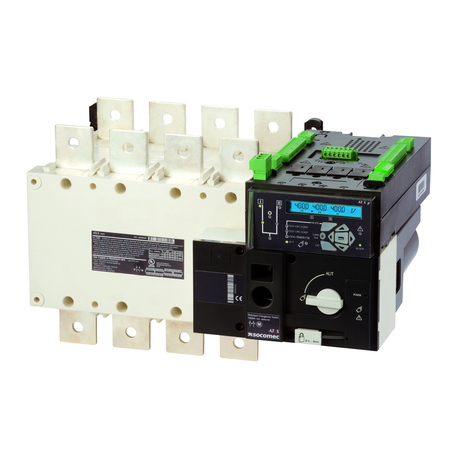
• Ample accessories to suit specific requirements. • Fully integrated ATS controller specifically designed for Mains / Genset Applications. • Power supply continuity for most network (transformer) applications... mains / mains Automatic transfert Switch ATyS t LOAD ATYS t - 541 995 D - SOCOMEC... -
Page 9: The Atys Family Product Range
3. THE ATyS FAMILY PRODUCT RANGE The ATyS t has been engineered by the SOCOMEC centre of excellence in France who boasts it’s very own in-house 100MVA instantaneous power test lab accredited by COFRAC and working in partnership with: KEMA, CEBEC, UL, CSA, ASTA, Lloyd’s Register of Shipping, Bureau Véritas, BBJ-SEP, EZU, GOST-R…... - Page 10 Peak shaving functionality • 4 - 20mA communication module (Optional) • KWh Pulsed output module (Optional) • Counters KWh, permutation… • LCD display for programming, metering, timers and counters • Possibility to add optional functionality ATYS t - 541 995 D - SOCOMEC...
-
Page 11: Quick Start
208-277 VAC ±20%: • ATyS D10 Interface (remote display). 50/60 Hz 50/60 Hz • Voltage sensing kit. • Sealable cover. • RJ45 cable for ATyS D10 => ATyS t ats Voltage sensing ats Voltage sensing For further details refer to the product instruction manual Input Input under chapter "Spares and Accessories"... - Page 12 CONTROL / COMMAND Terminals Example: Control wiring for a 400VAC application having a 3 phase and neutral supply. Sensing Kit Ensure that the product is in Manual Mode. er to ATyS t ccessories for details) 10. O/P to ATyS D10 remote display preferred source 11.
-
Page 13: Quick Start Atys T Frame B3 To B5 (125A To 630A) Continued
PROG OK button momentarily. wiring to the ATyS t voltage sensing terminals 103 – 106 and 203 – 206 has been done. It is preferable to use the ATyS sensing kit that may be provided as an accessory. - Page 14 F 10% 21. Emergency manual operation shaft location Adjustable from 0 to 60 minutes. (Accessible only in manual mode) 22. Switch position indication window: itch I (On switch I) O (Off) II (On switch II). ATYS t - 541 995 D - SOCOMEC...
-
Page 15: Quick Start Atys T Frame B6 To B8 (800A To 3200A)
208-277 VAC ±20%: • ATyS D10 Interface (remote display). 50/60 Hz 50/60 Hz • Voltage sensing kit. • Sealable cover. • RJ45 cable for ATyS D10 => ATyS t ats Voltage sensing ats Voltage sensing For further details refer to the product instruction manual Input Input under chapter "Spares and Accessories"... - Page 16 ATyS t 800 to 1600 A Dimensions stEP 1 51,5 Installation in mm. Caution: Recommended Ensure that the orientation product is installed on a flat rigid surface. Door cut-out for ATyS t 2000 to 3200 A 51.5 front panel. ATyS t 800 to 1000 A...
-
Page 17: Quick Start Atys T Frame B6 To B8 (800A To 3200A) Continued
PROG OK button momentarily. wiring to the ATyS t voltage sensing terminals 103 – 106 and 203 – 206 has been done. It is preferable to use the ATyS sensing kit that may be provided as an accessory. - Page 18 F 10% 21. Emergency manual operation shaft location Adjustable from 0 to 60 minutes. (Accessible only in manual mode) 22. Switch position indication window: itch I (On switch I) O (Off) II (On switch II). ATYS t - 541 995 D - SOCOMEC...
-
Page 19: General Overview
Position order I-O-II Remote control enable Override controls and force to Off position 17. Sliders for Terminal Shields 18. Fixing holes for terminal Shields 19. Emergency manual operation shaft location (Accessible only in manual mode) ATYS t - 541 995 D - SOCOMEC... -
Page 20: Product Identification
10. Dip switch configuration identification. 11. Motor barcode and serial number 12. Emergency manual operation direction of rotation indication 13. Output contacts identification label. 14. Input contacts identification label. 15. Guide to ATyS t programming steps. ATYS t - 541 995 D - SOCOMEC... -
Page 21: Ats Control Module Interface
Yellow steady light when in remote control mode. Remote control mode is achieved with the Auto/Manu selector switched to Auto and terminals 312 closed with terminal 317. Remote control orders are received through closing 314 to 316 with 317. ATYS t - 541 995 D - SOCOMEC... -
Page 22: Environmental
60 °C to 70 °C * Simplified derating method: Ithu ≤ Ith x Kf * A more precise calculation may be done for specific applications. Should this be required please contact SOCOMEC. 5.4.2.2. Hygrometry • 80% humidity without condensation at 55°C •... -
Page 23: Volume And Shipping Weights By Reference Atys T
95 43 4 200 62,7 78,7 730x800x600 95 43 3 250 51,8 67,8 730x800x600 2500A 95 43 4 250 62,7 78,7 730x800x600 95 43 3 320 62,1 78,1 730x800x600 3200A 95 43 4 320 76,4 92,4 730x800x600 ATYS t - 541 995 D - SOCOMEC... -
Page 24: Ce Marking
4KV (B) ESD air 61000-4-2 8KV (B) Electromagnetic field 61000-4-3 10V/m (A) RF Conducted 61000-4-6 10V (A) Burst 61000-4-4 2KV (B) power 1KV (B) control Surge Common 61000-4-5 2KV (B) Surge differential 61000-4-5 1KV (B) ATYS t - 541 995 D - SOCOMEC... -
Page 25: Atys T Accessories Available
RJ 45 communication cable (3m long) for use with the D10 Included as standard for ratings from 2000 to 3200A. For Low remote display/controller or Ethernet modules. level AC: please consult SOCOMEC. KEYLOCKAUTO/MANUALSELECTORSWITCH Others: The ATyS t mode selector switch is delivered with a rotary Refer to the end of this instruction manual or the latest handle as standard. -
Page 26: Installation
210 50 35 35 11 3.5 39.5 133.5 170 140 15 270 65 45 50 13 42.5 37.5 190 260 220 20 270 65 45 50 13 42.5 37.5 190 260 220 20 All dimensions in mm ATYS t - 541 995 D - SOCOMEC... -
Page 27: Dimensions: Frame B6 & B7 (800A To 1600A)
Terminal Body Switchmounting Connection dimensions screens Rating(A) F 3p. F 4p. J 3p. J 4p. M 3p. M 4p. 60.5 47.5 66.5 1000 60.5 47.5 66.5 1250 47.5 66.5 1600 67.5 All dimensions in mm ATYS t - 541 995 D - SOCOMEC... -
Page 28: Dimensions: Frame B8 (2000A To 3200A)
CautIOn (when using the atys t emergency handle: note 2). Overalldimensions Switchmounting Rating(A) A 3p. A 4p. M 3p. M 4p. 2000 … 3200 All dimensions in mm ATYS t - 541 995 D - SOCOMEC... -
Page 29: Mounting Orientation
125A to 630A 800A to 1600A Itispossibletomountthebridgingbarsoneithersideoftheswitch Recommended tightening torque: Maximum tightening torque: M6: 4,5 N.m M6: 5,4 N.m M8: 8,3 N.m M8: 13 N.m M10: 20 N.m M10: 26 N.m M12: 40 N.m M12: 45 N.m ATYS t - 541 995 D - SOCOMEC... -
Page 30: Terminal Shrouds
Frame B3 to Frame B5: • Upstream, downstream, front or rear mounting. • When fitted with bridging bars only the front terminal shrouds are to be installed. 6.3.3. Terminalscreens 125A to 630A 500A to 1600A 2000A to 3200A ATYS t - 541 995 D - SOCOMEC... -
Page 31: Copper Bar Connection Kits (2000A To 3200A : Frame B8)
Note: Reference numbers and quantity given above and below are for one connection and per pole. For a full set multiply the quantity indicated by the number of poles (3 or 4 pole) and then multiply by 2 (N° of switches) ATYS t - 541 995 D - SOCOMEC... -
Page 32: Incoming Copper Bar Connection Kit Assembly
Connection 2900AMax bar 2619 1200 included with 3200A V10 & V11 Kit : 2699 1201 x 2 2629 1200 x 1 4109 0320 x 1 Kit : 2629 1200 x 2 2639 1200 x 2 ATYS t - 541 995 D - SOCOMEC... -
Page 33: Power Supply
1 set including 2 spacers raises the device’s terminals 10mm away from the bottom of the enclosure or frame on which the device is mounted. These may also be used to replace the original mounting spacers. ATYS t - 541 995 D - SOCOMEC... -
Page 34: Padlocking Key Interlocks
91 (fast-on) Pos I Pos II When mounting one auxiliary contact on position I or II, use the short screws provided. When mounting two auxiliary contacts on position I or II, use the long screws provided. ATYS t - 541 995 D - SOCOMEC... -
Page 35: Connections
Cu (mm²), Ith Maximum 2x185 2x300 2x300 4x185 4x185 6x185 cables section Cu (mm Maximum bars width Cu (mm) Note for all ratings: Take into account the connection cable lengths and/or others environmental specific operating conditions. ATYS t - 541 995 D - SOCOMEC... -
Page 36: Connection
Uc 208-277V~ +/-20% 50/60Hz Uc 208-277V~ +/-20% 50/60Hz Uc 208-277V~ +/-20% 50/60Hz omsumption: 22VA Power comsumption: 22VA Power comsumption: 22VA Power comsumption: 22VA e instruction sheet See instruction sheet See instruction sheet See instruction sheet ATYS t - 541 995 D - SOCOMEC... -
Page 37: Networks And Power Connection Possibilities
Source 1 Source 2 Load Load 4BL three phase network with neutral 4NBL three phase network with neutral (with 1 CT connected on Phase 1) Source 1 Source 2 Source 1 Source 2 Load Load ATYS t - 541 995 D - SOCOMEC... -
Page 38: Metering And Sensing Details
U12, U23, U31 U12, U23, U31 U12, U23, U31 Source V1, V2, V3 V1, V2, V3 Source presence (source available) Source in ranges (U, V, F) Rotation phase order Neutral position Voltage unbalanced is lower than threshold ATYS t - 541 995 D - SOCOMEC... -
Page 39: Control Circuits
Verify that the auxiliary power supply feeding terminals 101 and 102 / (201 and CautIOn 202) are within the limits of 208VaC -> 277VaC ±20% do not handle any control or power cables connected to the atys when voltage dangeR may be present. ATYS t - 541 995 D - SOCOMEC... -
Page 40: Atys T Input And Output Contacts
13: 480 / 277 Motorised Changeover Switch PROG 1600A Ref : 95054160 207 208 209 210 Set Dip Set Pot ATyS Ready ! Press Press 60ms Ø 4 ... 8mm PROG PROG ATYS t - 541 995 D - SOCOMEC 207 208 209 210... - Page 41 417 ONLY. Common supply for inputs 1 to 4 (413 - 416) Remote Output to D10 remote display module RJ 45 Up to 3m Interface straight cable *For metering and sensing details, please refer to page 37. ATYS t - 541 995 D - SOCOMEC...
-
Page 42: Voltage Sensing And Power Supply Kit
3 wire kits (those without a neutral) do not include for the power supply to terminals. (101-102 and 201 – 202) Ensure that you have ordered the correct reference prior to installation. (Refer to the accessory section for details). Sources Sources ATYS t - 541 995 D - SOCOMEC... -
Page 43: Sensing Kit Wiring Diagram
800 A kit output cables always on the right hand side (control module side). Kit connection on power switches terminals Red wires Black wires mechanical cables support 202201 Connection on power supply and control module ATYS t - 541 995 D - SOCOMEC... -
Page 44: Network
For network 220/240 VAC ± 20%, power supply conductor (no kit modification required): cables A-B to connect between phases Black wires Red wires Red wires Black wires mechanical mechanical cables cables support L/N N/L support L/N N/L ATYS t - 541 995 D - SOCOMEC... -
Page 45: Atys T Operating Modes
(Refer to product catalogue) Depending on the state of the ATyS t the ATS automation may change the switch WaRnIng position as soon as the mode selector is switched to AUT. This is a normal operation. ATYS t - 541 995 D - SOCOMEC... -
Page 46: Manual Operation
The ATyS t includes a dual power supply and is to be powered between terminals 101 - 102 and 201 – 202 (2 different supplies - main & alternative) within the limits of: 2x 208 – 277VAC ± 20% / (166 – 332VAC) / 50/60Hz ± 10%. ATYS t - 541 995 D - SOCOMEC... -
Page 47: Voltage Sensing Inputs
Dual auxiliary supply: 50/60Hz Uc 208-277V~ +/-20% 50/60Hz Uc 208-277V~ +/-20% 50/60Hz Uc 208-277V~ +/-20% 50/60Hz Uc 208-277V~ +/-20% 50/60Hz ATYS t - 541 995 D - SOCOMEC Power comsumption: 22VA Power comsumption: 22VA Power comsumption: 22VA Power comsumption: 22VA See instruction sheet... -
Page 48: Fixed Inputs
With inhibition active, the ATyS t may be operated in manual mode (with the direct handle) or in remote control mode with contacts 312 – 317 closed. • P in417:Common Common supply for fixed inputs 1 – 4 on terminals 413 to 416. ATYS t - 541 995 D - SOCOMEC... - Page 49 (1st order received is held until no longer maintained). position II maintened • If order I or II disappears, the device returns to zero position. (With the power supply available). (Note : Excludes position switching delays) ATYS t - 541 995 D - SOCOMEC...
-
Page 50: Fixed Outputs - Dry Contacts
(Normally Open contact that is held closed when the ATS is available) The above contacts may be used separately for precise monitoring of the state of each module or wired in series to monitor the availability of the ATS and motorisation modules as a complete unit. ATYS t - 541 995 D - SOCOMEC... -
Page 51: Programming
Programming is carried out in 5 easy steps : Note: Ensure that the ATyS t is in “Manual Mode” with the auxiliary and network supplies available. POWER Motorised Changeover Switch 1600A Ref : 95054160 ATyS Ø 4 ... 8mm ATYS t - 541 995 D - SOCOMEC... -
Page 52: Step 1: Atys T Dip Switches Setting Options
11: 400 / 230 11: 400 / 230 12: 415 / 240 12: 415 / 240 13: 480 / 277 13: 480 / 277 ATYS t - 541 995 D - SOCOMEC Motorised Changeover Switch Motorised Changeover Switch PROG 1600A 1600A Ref : 95054160... -
Page 53: Step 2: Atys T Potentiometer Setting Options
1: 220 / 127 Motorised Changeover Switch 2: 380 / 220 3: 400 / 230 1600A Ref : 95054160 ATYS t - 541 995 D - SOCOMEC 4: 415 / 240 5: 480 / 277 Set Dip Set Pot 6: 208 / 120... -
Page 54: Step 4: Saving The Configured Values
11: 400 / 230 12: 415 / 240 13: 480 / 277 Motorised Changeover Switch PROG 1600A Ref : 95054160 Set Dip Set Pot ATyS Ready ! Press Press 60ms Ø 4 ... 8mm PROG PROG ATYS t - 541 995 D - SOCOMEC... -
Page 55: Characteristics
6.3/ 7.5 6.3/ 7.5 6.3/ 7.5 7.2/ 8.0 7.3/ 8.4 7.3/ 8.4 12.0/ 13.9 12.5/ 14.6 Weight ATyS t, g, p 3 P / 4 P (kg) 6.8/ 8.0 6.8/ 8.0 6.8/ 8.0 7.7/ 8.5 7.8/ 8.9 7.8/ 8.9 12.5/ 14.4 13.0/ 15.1 (1) 3-pole device with 2 „+“... - Page 56 Weight ATyS d 3 P / 4 P (kg) 28.5/ 32.8 29.0/ 33.5 29.5/ 34.2 33.7/ 40.0 51.3/ 62.2 51.3/ 62.2 61.6/ 75.9 Weight ATyS t, g, p 3 P / 4 P (kg) 29.0/ 33.3 29.5/ 34.0 30.0/ 34.7 34.2/ 40.5 51.8/ 62.7 51.8/ 62.7 62.1/ 76.4 (1) 3-pole device with 2 „+“...
-
Page 57: Preventive Maintenance
Good engineering practice is imperative whilst all necessary precautions must be taken to ensure that the intervention (whether directly or indirectly) remains safe in all aspects. ATYS t - 541 995 D - SOCOMEC... -
Page 58: Trouble Shooting Guide
• The FAULT LED will also illuminate when the aux power supply is present but out of range. • Should the Fault LED remain on abnormally, contact SOCOMEC. The fault LED is on • Switch the ATyS t from AUT to Manual and back to AUT. Should the fault condition... -
Page 59: Accessories
50 x 6 4109 3080 4109 4080 800 … 1000 50 x 6 1250 60 x 8 4109 3120 1250 60 x 8 4109 4120 4109 3160 1600 90 x 10 1600 90 x 10 4109 4160 ATYS t - 541 995 D - SOCOMEC... -
Page 60: Copper Bar Connection Kits
9509 0120 1250 1600 9509 0160 12.6. Autotransformer400/230VAC Rating(A) Framesize Reference For applications without neutral, this autotransformer 125 … 3200 B3 … B8 1599 4064 provides the 230 VAC required to power these ATyS products. ATYS t - 541 995 D - SOCOMEC... -
Page 61: Dc Power Supply
For power supply and voltage measurement (4 wire, three-phase) for the note: the 3-pole version does not ATyS t, g and p. integrate the power supply. Routing of the conductors is controlled, which means that no specific protective device is necessary for these connections. -
Page 62: Auxiliary Contacts (Additional)
0 using a RONIS EL11AP position I, 0 or II. lock (factory fitted). Rating(A) Framesize Reference 125 … 630 B3 … B5 9599 1006 800 … 3200 B6 … B8 9599 1004 ATYS t - 541 995 D - SOCOMEC... -
Page 63: Remote Interface
Length Reference RJ45 cable 1599 2009 12.17. Sealablecover use - for atyS t and g Prevents access to the ATyS t and g configuration potentiometers and DIP switches (seals supplied). Rating(A) Framesize Reference 125 … 3200 B3 … B8 9599 0000 12.18.Auto/Manualkeyselector... -
Page 64: Spare Parts
9509 5120 1600 A 9509 5160 9509 5320 2000 ... 3200 A 13.3. Power section References to be used for replacing the switching module of ATyS r, d, t, g or p. Please contact SOCOMEC. ATYS t - 541 995 D - SOCOMEC... -
Page 65: Atys Family: Ordering Information
The following is an ordering guide for ATYS Motorised Transfer Switches delivered inclusive of the emergency handle and storage clip. This guide is intended so as to explain the logic behind SOCOMEC ATYS reference numbers. When ordering please consult the latest SOCOMEC catalogue. - Page 66 ATYS t - 541 995 D - SOCOMEC...
- Page 67 CORPORATE HQ CONTACT: SOCOMEC SAS 1-4 RUE DE WESTHOUSE 67235 BENFELD, FRANCE www.socomec.com 541 995 D - en - 01/17...