
Related Manuals for Hitachi VSP N800


Summary of Contents for Hitachi VSP N800
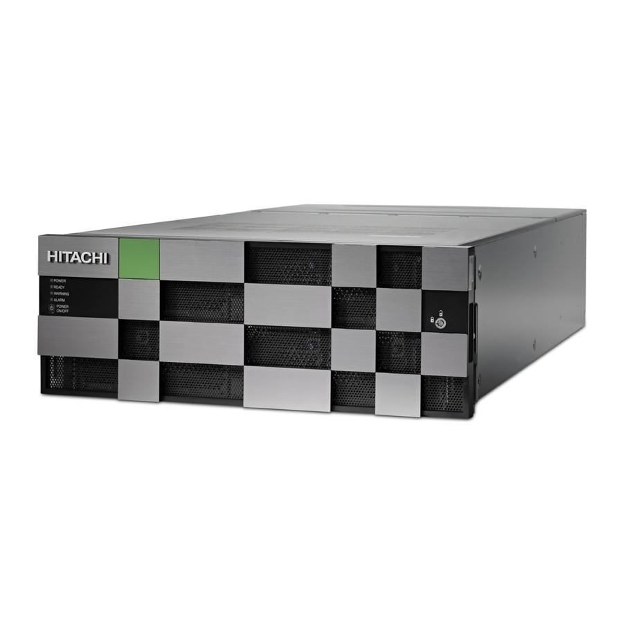
- Page 1 Hitachi Virtual Storage Platform N800 83-06-0x Hardware Reference Guide This document provides information about the system hardware components, mechanical, and environmental specifications for the VSP N800 storage system. MK-94HM8054-02 March 2021...
- Page 2 Hitachi, Ltd., or Hitachi Vantara LLC (collectively “Hitachi”). Licensee may make copies of the Materials provided that any such copy is: (i) created as an essential step in utilization of the Software as licensed and is used in no other manner;...
-
Page 3: Table Of Contents
Changes in this revision..................7 Document conventions..................7 Conventions for storage capacity values............. 9 Accessing product documentation..............10 Getting help......................10 Comments......................10 Chapter 1: Hitachi Virtual Storage Platform N800 hardware overview..11 Block configuration.....................11 Unified configuration..................12 VSP N800 model....................12 Features......................15 Scalability......................15 Examples of supported VSP N800 configurations........16 Maximum number of mounted drive trays............ - Page 4 Chapter 6: Maintaining the storage system..........52 Storing the storage system................52 Powering off the storage system................52 Battery unit......................53 Removing cables....................53 Appendix A: Mechanical specifications for VSP N800 ......55 VSP N800 mechanical specifications..............55 Contents VSP N800 Hardware Reference Guide...
- Page 5 Appendix B: Electrical specifications for VSP N800....... 65 Electrical specifications..................65 Appendix C: Environmental specifications for VSP N800....... 67 Environmental specifications................67 Appendix D: iSCSI standards and specifications........73 iSCSI standards....................73 iSCSI specifications................... 73 Appendix E: Replacement parts............. 78 Battery unit......................78 Appendix F: Data and power cables............
-
Page 6: Preface
Preface This guide describes the hardware features and specifications of the VSP N800 storage system. Intended audience This document is intended for Hitachi Vantara representatives, system administrators, authorized service providers, or customers who install, configure, and operate the VSP N800 storage system. -
Page 7: Product Version
Read the release notes before installing and using this product. They may contain requirements or restrictions that are not fully described in this document or updates or corrections to this document. Release notes are available on Hitachi Vantara Support Connect: https://knowledge.hitachivantara.com/Documents. - Page 8 Calls attention to important or additional information. Provides helpful information, guidelines, or suggestions for performing tasks more effectively. Caution Warns the user of adverse conditions and/or consequences (for example, disruptive operations, data loss, or a system crash). Preface VSP N800 Hardware Reference Guide...
-
Page 9: Conventions For Storage Capacity Values
1 KB 1,024 (2 ) bytes 1 MB 1,024 KB or 1,024 bytes 1 GB 1,024 MB or 1,024 bytes 1 TB 1,024 GB or 1,024 bytes 1 PB 1,024 TB or 1,024 bytes Preface VSP N800 Hardware Reference Guide... -
Page 10: Accessing Product Documentation
Getting help Hitachi Vantara Support Website is the destination for technical support of products and solutions sold by Hitachi Vantara. To contact technical support, log on to the Hitachi Vantara Support Website for contact information: https://support.hitachivantara.com/en_us/contact- us.html. Hitachi Vantara Community is a global online community for Hitachi Vantara customers, partners, independent software vendors, employees, and prospects. -
Page 11: Chapter 1: Hitachi Virtual Storage Platform N800 Hardware Overview
Chapter 1: Hitachi Virtual Storage Platform N800 hardware overview The Hitachi Virtual Storage Platform N800 is a modular, rack-mountable storage system, with various fixed storage capacity configurations of FMD DC2 flash storage devices. To deliver consistent low latency host response times and highest IOP performance across all host connection ports, hard-disk drives are supported in an all-flash configuration. -
Page 12: Unified Configuration
■ VSP N800 model The VSP N800 is a highly reliable storage system that offers high storage capacity with full redundancy to better protect data and manage storage operations. The storage system consists of a 4U enclosure that includes two controllers and two NAS modules. - Page 13 DW-F800- ■ DBLC DW-F800- ■ DBLE (Platinum rated power supply.) DW-F800-DBF 5.25-inch 2U (86.2 mm) ■ DW-F800-DBF 5.25-inch 40 + 2 spares 2U (86.2 mm) ■ Chapter 1: Hitachi Virtual Storage Platform N800 hardware overview VSP N800 Hardware Reference Guide...
- Page 14 2.4 TB DKC-F810I-6R0H9M LFF disk drive 6 TB DKC-F810I-10RH9M LFF disk drive 10 TB Flash module drives The VSP N800 storage system supports the listed flash module drive capacities. Model number Drive type Drive capacity DKC-F810I-7R0FP 7 TB DKC-F810I-14RFP 14 TB Solid-state drives The VSP N800 storage system supports the listed SSD capacities.
-
Page 15: Features
Drive type Drive capacity DKC-F810I-3R8MGM 3.8 TB DKC-F810I-7R6MGM 7.6 TB Features The features described in the table are included with VSP N800 Feature Value Maximum cache memory supported 512 GB Maximum number of spare drives Maximum number of RAID groups... -
Page 16: Examples Of Supported Vsp N800 Configurations
Drive trays of trays of drives CBLH 1152 HDDs or SSDs 576 HDDs or SSDs 576 FMDs (HAF) Dense intermix drive 1440 HDDs or tray SSDs Chapter 1: Hitachi Virtual Storage Platform N800 hardware overview VSP N800 Hardware Reference Guide... -
Page 17: Chapter 2: Virtual Storage Platform N800 Controller
Each controller includes the following internal components such as a processor, dual in-line cache memory modules (DIMMs), cache flash memory (CFM), battery, and fans. The controller has an Ethernet connection for out-of-band management using Hitachi Device Manager - Storage Navigator. If the data path through one controller fails, all drives remain available to data hosts using a redundant data path through the other controller. -
Page 18: Cblh Front Panel Leds (Without Bezel)
LEDs on the front panel to turn off. These LEDs return to the on status after the storage system recovers from the controller replacement. CBLH front panel LEDs (without bezel) The following table describes the definitions of the CBLH controller front panel LEDs. Chapter 2: Virtual Storage Platform N800 controller VSP N800 Hardware Reference Guide... - Page 19 Cache flash memory ALM LED (for cache flash Red: Cache flash memory memory) can be removed. CTL ALM LED Red: Controller can be removed. Chapter 2: Virtual Storage Platform N800 controller VSP N800 Hardware Reference Guide...
-
Page 20: Cblh Rear Panel
Off is normal status for configurations without batteries (for example, BKMF-10 and BKMF-20). CBLH rear panel The following table describes the definitions of the CBLH controller rear panel LEDs. Chapter 2: Virtual Storage Platform N800 controller VSP N800 Hardware Reference Guide... - Page 21 CBLH rear panel Number Item Power supply unit Front end module Back end module LAN blade Rear view (includes NAS modules) Chapter 2: Virtual Storage Platform N800 controller VSP N800 Hardware Reference Guide...
-
Page 22: Cblh Power Supply Unit Leds And Connectors
The controllers are equipped with specific interfaces for connecting, powering, configuring, and managing the storage system. The component LEDs display the operating status of the storage system. Front-end modules Chapter 2: Virtual Storage Platform N800 controller VSP N800 Hardware Reference Guide... -
Page 23: 10-Gbps Iscsi Board Leds And Connectors (Optical)
Red: Small form-factor pluggable can be removed. Blue: Normal link status at 16-Gbps. Green: Normal link status at 4-Gbps or 8-Gbps. Fibre Channel connectors Connect to Fibre Channel cables. Chapter 2: Virtual Storage Platform N800 controller VSP N800 Hardware Reference Guide... -
Page 24: Pcie Module
16-Gbps Fibre Channel ports (left to right) CHB number Port 1 Port 2 CHB-1A CHB-1B CHB-1C CHB-1D CHB-1E CHB-1F CHB-1G CHB-1H CHB-2A CHB-2B CHB-2C CHB-2D CHB-2E CHB-2F CHB-2G CHB-2H PCIe module Chapter 2: Virtual Storage Platform N800 controller VSP N800 Hardware Reference Guide... -
Page 25: Lan Blade Leds And Connectors
Off: PCIe is not linked up (PCIe cable might not be connected). If a PCIe cable is connected, it can be removed safely. LAN blade LEDs and connectors Chapter 2: Virtual Storage Platform N800 controller VSP N800 Hardware Reference Guide... -
Page 26: Back-End Modules
Red: LAN blade can be removed. Uninterruptible power supply (UPS) port Back-end modules Number Item Description STATUS LED Green: Back-end module is in the power-on state. Red: Back-end module can be removed safely. Chapter 2: Virtual Storage Platform N800 controller VSP N800 Hardware Reference Guide... - Page 27 Back-end modules Number Item Description PORT LED Blue: Link status is normal. PATH 0 connector Connect to a drive tray. PATH 1 connector Connects to a drive tray. Chapter 2: Virtual Storage Platform N800 controller VSP N800 Hardware Reference Guide...
-
Page 28: Chapter 3: Drive Trays
2.5 inch (SFF) DBSE DW-F800-DBSE 2U (88.2 mm) 2.5 inch (SFF) SFF with front panel bezel Number Item Description POWER LED Green: Drive tray is powered READY LED Green: Drive tray is operational. Chapter 3: Drive trays VSP N800 Hardware Reference Guide... -
Page 29: Sff Front Panel Without Bezel
Can be turned on or ■ turned off by the maintenance utility. ALM LED Red: Drive stopped due to a failure and can be replaced. ACT LED Green: Normal operation. Chapter 3: Drive trays VSP N800 Hardware Reference Guide... -
Page 30: Sff Rear Panel
ALARM LED Red: ENC can be replaced. PATH (IN) LED Blue: IN side port is linked PATH (IN) connector Connects to a controller or drive tray. Chapter 3: Drive trays VSP N800 Hardware Reference Guide... -
Page 31: Sff And Lff Ac Power Supply Unit Leds And Connectors
The DBS and DBL power supply has a Silver efficiency rating. The DBSE and DBLE power supply has a Platinum efficiency rating. Number Item Description RDY LED Green: Normal operation. ACI IN LED Green: AC input is operating normally. Chapter 3: Drive trays VSP N800 Hardware Reference Guide... -
Page 32: Sff Power Supply Unit Leds And Connectors
The following describes the physical specifications of the large form-factor drive tray. Number of Name Model name Height drive slots Drive type DW-F800-DBLC 2U (88.2 mm) 3.5 inch (LFF) DBLE DW-F800-DBLE 2U (88.2 mm) 3.5 inch (LFF) Chapter 3: Drive trays VSP N800 Hardware Reference Guide... -
Page 33: Lff With Front Panel Bezel
Lock Locks and unlocks the front panel bezel by using the supplied key. LFF front panel without bezel Number Item Description POWER, READY, and Green: Drive tray is powered LOCATE LEDs Chapter 3: Drive trays VSP N800 Hardware Reference Guide... -
Page 34: Lff Rear Panel
The twelve 3.5-inch large form factor drives are positioned horizontally. The slots are organized in the following order: LFF rear panel Number Item Description POWER LED Green: ENC is in the power- on state. Chapter 3: Drive trays VSP N800 Hardware Reference Guide... -
Page 35: Sff And Lff Ac Power Supply Unit Leds And Connectors
LEDs to display its operating status. Note: The DBS and DBL power supply has a Silver efficiency rating. The DBSE and DBLE power supply has a Platinum efficiency rating. Chapter 3: Drive trays VSP N800 Hardware Reference Guide... -
Page 36: Sff Power Supply Unit Leds And Connectors
Green: DC input is operating normally. ALM LED Red: Power supply unit can be replaced. Flash module drive tray (DBF) The following describes the physical specifications of the flash module drive tray. Chapter 3: Drive trays VSP N800 Hardware Reference Guide... -
Page 37: Fmd With Front Panel Bezel
Indicates the location of ■ the chassis. Can be turned on or ■ turned off by the maintenance utility. Lock Locks and unlocks the front panel bezel by using the supplied key. Chapter 3: Drive trays VSP N800 Hardware Reference Guide... -
Page 38: Fmd Front Panel Without Bezel
Note: ACT indicator is only printed on some types of FMDs. POWER, READY, and Green: Drive tray is powered LOCATE LEDs Green: Drive tray is operational. Chapter 3: Drive trays VSP N800 Hardware Reference Guide... -
Page 39: Fmd Rear Panel
POWER LED Green: ENC is in the power- on state. Locate LED Amber: Indicates the location of ■ the chassis. Can be turned on or ■ turned off by the maintenance utility. Chapter 3: Drive trays VSP N800 Hardware Reference Guide... -
Page 40: High-Density Intermix Drive Tray (Db60)
High-density intermix drive tray (DB60) The following describes the physical specifications of the high-density drive tray. Number of Name Model name Height drive slots Drive type DB60 DW-F800- 4U (176 mm) 3.5 inch (LFF) DB60C Chapter 3: Drive trays VSP N800 Hardware Reference Guide... -
Page 41: Dense Intermix Drive Tray With Front Panel Bezel
Indicates the location of ■ the chassis. Can be turned on or ■ turned off by the maintenance utility. Lock Locks and unlocks the front panel bezel by using the supplied key. Chapter 3: Drive trays VSP N800 Hardware Reference Guide... -
Page 42: Dense Intermix Drive Tray Display Leds
Rear of drive tray: 48-59 ■ 36-47 ■ 24-35 ■ 12-23 ■ Front of drive tray: 00-11 ■ Chapter 3: Drive trays VSP N800 Hardware Reference Guide... -
Page 43: Dense Intermix Drive Tray Rear Panel
PATH (IN) LED Blue: IN side port is linked PATH (IN) connector Connects to a controller or drive tray. Console This port is reserved. ALARM LED Red: ENC can be replaced. Chapter 3: Drive trays VSP N800 Hardware Reference Guide... - Page 44 Locate LED Amber: Indicates the location of ■ the chassis. Can be turned on or ■ turned off by the maintenance utility. POWER LED Green: ENC is in the power- on state. Chapter 3: Drive trays VSP N800 Hardware Reference Guide...
-
Page 45: Chapter 4: Host Port Expansion Chassis
Green: Host port expansion is turned on. Amber: PCIe module is turned on. Off: PCIe module is turned off. Safety lock Lock or unlock the front bezel. PCIe switchboard Chapter 4: Host port expansion chassis VSP N800 Hardware Reference Guide... -
Page 46: Host Port Expansion Chassis Fan
Red: PCIe switchboard can be replaced safely. Off: PCIe switchboard is powered off. Host port expansion chassis fan Number Item Description ALM LED Red: Fan failure has occurred. Off: Normal operation. Chapter 4: Host port expansion chassis VSP N800 Hardware Reference Guide... -
Page 47: Pcie Cable Connector
InAct Basic LED Amber: Basic PCIe status changed from link up to link down and cables. Cables can be removed safely. Off: Basic PCIe is normal or not set. Chapter 4: Host port expansion chassis VSP N800 Hardware Reference Guide... -
Page 48: Host Port Expansion Chassis Power Supply
Off: Option PCIe is normal or not set. Host port expansion chassis power supply Number Item Description ALM / RDY LED Red: Host port expansion chassis power supply can be replaced safely. Green: Normal operation. Chapter 4: Host port expansion chassis VSP N800 Hardware Reference Guide... - Page 49 Host port expansion chassis power supply Number Item Description AC IN LED Blue: AC input is normal. Chapter 4: Host port expansion chassis VSP N800 Hardware Reference Guide...
-
Page 50: Chapter 5: Nas Module
The NAS module provides communication ports to support file system protocols in a block- or file-system configuration. NAS Module Ports and LEDs Legend Name Color Description User LAN port This is used with the file level access. Chapter 5: NAS module VSP N800 Hardware Reference Guide... - Page 51 6. Target group 6 Cluster port Reserved for future Status LED Green NAS modules are functioning normally. NAS modules can be removed. Link LED Blue Displays link status. Fail LED A failure has occurred. Chapter 5: NAS module VSP N800 Hardware Reference Guide...
-
Page 52: Chapter 6: Maintaining The Storage System
3. Verify the POWER LED on the front of the storage system changes from green to amber. 4. To stop the power supply, remove the power cables from the power supply units on the controller chassis and drive box. Chapter 6: Maintaining the storage system VSP N800 Hardware Reference Guide... -
Page 53: Battery Unit
Observe the following instructions when removing cables form the storage system. To remove a SAS cable, pull the tab of the SAS cable (1) to release the latch and remove the SAS cable (2). Chapter 6: Maintaining the storage system VSP N800 Hardware Reference Guide... - Page 54 To remove a LAN cable, push the top of the LAN cable connector (1) to release the latch and remove the LAN cable (2). To remove a PCIe cable, pull the tab of the PCIe cable (1) to release the latch and remove the PCIe cable (2). Chapter 6: Maintaining the storage system VSP N800 Hardware Reference Guide...
-
Page 55: Appendix A: Mechanical Specifications For Vsp N800
Appendix A: Mechanical specifications for VSP N800 The storage system mechanical specifications are described for VSP N800. VSP N800 mechanical specifications Controller Quantity Component Description CBLH A 4U controller chassis consisting of controllers, channel boards, disk boards, NAS module, AC or DC power supplies, and batteries with cooling fans. - Page 56 The chassis consists of an ENC and AC-DC power supplies equipped with built-in cooling fans. NAS module Component Description NAS module Component for block and file storage configuration Appendix A: Mechanical specifications for VSP N800 VSP N800 Hardware Reference Guide...
- Page 57 3.5-inch drive (LFF and dense intermix drive 2305.58 GB: 10,000 RPM tray - DB60) 3916.14 GB: 7,200 RPM 5874.22 GB: 7,200 RPM 9790.36 GB: 7,200 RPM Only available for DB60/DB60C dense intermix drive tray. Appendix A: Mechanical specifications for VSP N800 VSP N800 Hardware Reference Guide...
- Page 58 Up to 75.2º F (24º C) 5 years Up to 86º F (30º C) 5 years Up to 93.2º (34º C) 4 years Up to 104º (40º C) 3 years Appendix A: Mechanical specifications for VSP N800 VSP N800 Hardware Reference Guide...
- Page 59 16 Gbps Fibre Channel (optical) 32 Gbps Fibre Channel (optical) 10 Gbps iSCSI (optical) 10 Gbps iSCSI (copper) Maximum number of ports 8 Gbps Fibre Channel (NAS module installed) (optical) Appendix A: Mechanical specifications for VSP N800 VSP N800 Hardware Reference Guide...
- Page 60 16 Gbps Fibre Channel Optical (4-port) 32 Gbps Fibre Channel Optical (4-port) 10 Gbps iSCSI (optical) 10 Gbps iSCSI (copper) 10 Gbps Fibre Channel (optical) Transferred block size 512 bytes Appendix A: Mechanical specifications for VSP N800 VSP N800 Hardware Reference Guide...
- Page 61 3 TB (or 4 TB when using the LDEVs of other storage systems) Maximum volumes/host groups and iSCSI 2048 targets Maximum volumes/parity groups 2048 Shared memory and data assurance Appendix A: Mechanical specifications for VSP N800 VSP N800 Hardware Reference Guide...
- Page 62 18.97 x 40.51 x 6.92 inches (482 x 1,029 x 176 mm) (includes the depth of the cable- management arms) Mass The table lists the values of a maximum configuration when all controllers and drives are mounted. Appendix A: Mechanical specifications for VSP N800 VSP N800 Hardware Reference Guide...
- Page 63 240 slots per path, the drive is blocked. Cache specifications Item Specification Capacity (GB) NAS module Cache Capacity DDR3 DIMM 8GB x 12 [Slot] Appendix A: Mechanical specifications for VSP N800 VSP N800 Hardware Reference Guide...
- Page 64 3 hours every six months. Insulation performance Item Specification Insulation withstand voltage AC 1,500 V (100 mA, 1 min) Insulation resistance DC 500 V, 10 M Ω or more Appendix A: Mechanical specifications for VSP N800 VSP N800 Hardware Reference Guide...
-
Page 65: Appendix B: Electrical Specifications For Vsp N800
3460 or less Steady-state power (VA/W) CBLH: 1600/1560 or less SFF drive tray: 480/460 or less LFF drive tray: 380/350 or less FMD drive tray: 520/490 or less Appendix B: Electrical specifications for VSP N800 VSP N800 Hardware Reference Guide... - Page 66 3. This table shows the power requirement (100 V or 200 V) for the maximum configuration . The actual required power might exceed the value shown in the table when the tolerance is included. Appendix B: Electrical specifications for VSP N800 VSP N800 Hardware Reference Guide...
-
Page 67: Appendix C: Environmental Specifications For Vsp N800
10 or less change rate (°C/h) State Controller FMD drive trays Operating 50°F to 104°F DKC-F710I-1R6FM or DKC-F710I-3R2FM drive is (10°C to 40°C) installed: 50°F to 95°F (10°C to 35°C) Appendix C: Environmental specifications for VSP N800 VSP N800 Hardware Reference Guide... - Page 68 5.0 or less at 5 Hz to 300 Hz (no damage to product) 9.8 (1.0 G) Within 5 seconds (resonance point: 10 Hz or less) Transport (packed) 5.0 or less Appendix C: Environmental specifications for VSP N800 VSP N800 Hardware Reference Guide...
- Page 69 3,000 (Environmental temperature: 10°C to 32°C) (Environmental temperature: 900 (Environmental temperature: 10°C to 40°C) when 10°C to 32°C) DKC-F810I-1R6FN/3R2FN/6R4FN/7R0FP/14RFP drive is installed. (Environmental temperature: 10°C to 40°C) Non-operating -60 to 12,000 Appendix C: Environmental specifications for VSP N800 VSP N800 Hardware Reference Guide...
- Page 70 71 dB (Environmental ting 32°C or less) (Environment temperature 32°C or less) temperature 32°C or less) Non- 55 dB 55 dB 71 dB (Environmental operat temperature 32°C or less) Appendix C: Environmental specifications for VSP N800 VSP N800 Hardware Reference Guide...
- Page 71 3. Acoustic power level (LwA) measured by the ISO 7779 standard is 7.2 B. This value changes from 7.2 B to 8.1 B, according to the ambient temperature, drive configuration, and operating status. Appendix C: Environmental specifications for VSP N800 VSP N800 Hardware Reference Guide...
- Page 72 Hitachi storage systems are designed and manufactured for reliable operation when placed 2 meters from the source of the noise. Hitachi does not test storage systems and hard disk drives for compatibility with fire suppression systems and pneumatic sirens. Hitachi also does not provide recommendations or claim compatibility with any fire suppression systems and pneumatic sirens.
-
Page 73: Appendix D: Iscsi Standards And Specifications
RFC 1231 MIB II ■ RFC 1757 RMON ■ RFC 1901 SNMPv2 ■ iSCSI specifications Item Specification Comments iSCSI target function Supported ® iSCSI target function Supported TrueCopy only Appendix D: iSCSI standards and specifications VSP N800 Hardware Reference Guide... - Page 74 Unique value. Cannot be changed. Maximum transfer unit 1,500, 4,500, 9,000 bytes Jumbo frame, MTU size (MTU) (Ethernet frame) greater than 1500 Link aggregation Not supported Tagged VLAN Supported IPv4 Supported Appendix D: iSCSI standards and specifications VSP N800 Hardware Reference Guide...
- Page 75 IPv6 router is connected to the same network, and then set IPv6 global address automatically. Subnet mask Supported Gateway address Supported DHCP Ping (ICMP ECHO) Supported Transmit, Receive IPsec Appendix D: iSCSI standards and specifications VSP N800 Hardware Reference Guide...
- Page 76 Maximum iSCSI connections 255 per iSCSI port at one time CHAP Supported Authentication: login request is sent properly from host to storage. CHAP is not supported during discovery session. Appendix D: iSCSI standards and specifications VSP N800 Hardware Reference Guide...
- Page 77 Example: iqn.1994-04.jp.co.hitachi:rsd.d7m.t.10020.1b000.tar 4. eui: 64-bit Extended Unique Identifier. The eui consists of a type identifier, "eui," and an ASCII-coded, hexadecimal, EUI-64 identifier. Example: eui.0123456789abcdef Appendix D: iSCSI standards and specifications VSP N800 Hardware Reference Guide...
-
Page 78: Appendix E: Replacement Parts
When replacing the battery, follow the given procedure for disposing a used battery. Replacement period The battery lifetime (intake temperature is 30 degrees C or less.) in the standard environment is as shown below. Appendix E: Replacement parts VSP N800 Hardware Reference Guide... -
Page 79: Appendix F: Data And Power Cables
Fibre Channel and iSCSI cables are used to connect the controllers to a switch or host. Serial-attached SCSI (SAS) cables are used to connect drive trays to controllers and other drive trays. Appendix F: Data and power cables VSP N800 Hardware Reference Guide... - Page 80 Fibre Channel cable length based on cable size and port speed. Cable size Speed Maximum cable length 9 micron 1 Gbps 1 km (3281 ft) 2 Gbps 2 km (6562 ft) 50 micron 2 Gbps 300 m Appendix F: Data and power cables VSP N800 Hardware Reference Guide...
-
Page 81: Fibre Channel Cables
Note: Due to high-speed serial data transfer via Fibre Channel, use high-quality FC cables that comply with the Fibre Channel-PH standard. The following figure shows FC direct connection and FC connection through a switch. Appendix F: Data and power cables VSP N800 Hardware Reference Guide... - Page 82 623.36 ft (190 16 Gbps 114.8 ft (35 m) 328.08 ft (100 410.1 ft (125 m) — 32 Gbps 65.62 ft (20 m) 229.7 ft (70 m) 328.08 ft (100 — Appendix F: Data and power cables VSP N800 Hardware Reference Guide...
- Page 83 Multimode GC50, Wavelength: 125-2SR 850 nm (OMx) LC-LC cable DXLC-2PS- 9/125 μm (longwave) SPC-xxM- Singlemode Wavelength: 10/125-2SR 1300 nm The following figure shows the connector used for optical interfaces. Appendix F: Data and power cables VSP N800 Hardware Reference Guide...
-
Page 84: Iscsi Cables
Cable type Interface name Cable One side Other side LC-LC cable Optical Equivalent to 50, 125 mm LC connector LC connector DXLC-2P- Multimode PC-xxM- Wavelength: GC50, 850 nm 125-2SR (OMx) Appendix F: Data and power cables VSP N800 Hardware Reference Guide... - Page 85 LC connector type ■ Connector type: LC duplex receptacle connector ■ Interval: 6.25 mm flat type, two rows ■ Cable specifications for 10 Gbps iSCSI copper interface Appendix F: Data and power cables VSP N800 Hardware Reference Guide...
-
Page 86: Iscsi Standards
RFC 783 TFTP ■ RFC 791 IP ■ RFC 793 TCP ■ RFC 1157 SNMP v1 ■ RFC 1231 MIB II ■ RFC 1757 RMON ■ RFC 1901 SNMPv2 ■ Appendix F: Data and power cables VSP N800 Hardware Reference Guide... -
Page 87: Iscsi Specifications
Unique value. Cannot be changed. Maximum transfer unit 1,500, 4,500, 9,000 bytes Jumbo frame, MTU size (MTU) (Ethernet frame) greater than 1500 Link aggregation Not supported Tagged VLAN Supported IPv4 Supported Appendix F: Data and power cables VSP N800 Hardware Reference Guide... - Page 88 IPv6 router is connected to the same network, and then set IPv6 global address automatically. Subnet mask Supported Gateway address Supported DHCP Ping (ICMP ECHO) Supported Transmit, Receive IPsec Appendix F: Data and power cables VSP N800 Hardware Reference Guide...
- Page 89 Maximum iSCSI connections 255 per iSCSI port at one time CHAP Supported Authentication: login request is sent properly from host to storage. CHAP is not supported during discovery session. Appendix F: Data and power cables VSP N800 Hardware Reference Guide...
-
Page 90: Managing Cables
Minimum bend radius values Fibre Channel 40 mm (1.73 inch) iSCSI optical 40 mm (1.73 inch) Category 5 Ethernet Four times the outside diameter of the cable 40 mm (1.73 inch) Appendix F: Data and power cables VSP N800 Hardware Reference Guide... - Page 91 Cabling full-width modules When cabling full-width modules, such as NAS modules as shown in the following figure, route the cables horizontally, so that they do not interfere when replacing a module. Appendix F: Data and power cables VSP N800 Hardware Reference Guide...
-
Page 92: Ac Power Cables
Utility AC power standards for connector types and voltage levels vary by country. Hitachi provides a variety of power cables that facilitate using storage systems around the world. Hitachi power cables meet the safety standards for the country for which they are intended. Appendix F: Data and power cables... -
Page 93: Power Cable Assemblies
Power cable assemblies Power cable assemblies For information about racks and power distribution units (PDUs), refer to the Hitachi Universal V2 Rack Reference Guide. Hitachi power cables consist of three parts: Plug: Male connector for insertion into the AC outlet providing power. The physical design ■... -
Page 94: Ac Connections
8. 5-wire (three-phase, earth and neutral). Physical variations (connector size and color) indicate amperage rating. AC connections The following table shows and describes the types of AC connections on your storage system. Appendix F: Data and power cables VSP N800 Hardware Reference Guide... - Page 95 2 NEMA 6-15P 3 IEC 83 CEE 7/7 200V-240V 4 CEE (7) II, IV, VII 3 IEC 83 BS-1363 200V-240V 5 BS 1365 3 IEC 83 AS-3112 200V-240V 6 AS C112 Appendix F: Data and power cables VSP N800 Hardware Reference Guide...
-
Page 96: Power Cable Usage Guidelines
Cable and connector Power cable usage guidelines Hitachi storage systems are intended for rack installation and ship with power cords. Installation and service requirements may require additional cords and cables to be ordered. The type of power cable required by a given installation is determined primarily by the: Type of AC line feed provided by the facility. -
Page 97: Three-Phase Power Considerations For Racks
Cable management Rack installations should be planned for operational efficiency, ease of maintenance, and safety. Hitachi offers the Backend Configuration Utility (BECK), a graphical, cable- management application that can relieve the typical cable congestion created when populating a rack with storage systems and their accessories. -
Page 98: Appendix G: Port Address Mapping
The following addresses are available for setting Fibre Channel ports. Loop ID Loop ID Loop ID Loop ID Loop ID AL-PA (0~29) AL-PA (30~59 AL-PA (60~89) AL-PA (90~119) AL-PA (120~125) Appendix G: Port address mapping VSP N800 Hardware Reference Guide... - Page 99 Port address mapping Loop ID Loop ID Loop ID Loop ID Loop ID AL-PA (0~29) AL-PA (30~59 AL-PA (60~89) AL-PA (90~119) AL-PA (120~125) Appendix G: Port address mapping VSP N800 Hardware Reference Guide...
-
Page 100: Appendix H: Non-Hitachi Racks
PDUs and cable loops. Hitachi Universal V2 Rack rail kits Use rail kits to mount the Hitachi Virtual Storage Platform family storage system in a Hitachi Universal V2 Rack. The following tables list the rail kit information for the specified storage systems. -
Page 101: Hitachi Universal V2 Rack Accessories
2. CGR: Corner guide rail kit A3BF-HK-GL-740-1. Hitachi Universal V2 Rack accessories The following table provides rack accessory information for VSP G series storage systems. Table 2 Accessories for the Hitachi Universal V2 Rack Front door Rear door Side panels... - Page 102 Third-party rack support for DB60 dense intermix drive trays Appendix H: Non-Hitachi racks VSP N800 Hardware Reference Guide...
-
Page 103: Appendix I: Regulatory Compliance
Appendix I: Regulatory compliance This equipment has been tested and certified for compliance with the following standards. Appendix I: Regulatory compliance VSP N800 Hardware Reference Guide... - Page 104 USA and Canada 60950-1:2007 EN60950-1:2006+A1 TUV Germany IEC60950-1:2005+A All CB countries IEC60950-1:2005+A S-Mark Argentina TP TC 004/2011 Russia CNS 14336-1 BSMI Taiwan EN60950-1:2006+A1 CE Radio interference VCCI V-3/2013.04 VCCI Japan voluntary control Appendix I: Regulatory compliance VSP N800 Hardware Reference Guide...
-
Page 105: Appendix J: Environmental Notices
They will dispose of it for you. This nickel-metal hydride battery, which is designated as recycling product by a recycling promotion low, must be recycled. The mark posted on the Cache Backup Battery is a three-arrow mark that indicates a recyclable part. Appendix J: Environmental notices VSP N800 Hardware Reference Guide... -
Page 106: Index
LEDS on dense intermix drive tray block drive chassis LEDs cables power supply AC power drive trays Fibre Channel dense intermix iSCSI flash module managing large form-factor removing maximum number required small form-factor CBLH controller rear panel Index VSP N800 Hardware Reference Guide... - Page 107 Hitachi Virtual Storage Platform N800VSP N800 host host port expansion host port expansion chassis PCIe cable connector LEDs front panel bezel LEDs...
- Page 108 73, mechanical standards standards for iSCSI 73, storage storage system maintenance power off regulatory compliance storing storage system controllers CBLH Index VSP N800 Hardware Reference Guide...
- Page 109 Hitachi Vantara Corporate Headquarters Contact Information 2535 Augustine Drive USA: 1-800-446-0744 Santa Clara, CA 95054 USA Global: 1-858-547-4526 HitachiVantara.com | community.HitachiVantara.com HitachiVantara.com/contact...