
Related Manuals for Samson TROVIS I/O


Summary of Contents for Samson TROVIS I/O
- Page 1 QUICK GUIDE KA 5500-Z EN Translation of original instructions TROVIS I/O Edition August 2020...
- Page 2 This quick guide assists you in mounting and operating the device safely. The instructions in this quick guide are binding for handling SAMSON devices. Î For the safe and proper use of these instructions, read them carefully and keep them for later reference.
-
Page 3: Table Of Contents
Contents Disclaimer of liability ..................4 Safety instructions ..................4 Application ....................5 Installation ....................6 Installation .....................7 Electrical connection ..................10 Indicator .....................12 Technical data .....................14 Disposal ......................15 Certificates ....................16 KA 5500-Z EN... -
Page 4: Disclaimer Of Liability
We do not assume any liability for the accuracy or completeness of this document. Moreover, we do not guarantee that the buyer can use the product for an intended purpose. SAMSON rejects any liability for claims by the buyer, especially claims for compensation including lost profits or any other financial loss, except the damage was caused intentionally or by gross negligence. -
Page 5: Application
After the TROVIS I/O module is switched on, it does not perform any control tasks or issue a control signal until the TROVIS 5578 Controller has sent the operation and configuration set- tings over the device bus. -
Page 6: Installation
DIL switches Two DIL switches are used to set the device bus address of the TROVIS I/O module. A third DIL switch allows the activation of the bus termination for the device bus when the TROVIS I/O module is the last device at the end of the device bus network. -
Page 7: Installation
Installation 4.1 Installation Dimensions in mm (W x H x D): 144 x 98 x 54 The controller consists of the electronics housing and the back panel with the terminals. The device is suitable for panel, wall and rail mounting (see Fig. 2). Panel mounting 1. Undo the two screws (1). 2. Pull apart the electronics housing and the back panel. 3. - Page 8 Rail mounting 1. Fasten the spring-loaded hook (5) at the bottom of the top hat rail (3). 2. Slightly push the TROVIS I/O module upwards and pull the top hook (5) over the top hat rail. 3. Undo the two screws (1).
- Page 9 Installation Panel mounting Wall mounting Rail mounting Fig. 2: Mounting KA 5500-Z EN...
-
Page 10: Electrical Connection
Installation 4.2 Electrical connection DANGER Risk of fatal injury due to electric shock. − For electrical installation, you are required to observe the relevant electrotechnical regula- tions of the country of use as well as the regulations of the local power suppliers. Therefore, such work must be performed by trained and experienced personnel. - Page 11 Installation RS485 BE[ ]-1 SF[ ]-2 / RF[ ] BE[ ]-2 SF[ ]-1 BE[ ]-3 VF[ ] RüF[ ] BE[ ]-4 UP[ ]-1 BA[ ]-1 UP[ ]-2 BA[ ]-2 0...10V / PWM AA[ ]-1 0...10V / PWM AA[ ]-2 BA[ ]-3 RK[ ]- 3-PKT BA[ ]-4 2-PKT...
-
Page 12: Indicator
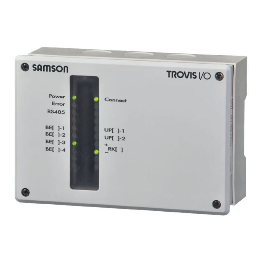
Indicator 5 Indicator Location and meaning The TROVIS I/O module has the following LEDs to indicate various states of the device. The operating states of the device are indicated by LEDs during start-up and servicing. Green: Device functioning properly Red:... - Page 13 One green and one red LED to indicate communication on the interface. The red LED indicates data are being sent by RS485 Blinking the TROVIS I/O module and the green LED indicates that data are being received. Relay contacts (BO) in closed state UP, RK (green)
-
Page 14: Technical Data
Technical data 6 Technical data Inputs 4x Pt 1000, PTC or Ni 1000 sensor inputs, alternatively configurable for binary alarms Outputs 1x three-step signal: rating max. 250 V AC, 2 A alternatively 1x on/off signal: rating max. 250 V AC, 2 A 2x pump output: rating max. 250 V AC, 2 A All outputs are relay outputs with varistor suppression, 2x 0 to 10 V or PWM signal, configurable, to issue a control signal or for pump speed control... -
Page 15: Disposal
Disposal 7 Disposal We are registered with the German national register for waste electric equipment (stiftung ear) as a producer of electrical and electronic equipment, WEEE reg. no.: DE 62194439 Î Observe local, national and international refuse regulations. Î Do not dispose of components, lubricants and hazardous substances together with your other household waste. -
Page 16: Certificates
Certificates 8 Certificates The following certificate is shown on the next page: − EU declaration of conformity The certificate shown was up to date at the time of publishing. The latest certificates can be found on our website: www.samsongroup.com > Products & Applications > Product selector > Automation Systems >... - Page 17 Management par la qualité totale Development Automation and Integration Technologies SAMSON AKTIENGESELLSCHAFT · Weismüllerstraße 3 · D 60314 Frankfurt am Main Revision 08 Fon: +49 69 4009-0 · Fax: +49 69 4009-1507 · E-Mail: [email protected] · Internet: www.samson.de KA 5500-Z EN...
- Page 20 KA 5500-Z EN SAMSON AKTIENGESELLSCHAFT Weismüllerstraße 3 · 60314 Frankfurt am Main, Germany Phone: +49 69 4009-0 · Fax: +49 69 4009-1507 [email protected] · www.samsongroup.com...