GE PACSystems RX3i User Manual
Power sync and measurement system
Hide thumbs
Also See for PACSystems RX3i:
- User manual (169 pages) ,
- Command line interface manual (116 pages) ,
- Application manual (39 pages)

Related Manuals for GE PACSystems RX3i


Summary of Contents for GE PACSystems RX3i
- Page 1 Intelligent Platforms Programmable Control Products PACSystems* RX3i Power Sync and Measurement System User’s Manual, GFK-2749 February 2013...
- Page 2 Features may be described herein which are not present in all hardware and software systems. GE Intelligent Platforms assumes no obligation of notice to holders of this document with respect to changes subsequently made.
- Page 3 Contact Information If you purchased this product through an Authorized Channel Partner, please contact the seller directly. General Contact Information Online technical support and http://support.ge-ip.com GlobalCare Additional information http://www.ge-ip.com/ Solution Provider [email protected] Technical Support If you have technical problems that cannot be resolved with the information in this guide, please contact us by telephone or email, or on the web at http://support.ge-ip.com...
-
Page 5: Table Of Contents
Contents PSM Module Description and Specifications ..............1-1 PSM Module ........................1-2 Terminal Assembly ......................1-3 Connectors ........................1-3 User-Supplied Equipment ......................1-4 PSM Part Numbers ........................1-4 Specifications ..........................1-5 System Operation .......................... 1-7 Autonomous Operation ..................... 1-7 Frequency Measurement ....................1-8 ANSI Functions Supported ...................... - Page 6 Contents Mode Control Bits Sent to PSM module ................. 3-19 Parameters sent to PSM Module ..................3-22 Example Configurations ....................... 3-25 Configuration for 120/240 VAC Single Phase System ........... 3-26 Configuration for 600VAC Single Phase System ............3-29 Configuration for 120/208 WYE Three-Phase Four-Wire System ........3-32 Configuration for 120/208 3-Wire Delta system with Two PTs (Two Wattmeter Method), B-Common ........................
-
Page 7: Psm Module Description And Specifications
Chapter PSM Module Description and Specifications The Power Sync and Measurement (PSM) system monitors two independent three-phase power grids. It incorporates advanced digital signal processor (DSP) technology to continuously process three voltage inputs and four current inputs for each grid. Measurements include RMS voltages, RMS currents, RMS power, frequency, and phase relationship between the phase voltages of both grids. -
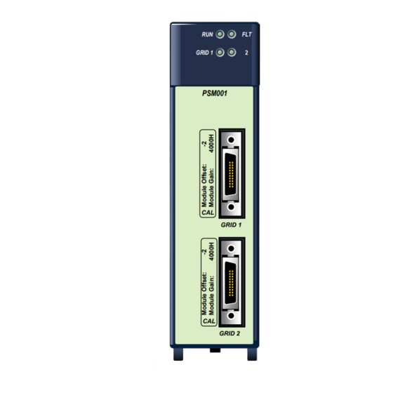
Page 8: Psm Module
PSM Module In addition to configuring the PSM module upon project download from PME, the RX3i CPU can control the PSM module by updating configuration data from the RX3i in the form of %AQ GRID 1 data words and %Q mode control bits during each sweep. The PSM module provides calculated data to the CPU in the form of %AI data words and %I status bits each sweep. -
Page 9: Terminal Assembly
Terminal Assembly The Terminal Assembly accepts three voltage inputs and four current inputs for each of two grids. The Terminal Assembly translates the 0–5 A current signals and the 45–690 VAC RMS voltage signals to low voltage signals for use by the PSM module. Voltage inputs are connected through external, user-supplied potential transformers (PT). -
Page 10: User-Supplied Equipment
User-Supplied Equipment The user must supply the following components depending upon the application. This equipment includes: Current transformers, 5 Amps Potential transformers Fuses (1 Amp each) for each voltage lead connected to the Terminal Assembly. A fuse (1 Amp) for the common or return line for the voltage lead on the Terminal Assembly. -
Page 11: Specifications
Specifications PSM Module Power Requirements Backplane Power Consumption 400 mA max. at 5 VDC Total Power Dissipation 2.0 W max. Isolation from Backplane 1500 VDC Host Controller Compatibility RX3i CPUs For specific versions supported, refer to “Functional Compatibility” in the Important Product Information document, GFK-2748. - Page 12 Terminal Assembly Input Terminal Ratings Current 15 Amps continuous maximum Voltage 690 VAC RMS Sync Relay contacts 150 VAC/VDC at 1 Amp Resistive, maximum Note: Actual contact ratings depend on load type. See “Sync Relay contacts” on page 1-5. RX3i CPU Memory Requirement for Automatic Data Exchange 80 bits 32 bits 64 words...
-
Page 13: System Operation
System Operation The PSM digitizes the voltage and current input waveforms from Grid 1 and Grid 2, storing the results into internal memory buffers. Data is updated every power line cycle. Therefore, the data is updated every 20ms on a 50Hz power grid, or every 16.67ms on a 60Hz power grid. -
Page 14: Frequency Measurement
Frequency Measurement Healthy three-phase power systems produce three almost identical sinusoidal voltage waveforms that swing from positive to negative voltage at a frequency of either 50 or 60 times per second (50–60Hz). The PSM determines the frequency of the power line by looking for the zero crossings, which are places where the voltage crosses zero volts going from positive to negative or from negative to positive. -
Page 15: Ansi Functions Supported
ANSI Functions Supported The Grid 1 and Grid 2 functions are similar, but with differences in implementation. Grid 1 is assumed to be the most stable power source, such a utility. Grid 2 is assumed to be a less stable power source, such as a back-up generator. Either or both grids can be connected for load monitoring, such as motors, lighting, HVAC or server room power. - Page 16 ANSI 59 – Over-voltage Protection This function provides detection of abnormally high phase voltage. It works with phase-to-phase voltage in delta power systems, or phase-to-neutral voltage in wye power systems. Each voltage is monitored separately. An alarm will be triggered if any voltage exceeds the specified OVER_VOLT_THR value, as a percentage of the Nominal Voltage parameter, for a time period longer than OVER_VOLT_DELAY.
-
Page 17: Ansi Functions For Grid 2 (Generator/Generator Grid) Protection
ANSI Functions for GRID 2 (Generator/Generator Grid) Protection Warning It is the responsibility of the user to verify that the system has sufficient frequency stability to maintain the current phase trend during the synchronization process. This requirement is especially true for long breaker delays. Failure to maintain frequency stability during synchronization may result in personal injury, equipment damage, or both. - Page 18 Phase Angle For synchronization, the two grids must be connected when the phase angle difference between the grids is in the range of ±PHASE_SHIFT_THR, and ideally at the point when the two grids are exactly in phase. The phase shift threshold represents an angle window in electrical degrees (usually ±10°) around the 0°...
- Page 19 Slow Rotating Phase Angles In rotating phase angle synchronization, the PSM sets and clears the PhaseShiftOK status bit based on the Angle Delay value. In slowly rotating phase angles where Angle Delay ≤ (Phase_Shift_Thr - 2º)/2, noise-induced jitter in the zero-crossing detection can make the phase angle difference from one power line cycle to the next appear to change direction.
- Page 20 Example: Angle Delay ≤ (Phase_Shift_Thr - 2º)/2 Phase_Shift_Thr = 10º Breaker Delay = 200ms Grid 1 Frequency = 60.00Hz Grid 2 Frequency = 60.01Hz ΔF (slip frequency) = 0.01Hz Angle Delay = (360º x 0.01Hz x 0.200sec) = 0.72º PhaseShiftOK = On @ 0.72º {Angle Delay} PhaseShiftOK = Off @ -2.72º...
- Page 21 Fast Rotating Phase Angles For faster rotating phase angles where Angle Delay > (Phase_Shift_Thr - 2º)/2, these equations apply: PhaseShiftOK = On @ Angle Delay PhaseShiftOK = Off @ Angle Delay – Phase_Shift_Thr -Phase_Shift_Thr +Phase_Shift_Thr 0º 15.9º 25.9º SYNCHROSCOPE Fast Rotation: Angle Delay > (Phase_Shift_Thr - 2º)/2 If a request to sync is on, or received by the PSM module at any time in the green region (while PhaseShiftOK = on), the CloseRelayOK status bit will be set and the IC694ACC200 output contacts will close.
- Page 22 Example: Angle Delay > (Phase_Shift_Thr - 2º)/2 Phase_Shift_Thr = 10º Breaker Delay = 800ms Grid 1 Frequency = 60.00Hz Grid 2 Frequency = 60.09Hz ΔF (slip frequency) = 0.09Hz Angle Delay = (360º x 0.09Hz x 0.800sec) = 25.9º PhaseShiftOK = On @ 25.9º {Angle Delay} PhaseShiftOK = Off @ 15.9º...
- Page 23 ANSI 27 – Under-voltage Protection This function monitors voltages to detect abnormally low grid voltage. It works with phase- to-phase voltage in delta power systems, or phase-to-neutral voltage in wye power systems. Each phase voltage is monitored separately. An alarm will be triggered if any voltage falls below the specified UNDER_VOLT_ THR voltage value for a time period longer than UNDER_VOLT_DELAY.
- Page 24 ANSI 81U – Under-frequency Protection Detection of abnormally low frequency compared to the nominal frequency, to monitor power supply quality. An alarm will be triggered if a circuit’s frequency falls below the nominal frequency minus the UNDER_FRQ_THR for a time period longer than UNDER_FRQ_DELAY.
- Page 25 Installation Chapter General Warnings/Cautions ................2-2 Enclosures ......................2-3 Installing the PSM module .................. 2-3 Installing the Terminal Assembly ................ 2-3 Connector and Cabling information ..............2-4 Wiring ........................ 2-10 GFK-2749...
-
Page 26: Installation
General Warnings/Cautions Warning Installation and wiring procedures must be performed by qualified personnel, as defined below. Qualified personnel are people who, because of their education, experience and instruction and their knowledge of relevant standards, regulations, accident prevention and service conditions, have been authorized by those responsible for the safety of the plant to carry out any required operations and who are able to recognize and avoid any possible dangers. -
Page 27: Enclosures
The PSM module must be installed in a main (CPU) rack in an RX3i system. For system- level installation information, refer to the PACSystems RX3i System Manual, GFK-2314. The IC694PSM001 Module can be hot-swapped in an RX3i backplane. -
Page 28: Connector And Cabling Information
Connector and Cabling Information Basic PSM System Connections Grid 1 power system connections to user PTs with fuses and CTs with shorting bars Sync Contacts Load(s) Interface cables Grid 2 power system connections to user PTs with fuses and CTs with shorting bars PACSystems* RX3i Power System Measurement Module –... -
Page 29: Overview Of Psm System Connection To Public Grid And Generator
Overview of PSM System Connection to Public Grid and Generator GRID 1 (Public Grid) Public Grid Relay Control To Load Sync Relay Control GRID 2 (Generator Grid) Exciter Control Exciter Generator 3-phase AC Generator Primer Mover Control Prime Mover RX3i Controller/ PSM System GFK-2749 Chapter 2 Installation... -
Page 30: Power System Connections
Power System Connections The Grid 1 and Grid 2 terminal blocks connect the Terminal Assembly to the power systems being measured. Each side of the Terminal Assembly has a 12-position terminal block for user connections. The screw terminals accommodate solid or stranded wires from 8 – 18AWG The following table lists the Grid 1 and Grid 2 signal inputs to the Terminal Assembly. - Page 31 PSM Module to Terminal Assembly Connections Two identical 2-meter cables (GEIP part number IC694CBL200) connect the PSM module to the Terminal Assembly. These cables are to be used only for Grid 1 and Grid 2 connections to the IC694PSM001. Warnings The PSM Terminal Assembly connects to hazardous voltages.
- Page 32 Voltage Range Selection The voltage range of each grid can be selected independently. Note that the PSM ConnectionOK status bit is only meaningful when both grids are used with the same voltage range. If different voltage ranges are chosen, the status bit must be ignored and extra attention must be given to correct connections.
-
Page 33: Relay Connector For Sync Contacts
Relay Connector for Sync Contacts The Sync contacts are two redundant, isolated solid-state outputs that signal when it is safe to close the contacts that will parallel Grid 1 to Grid 2. When the PSM module determines that the synchronization parameters have been met, relay contact 1A closes to relay contact 1B, and relay contact 2A closes to relay contact 2B. -
Page 34: Wiring
Wiring Warning HIGH VOLTAGE; HIGH CURRENT DO NOT TOUCH the connectors or wiring after powering up the PSM system. Hazardous voltages exist, and death or injury may result. The Terminal Assembly frame ground connection must always be installed and must be installed before any other wiring is attached. Fuses on the voltage inputs are mandatory. -
Page 35: General Wiring Notes
General Wiring Notes In the following connection diagrams, the line connections are labeled L1, L2, and L3. When you wire the Terminal Assembly into a system, you must decide which line will correspond to which phase. Usually, L1 will correspond to phase A, L2 with phase B, and L3 with phase C. -
Page 36: Wiring Diagrams
Wiring Diagrams Warning Be sure you read and understand all safety-related information in this manual before attempting to wire or use the PSM. Connections for 120/240 VAC system with CTs ..........2-13 Connection to Three-Phase Four-Wire WYE System with Three PTs ..... 2-14 Configuration for Three-Wire Delta system with Two PTs (Two Wattmeter Method) for Load Monitoring ................ -
Page 37: Connections For 120/240 Vac System With Cts
Connections for 120/240 VAC system with CTs The connections shown below detail the installation for a typical North American 120/240 volt AC three-wire single phase connection. The neutral is connected to a ground point, usually at the main power distribution panel. Mandatory equipment includes CT shorting blocks and protection fuses for the voltages. -
Page 38: Connection To Three-Phase Four-Wire Wye System With Three Pts
Connection to Three-Phase Four-Wire WYE System with Three PTs The connections for a typical three-phase, four-wire system are shown below. The PTs are selected to take the nominal line voltage down to the nominal 120VAC, or 600VAC that can be processed by the Terminal Assembly/PSM system. Note that the additional scaling for each CT and PT must be applied to all the results given by the PSM through the host controller. -
Page 39: Configuration For Three-Wire Delta System With Two Pts (Two Wattmeter Method) For Load Monitoring
Configuration for Three-Wire Delta system with Two PTs (Two Wattmeter Method) for Load Monitoring The systems detailed below show two PTs being used in an open delta configuration connected to the Terminal Assembly. The PSM module can be configured for either B phase common, or C phase common. - Page 40 C Phase Common 1A Fuses on secondary Frame Ground CT Shorting Block Frame Ground Load PACSystems* RX3i Power System Measurement Module – February 2013 2-16 GFK-2749...
-
Page 41: Wye Synchro/Power Control Connection
WYE Synchro/Power Control Connection In the following figure the PSM system is connected between two systems, the Public Grid and Generator sub-systems. This connection scheme gives the PSM module all the information needed to make decisions about paralleling the two grids. Fuses on the PT primaries and secondaries are required. -
Page 42: Delta Synchro/Power Monitor Connection (Two Wattmeter Method)
Delta Synchro/Power Monitor Connection (Two Wattmeter Method) This diagram illustrates the wiring of an open delta system utilizing the two wattmeter method of measurement. When used for paralleling the two grids, the missing voltage and current inputs must be configured as unused, so the PSM can reconstruct those signals Fuses on the PT primaries and secondaries are required. -
Page 43: Scaling For Pt And Ct Ratios
Scaling for PT and CT Ratios The IC694PSM001 module reports the voltages and currents measured at the IC694ACC200 terminals. Therefore, the application logic must correct for PT and CT ratios to reflect the actual power grid voltages, currents, powers and energies. Example: Using 480V:120V PTs requires the application logic to multiply the reported voltage values by 4. -
Page 45: Configuration And Data Transfer
Configuration and Data Transfer Chapter The PSM module is configured using the GE Intelligent Platforms programming software. Configuration parameters are used to set nominal values for Grid1 and Grid2 voltage, current and frequency, and to calibrate the PSM system for specific Potential Transformer and Current Transformer gains, increasing the accuracy of the measured values. -
Page 46: Configuration Parameters
Configuration Parameters To configure the PSM module in Proficy Machine Edition under Hardware Configuration, right click and select Add a Module, then select IC694PSM001 from the Specialty Modules tab. PSM001 Settings Parameters Parameter Function Status Input Address Starting address in %I memory for the array of status flags sent from the PSM module to the RX3i CPU. -
Page 47: Grid1 And Grid2 Parameters
Grid1 and Grid2 Parameters The Grid1 tab is used to set the parameters for GRID 1 (Public Grid/Load 1). The Grid 2 tab is used to set the parameters for GRID 2 (Generator Grid/load 2) These parameters include the gain and offset calibration constants required for the module and the gain calibration constant of each of the input channels. - Page 48 Parameter Function Module Offset Calibration constant. Value provided on the PSM001 module label. Setting this value allows maximum measurement accuracy. Range: -1000 to +1000 Default: 0 Module Gain Calibration constant. Value provided on the PSM001 module label. Setting this value allows maximum measurement accuracy. Range: 0h to FFFFh Default: 4000h VAxL Gain...
- Page 49 Parameter Function IBx Gain Calibration constant. Value provided on the ACC200 Terminal Assembly label. Improves the accuracy of the current measurement of channel 4 (IB). This value can be further adjusted to compensate for inaccuracies of external Current Transformers and wiring. Range: 0h to FFFFh Default: 4000h VCxL Gain...
-
Page 50: Ansi Protection Parameters
ANSI Protection Parameters Use this tab to configure the ANSI functions for Grid 1 (Public Grid/Load) and Grid 2 (Generator/Generator Grid). These parameters specify the ANSI alarm thresholds and debounce time periods. Parameter Function ANSI 25 Phase Shift Threshold The angle window, in electrical degrees, around the zero (degrees) degree phase angle difference between Grid 1 and Grid 2 that will be allowed. - Page 51 Parameter Function ANSI 27Under Voltage Delay The amount of time a phase voltage must remain below the (sec) Under Voltage Threshold before the Under Voltage Alarm status is set. Range: 0.1 to 3276.7 Default: 10.0 ANSI 32 Reverse Power Threshold The percentage of nominal power that determines when the Reverse Power Alarm status is set (after the Reverse Power Delay).
- Page 52 Parameter Function ANSI 60 VI Imbalance Threshold The amount any one phase voltage or phase current reading must vary, as a percentage of the average of all three phases within the same grid, to trigger the VI Imbalance alarm (after the VI Balance Delay). The VI Imbalance alarm compares voltage phases to voltage phases, and current phases to current phases within a grid.
-
Page 53: Power Consumption
Power Consumption This tab displays the current that the module consumes for each voltage provided by the power supply. Terminals If Variable Mode is selected in the module Properties, you can use this tab to map I/O variables to the reference memory addresses used by the PSM module. GFK-2749 Chapter 3 Configuration and Data Transfer... -
Page 54: Data Transfer
Data Transfer PSM Status Flags The PSM returns 80 status flag bits to the RX3i controller. Those 80 bits are grouped into five 16-bit words. The first status word (%I1 – %I16) contains the overall PSM status flags. The following two words (%I17 – %I48) contain the individual grid measurement ... - Page 55 Status/Alarm Alarm Timing Availability %I Bit A, B, AB: See Definition Value Offset “Status/Alarm ø ø Timing” on page 3-13 GRID 1 FaultVA 0 = OK 1 = Fault – clamped or not calculated/measured GRID 1 FaultIA ...
- Page 56 Status/Alarm Alarm Timing Availability %I Bit A, B, AB: See Definition Value Offset “Status/Alarm ø ø Timing” on page 3-13 GRID 1 ReversPwrAlarm 0 = OK 1 = ANSI 32 Alarm GRID 1 OverCurrAlarm 0 = OK 1 = ANSI 50 Alarm ...
- Page 57 Status/Alarm Timing Timing A – The PSM buffers an entire power line cycle and takes 11ms to perform calculations on the waveforms. The new status bits are available to the application code after the next PLC input data scan. Total latency = 1-cycle + 11ms + (0 to PLC scan time) Update rate = 1-cycle or the PLC scan rate (whichever is longer) Timing B –...
-
Page 58: Psm Signal Input Data
PSM Signal Input Data The PSM module reports its analog data in 16-bit integer, pseudo-actual values. The integer values are a fixed power of 10 offset from the actual measured value at the Terminal Assembly. The following table lists the units of measure of each type of signal. (For example, voltage is reported in 0.1V units, so a voltage reading of 1256 = 125.6V.) Units of Measure Physical Variable... - Page 59 %AI Word Value Comments Offset GRID 1– Phase B Reactive Power GRID 1– Phase Cn Voltage – RMS value WYE configuration, only (phase-to-neutral) In Delta configuration always 0 WYE and Delta B-common GRID 1– Phase Cp Voltage – RMS value configurations (phase-to-phase) Delta C-common always 0...
- Page 60 %AI Word Value Comments Offset WYE and Delta B-common GRID 2– Phase Cp Voltage – RMS value configurations (phase-to-phase) Delta C-common always 0 GRID 2– Phase C Voltage – DC component WYE and Delta B-common GRID 2– Phase C Current – RMS value configurations Delta C-common always 0 GRID 2–...
- Page 61 Signal Data from the PSM Module for One 3-Wire 1-Phase System If the PSM module is configured as one 3-wire single phase system (600/1200 or 120/240), the data returned to the PLC are as follows: %AI Word Offset Value GRID 1-Section A Voltage – RMS value (phase-to-neutral) GRID 1-Section A Voltage –...
- Page 62 %AI Word Offset Value GRID 2-Total Power Factor GRID 2-Line Frequency GRID 2-Total 15-minute Active Power Demand GRID 2-Total 15-minute Reactive Power Demand GRID 2-Total Active Energy - LSW GRID 2-Total Active Energy - MSW GRID 2-Total Reactive Energy - LSW GRID 2-Total Reactive Energy - MSW Phase Shift between GRID 1 and GRID 2 Voltages FW version / Captured sample / Diagnostic data...
-
Page 63: Data Sent From The Host Controller To The Psm Module
Data Sent from the Host Controller to the PSM Module The RX3i CPU sends 32 %Q bits of Mode Control data and 2 %AQ Parameter words every sweep to the PSM module. Mode Control Bits Sent to PSM module The application logic must apply initial values to these bits on the first RX3i scan. The application can change these settings during operation to modify measurement modes in response to changing conditions. - Page 64 %Q Bit Function Offset GRID 1 Energy reset: When set, the accumulated energy for Grid 1 is reset and held at 0 Wh and 0 VARh. When cleared, the Grid 1 energy value represents the accumulated energy since power-up, or the last reset. Relay open: Works with bit 32 to control the Sync Relay operation.
- Page 65 Reconstructed Variables If a PTn/CTn control bit is set, the corresponding voltage/current is measured and the PSM system can use it. If cleared, the variable is not measured and the PSM module will try to reconstruct the missing samples from the other measured variables. The following table explains which variable in which measured system configuration can be reconstructed.
-
Page 66: Parameters Sent To Psm Module
Parameters sent to PSM Module Many of the configuration parameters can be modified by the application logic during runtime. These parameters are set initially when the hardware configuration is downloaded, but can be modified during runtime to adjust to changing conditions. Parameters are changed using two Word Parameter Write registers in %AQ memory. - Page 67 Index Parameter Value Default value Value Limits (%AQ Word 2) (%AQ Word 1) GRID 2 Nominal Voltage 1200 [0.1 V] 450 to 1500 or 1200 to 7500 GRID 2 Nominal Current 5000 [0.001 A] -7500 to 7500 GRID 2 Nominal Frequency 6000 [0.01 Hz] 5000 or 6000 PHASE_SHIFT_ THR (ANSI 25/1a)
- Page 68 Zero Capture Diagnostic Operation The value written to parameter index 50 selects the variable that will be written to the Diagnostic Data word (%AI offset 60) in the PSM Signal Input Data. The Diagnostic Data word (%AI offset 60) can contain one of the following: ...
-
Page 69: Example Configurations
Example Configurations A portion of the PSM configuration is downloaded with the Proficy Machine Edition hardware configuration (see “Configuration Parameters” on page 3-2). The remaining details must be set, in the form of %Q bits, in application logic when the PLC goes to run mode. -
Page 70: Configuration For 120/240 Vac Single Phase System
Configuration for 120/240 VAC Single Phase System The following shows a typical hardware configuration for a signal phase, 3-wire power monitoring application. This example shows settings for Grid 1; all the settings can be applied to the respective Grid 2 parameters. Note that the offset and gain values were found on the IC694PSM001 module faceplate label and on the IC694ACC200 terminal assembly label. - Page 71 ANSI Protection Tab Note that synchronization is not an option in single phase mode, so the ANSI 25 parameters have no effect and can be left at their default values. GFK-2749 Chapter 3 Configuration and Data Transfer 3-27...
- Page 72 %Q Configuration Values This table shows the settings for Grid 1. The same settings apply to the Grid 2 control bits. These bits must be set during the first PLC scan when the PLC transitions to run mode. %Q offset 2, 3 & 4 and 18, 19 & 20 set the PSM for the field voltage and power configuration.
-
Page 73: Configuration For 600Vac Single Phase System
Configuration for 600VAC Single Phase System The following shows a typical hardware configuration for a signal phase, 3-wire power monitoring application. This example shows settings for Grid 1; all the settings can be applied to the respective Grid 2 parameters. Empirical measurement showed that the system runs, nominally, around 595VAC RMS with a maximum load, after the CT ratio, of 3.7A RMS. - Page 74 ANSI Protection Tab Note that synchronization is not an option in single phase mode, so the ANSI 25 parameters have no effect and can be left at their default values. PACSystems* RX3i Power Sync and Measurement System – February 2013 3-30 GFK-2749...
- Page 75 %Q Configuration Values This table shows the settings for Grid 1. The same settings apply to the Grid 2 control bits. These bits must be set during the first PLC scan when the PLC transitions to run mode. %Q offset 2, 3 & 4 and 18, 19 & 20 set the PSM for the field voltage and power configuration.
-
Page 76: Configuration For 120/208 Wye Three-Phase Four-Wire System
Configuration for 120/208 WYE Three-Phase Four-Wire System The following shows a typical hardware configuration for a 3-phase, 4-wire WYE power monitoring application. This example shows settings for Grid 1; all the settings can be applied to the respective Grid 2 parameters. Note that the offset and gain values were found on the IC694PSM001 module faceplate label and on the IC694ACC200 terminal assembly label. - Page 77 ANSI Protection Tab Note that synchronization is an option in 3-phase mode, so the ANSI 25 parameters can be left at their default values, or changed to suit the application. Since the Breaker Delay is set to the special case value of zero, a static phase angle synchronization is anticipated.
- Page 78 %Q Configuration Values This table shows the settings for Grid 1. The same settings apply to the Grid 2 control bits. These bits must be set during the first PLC scan when the PLC transitions to run mode. %Q offset 2, 3 & 4 and 18, 19 & 20 set the PSM for the field voltage and power configuration.
-
Page 79: Configuration For 120/208 3-Wire Delta System With Two Pts (Two Wattmeter Method), B-Common
Configuration for 120/208 3-Wire Delta system with Two PTs (Two Wattmeter Method), B-Common The following shows a typical hardware configuration for a 3-phase, 3-wire Delta power monitoring application with the B-Phase used as common. This example shows settings for Grid 1; all the settings can be applied to the respective Grid 2 parameters. Note that the offset and gain values were found on the IC694PSM001 module faceplate label and on the IC694ACC200 terminal assembly label. - Page 80 ANSI Protection Tab Note that synchronization is an option in 3-phase mode, so the ANSI 25 parameters can be left at their default values, or changed to suit the application. The Breaker Delay value of 125ms allows the PSM to perform a rotating phase angle synchronization, closing the contacts right at 0º...
- Page 81 %Q Configuration Values This table shows the settings for Grid 1. The same settings apply to the Grid 2 control bits. These bits must be set during the first PLC scan when the PLC transitions to run mode. %Q offset 2, 3 & 4 and 18, 19 & 20 set the PSM for the field voltage and power configuration.
-
Page 82: Configuration For 120/208 3-Wire Delta System With Two Pts (Two Wattmeter Method), C-Common
Configuration for 120/208 3-Wire Delta system with Two PTs (Two Wattmeter Method), C-Common The following shows a typical hardware configuration for a 3-phase, 3-wire Delta power monitoring application with the C-Phase used as common. This example shows settings for Grid 1; all the settings can be applied to the respective Grid 2 parameters. Note that the offset and gain values were found on the IC694PSM001 module faceplate label and on the IC694ACC200 terminal assembly label. - Page 83 ANSI Protection Tab Note that synchronization is an option in 3-phase mode, so the ANSI 25 parameters can be left at their default values, or changed to suit the application. GFK-2749 Chapter 3 Configuration and Data Transfer 3-39...
- Page 84 %Q Configuration Values This table shows the settings for Grid 1. The same settings apply to the Grid 2 control bits. These bits must be set during the first PLC scan when the PLC transitions to run mode. %Q offset 2, 3 & 4 and 18, 19 & 20 set the PSM for the field voltage and power configuration.
-
Page 85: Configuration For 120/208 4-Wire Wye Synchro/Power Control Connection
Configuration for 120/208 4-Wire WYE Synchro/Power Control Connection The following shows a typical hardware configuration for a 3-phase, 4-wire WYE power paralleling/synchronizing application. Note that the offset and gain values were found on the IC694PSM001 module faceplate label and on the IC694ACC200 terminal assembly label. - Page 86 ANSI Protection Tab Note that synchronization is an option in 3-phase mode, so the ANSI 25 parameters can be left at their default values, or changed to suit the application. In this example, the breaker delay has been set to 85ms (the total contact closure time from CloseRelayOK signal to contacts physically closing).
- Page 87 %Q Configuration Values This table shows the settings for both grids. These bits must be set during the first PLC scan when the PLC transitions to run mode. %Q offset 2, 3 & 4 and 18, 19 & 20 set the PSM for the field voltage and power configuration.
-
Page 88: Configuration For 480V 4-Wire Wye Synchro/Power Control Connection
Configuration for 480V 4-Wire WYE Synchro/Power Control Connection The following shows a typical hardware configuration for a 3-phase, 4-wire WYE power paralleling/synchronizing application. The offset and gain values are shown at their default values. For maximum accuracy, the offset and gain values must be set, based on the IC694PSM001 module faceplate label and on the IC694ACC200 terminal assembly label calibration constants. - Page 89 ANSI Protection Tab Note that synchronization is an option in 3-phase mode, so the ANSI 25 parameters can be left at their default values, or changed to suit the application. GFK-2749 Chapter 3 Configuration and Data Transfer 3-45...
- Page 90 %Q Configuration Values This table shows the settings for both grids. These bits must be set during the first PLC scan when the PLC transitions to run mode. %Q offset 2, 3 & 4 and 18, 19 & 20 set the PSM for the field voltage and power configuration.
-
Page 91: Diagnostics
Diagnostics Chapter PSM Module LED Indicators For details on the system status information provided by the LEDs, refer to page 1-2. PSM Module Health Status The %I offset 1 bit is a PSM heartbeat. It toggles every RX3i Controller scan as an indication that the PSM module is communicating with the CPU. -
Page 92: Point Faults
Point Faults Enabling Point Faults on the CPU Memory tab allows the use of Fault and No Fault contacts to alert the PLC logic to an issue with the PSM module. See the PACSystems CPU Reference Manual, GFK-2222 for more details. Point Fault Configuration PACSystems* RX3i Power Transducer Module User’s Manual –... -
Page 93: Fault And No-Fault Contacts
Fault and No-Fault Contacts Fault and No Fault contacts are set to the first %I bit reference address of the module to be monitored. If the Fault bit is set and the No Fault bit is cleared, the CPU is not communicating with the module. -
Page 95: Product Certifications And Installation Guidelines For Conformance
CSA C22.2 No 213-M1987 standard Low Voltage Directive Self-Declaration in accordance with European Directives; Refer to Declaration of Conformity European Safety for Industrial found at http://www.ge-ip.com/ for a complete Control Equipment list of approved products Electromagnetic Compatibility Certification by Competent Body in Directive accordance with European Directives;... -
Page 96: Environmental Specifications
Environmental Specifications Vibration IEC60068-2-6, JISC0911 10 - 57 Hz, 0.006" displacement peak- peak 57 - 500 Hz, 1.0g acceleration IEC60068-2-27, JISC0912 Shock 15G, 11ms 0°C to 60°C: [surrounding air] (32° F to Operating Temperature 140°F) Storage Temperature -40°C to +85°C (-40° F to 185°F) Humidity 5% to 95%, non-condensing EMC Emissions... -
Page 97: Government Regulations
AC power source. The PACSystems RX3i family of products has been tested and found to meet or exceed the requirements of U.S. (47 CFR 15), Canadian (ICES-003), Australian (AS/NZS 3548), and European (EN55011) regulations for Class A digital devices when installed in accordance with the guidelines noted in this manual. - Page 99 Index Enclosure Accuracy requirements, 2-3 measurement, 1-5 Environment Agency approvals, A-1 operating, 1-6 Alarm thresholds, 3-6 Environmental Specifications, A-2 ANSI functions, 1-9 Examples Grid 1, 1-9 configuration, 3-25, See Configuration Grid 2, 1-11 examples ATEX Directive, 1-6, 2-3 imbalance threshold, 3-8 scaling for PT and CT ratios, 2-19 Autonomous operation, 1-7 FCC notice, A-3...
- Page 100 Index notes, 2-11 Wiring diagrams, 2-12 120/240 single phase, 2-13 Parameters delta synchro power monitor, 2-18 Settings, 3-2 three-phase, four-wire with three PTs, 2-14 Parameters (%AQ), 3-22 three-phase, three-wire delta with two PTs, ANSI Protection, 3-6 2-15 GRID1 and GRID2, 3-3 wye synchro power monitor, 2-17 Potential transformers (PTs), 1-3, 2-10 Power requirements...