
Related Manuals for Honeywell LP1501


Summary of Contents for Honeywell LP1501
- Page 1 PW7K1ICE Intelligent Controller LP1501 Installation and Configuration Guide Sep 2020 © 2020Honeywell. All rights reserved. 800-26497...
- Page 2 All other product and brand names are the service marks, trademarks, registered trademarks, or registered service marks of their respective owners. Printed in the United States of America. Honeywell Integrated Security reserves the right to change any information in this document at any time without prior notice.
-
Page 3: Table Of Contents
1.11 FCC Compliance ..................... 18 Chapter 2 PW7K1ICE Wiring and Setup 13 2.1 PW7K1ICE Hardware ..................14 2.2 LP1501 Wiring and Setup Terminal Connections ..........15 2.3 Jumper Configuration ..................16 2.4 DIP Switch Configuration ................. 17 2.5 Factory Default Communication Parameters ............ 17 2.6 Bulk Erase Configuration Memory .............. - Page 4 Device Info Screen .................... 40 Users Screen ...................... 41 Auto Save Screen ....................42 Restore Default Screen ..................42 Load Certificate Screen ..................43 3.4 Initializing the System and Performing a System Download ......44 3.5 Logout ........................ 46 www.honeywell.com...
- Page 5 PW7K1ICE Introduction In this chapter... 1.1 Overview 1.2 General UL-Compliance 1.3 CE + WEEE Marking 1.5 Access Control 1.6 Card Formats: 1.8 Alarm Management 1.9 Warranty 1.10 Liability 1.11 FCC Compliance PW7K1ICE Installation and Configuration Guide, Document 800-26497...
-
Page 6: Overview
1.1 Overview The PW7K1ICE intelligent controller provides decision making, event reporting, and database storage for the Honeywell hardware platform. Two reader interfaces configured as paired or alternate readers provide control for one door. Host communication is via the on-board 10-BaseT/100Base-TX Ethernet port. -
Page 7: General Ul-Compliance
PW7K1ICE Introduction General UL/ULC-Compliance 1.2 General UL/ULC-Compliance A UL-compliant installation requires the following: • The PW7K1ICE panel must be installed within the protected area. • The PW7K1ICE is installed for indoor use only. • The PW7K1ICE must be installed with the provided tamper switch, mounted to the enclosure cover. -
Page 8: Ce + Weee Marking
Description of the used symbol. CE -Standard -Logo. This product complies with the harmonized Regulation of the EU WEEE symbol.It indicates this product is to be recycling and not been thrown in the dustbin Stick the CE label from accessories onto the enclosure www.honeywell.com... -
Page 9: Door Control
PW7K1ICE Introduction Door Control 1.4 Door Control can be controlled using single or paired readers. One (1) physical barrier Two reader ports: Mag, Wiegand, or RS-485 (RS-485 on one reader port capable of supporting two readers.) Two supervised inputs, two relays. Diagnostic LEDs. Dedicated tamper input. -
Page 10: Access Control
• 12 to 32 Access Levels per cardholder (software configurable). • Card Number: 19 digit (64-bit) User Id with 15 digit PIN numbers MAX. • Activation/Deactivation Dates. • Macro capability using IF/(and)/THEN logic. • Anti Passback support • with Nested Area, and Hard, Soft, or Timed Forgiveness. www.honeywell.com... -
Page 11: Card Formats
PW7K1ICE Introduction Card Formats: 1.6 Card Formats: • 8 active card formats per PW7K1ICE. PIV-II, CAC, TWIC card compatible. PW7K1ICE Installation and Configuration Guide, Document 800-26497... -
Page 12: Card Readers
Listed (ALVY) card readers: Manufacturer Model Part Number ProxPro HU/5355AGN00 ProxPro II HU/5455BGN00 ProxPro K HU/5355AGK00 MiniProx HU/5365EGP00 ThinLine II HU/5395CB100 HU/5395CG100 HU/5395CK100 Honeywell OM40 OM40BHONC OM40GHONC OM41 OM41BHONC OM41GHONC OM55 OM55BHONB OM55GHONB OP-10 OP10GENR OP10HONR OP-30 OP30GENR OP30HONR... -
Page 13: Alarm Management
PW7K1ICE Introduction Alarm Management 1.8 Alarm Management • Normally open/Normally closed, unsupervised, supervised. • Standard or custom end-of-line resistances. PW7K1ICE Installation and Configuration Guide, Document 800-26497... -
Page 14: Warranty
PW7K1ICE Introduction Warranty 1.9 Warranty Honeywell Security Access warrants that the product is free from defects in material and workmanship under normal use and service with proper maintenance for one year from the date of factory shipment. Honeywell Security Access assumes no responsibility for products damaged by improper handling or installation. -
Page 15: Liability
This product is not intended for, nor is rated for operation in life-critical control applications. Honeywell Security Access is not liable under any circumstances for loss or damage caused by or partially caused by the misapplication or malfunction of the product. -
Page 16: Fcc Compliance
This device complies with part 15 of the FCC Rules. Operation is subject to the following two conditions: (1) This device may not cause harmful interference, and (2) this device must accept any interference received, including interference that may cause undesired operation. www.honeywell.com... -
Page 17: Pw7K1Ice Hardware
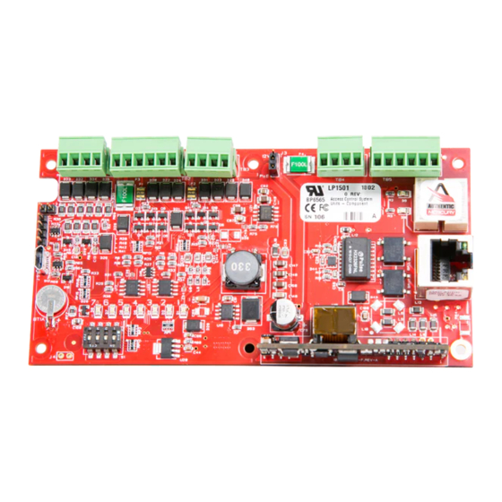
PW7K1ICE Wiring and Setup In this chapter... PW7K1ICE Hardware LP1501 Wiring and Setup Terminal Connections Jumper Configuration DIP Switch Configuration Factory Default Communication Parameters Factory Default Details Input Power Communication Wiring 2.10 Reader Wiring 2.11 Input Circuit Wiring 2.12 Relay Circuit Wiring 2.13... - Page 18 PW7K1ICE Wiring and Setup PW7K1ICE Hardware 2.1 PW7K1ICE Hardware Figure 2-1: PW7K1ICE Control Board www.honeywell.com...
- Page 19 PW7K1ICE Wiring and Setup LP1501 Wiring and Setup Terminal Connections 2.2 LP1501 Wiring and Setup Terminal Connections Table 2-1: PW7K1ICE Terminal Connections Terminal Acronym Description TB1-1 Input 1 TB1-2 TB1-3 Input 2 TB1-4 TB2-1 Reader 1 Power Output - 12VDC...
- Page 20 PW7K1ICE powered from the Ethernet connection PW7K1ICE powered from an external 12VDC power source connected to TB4-3 (VIN), TB4-4 (GND) Factory Use Only Micro USB Port(2.0) 10 Base-T/100Base-Tx Ethernet Connection (Port 0) Cabinet Tamper: normally open switch Micro SD Card www.honeywell.com...
- Page 21 PW7K1ICE Wiring and Setup DIP Switch Configuration 2.4 DIP Switch Configuration The four switches on S1 DIP switch configure the operating mode of the LP1501 processor. DIP switches are read on power up except where noted. read on power- up except where noted...
-
Page 22: Input Power
2. Apply power to the LP1501 board. LED 1 will be on for about 15 seconds while LP1501 boots up. 3. After the LP1501 boots up, watch for LEDs 1 & 2 and 3 & 4 to alternately flash at a 0.5 second rate. -
Page 23: Communication Wiring
• Power is supplied via the Ethernet connection using PoE or PoE+. • Or Local 12VDC power supply, TB4-3 (VIN), TB4-4 (GND). 2.9 Communication Wiring The PW7K1ICE (LP1501) controller communicates to the host via the on-board 10- BaseT/100Base-TX Ethernet interface (port 0). 2.10 Reader Wiring Reader port 1 supports TTL (D1/D0, Clock/Data), F/2F, or 2-wire RS-485 device(s). - Page 24 PW7K1ICE Wiring and Setup Reader Wiring • Inputs on supervised F/2F readers may be unsupervised or supervised shown) Jumper D1 and LED on supervised F/2F readers. Caution: www.honeywell.com...
- Page 25 PW7K1ICE Wiring and Setup Reader Wiring PW7K1ICE Installation and Configuration Guide, Document 800-26497...
-
Page 26: Input Circuit Wiring
Two Form-C contact relays are provided for controlling door lock mechanisms or alarm signaling devices. The relay contacts are rated at 2 A @ 30 VDC, dry contact configuration. Each relay has a Common pole (C), a Normally Open pole (NO) and a www.honeywell.com... -
Page 27: Memory Backup Battery
Door lock mechanisms can generate EMF feedback to the relay circuit that can cause damage and premature failure of the relay plus affect the operation of the LP1501. For this reason, it is recommended that either a diode or MOV (metal oxide varistor) be used to protect the relay. -
Page 28: Status Leds
See Note 1 Cabinet Tamper Reserved for Fault Use Relay K1: ON = Energized Relay K2: ON = Energized Ethernet Speed: OFF = 10 Mb/S, ON = 100 Mb/S OFF = No Link, ON = Good Link, Flashing = Ethernet Activity www.honeywell.com... -
Page 29: Security
0.1 seconds, otherwise, the LED is off. 2.15 IT Security When installing the LP1501, it is important to ensure that it is done in a secure manner. Upon installation, the user accounts to the web configuration page should be created with secure passwords, and that all DIP switches are in the off position for the normal operating mode. - Page 30 • Maximum cable length: 4000' (1,200m) LED Output • TTL compatible • High > 3V • Low < 0.5V • 5mA source/sink maximum Buzzer Output • Open collector • 12VDC open circuit maximum • 40mA sink maximum Cable requirements www.honeywell.com...
- Page 31 PW7K1ICE Wiring and Setup Specifications Power • 1 twisted pair, 18 AWG when using local 12 VDC power supply Ethernet • CAT-5 (minimum) RS-485 • 24AWG, 4,000ft (1,200m) maximum • Twisted pair(s) with an overall shield Alarm Input • 1 twisted pair per input •...
-
Page 32: Additional Mounting Information
2.17 Additional Mounting Information Sources for the optional items are shown below: • 3-gang stainless steel blank cover: Leviton part number 84033-40. Available from Graybar, part number 88158404. • Magnetic switch set: G.R.I. part number: 505. Figure 2-6: Stainless Steel Blank Cover www.honeywell.com... - Page 33 PW7K1ICE Wiring and Setup Additional Mounting Information Figure 2-7: Mounting Plate Dimensions Ø0.16 [Ø4.0] Ø0.16 [Ø4.0] 3-GANG MGT HOLES MR50 MGT HOLES 2.35 [59.7] 3.30 [83.8] 3.63 [92.1] 3.63 [92.1] 3.85 [97.8] 5.50 [139.7] PW7K1ICE Installation and Configuration Guide, Document 800-26497...
- Page 34 PW7K1ICE Wiring and Setup Additional Mounting Information (This page is left blank intentionally for double-sided printing.) www.honeywell.com...
-
Page 35: Chapter 3 Pw7K1Ice System Configuration Via Web Interface
PW7K1ICE System Configuration via Web Interface In this chapter... Overview 3.1.1 Connecting to ACDSM for the First Time Login 3.2.1 Security Certificate Web Server Configuration 3.3.1 Home Screen 3.3.3 Host Communication Screen 3.3.4 Device Info Screen 3.3.5 Users Screen 3.3.6 Auto Save Screen 3.3.7 Restore Default Screen... -
Page 36: Overview
Ethernet cable or by the regular Ethernet cables connected via the hub. 4. Set the host computer to the static IP address 192.168.0.250 to be able to connect to the factory-default PW7K1ICE controller at address 192.168.0.251. 5. Power up the PW7K1ICE controller. www.honeywell.com... -
Page 37: Login
PW7K1ICE System Configuration via Web Interface Login 3.2 Login 1. Launch your web browser. Type the IP address in the browser’s URL field and press Enter. 2. Click the “Click Here to Login” link to display the User Name and Password fields. -
Page 38: Security Certificate
If there is a problem with your security certificate, the system will display the following message: Figure 3-2: Security Certificate Warning Screen If the security certificate of your server is not valid, the system will display the following warning message: Figure 3-3: Security Certificate Invalid Message www.honeywell.com... - Page 39 PW7K1ICE System Configuration via Web Interface Login 1. To download a valid security certificate, click the About Certificate Errors link and display the certificate properties screen: Figure 3-4: Security Certificate Information Screen 2. Click Install Certificate to launch the Certificate Import Wizard: Figure 3-5: Security Certificate Import Wizard PW7K1ICE Installation and Configuration Guide, Document 800-26497...
- Page 40 4. Select “Automatically Select the certificate store based on the type of certificate” option button and click Next to display the completion screen: Figure 3-7: Security Certificate Import Completion Screen 5. Click Finish to display the Login Enabled confirmation message: Figure 3-8: Login Enabled Confirmation Screen www.honeywell.com...
-
Page 41: Web Server Configuration
PW7K1ICE System Configuration via Web Interface Web Server Configuration 6. Click OK to log in to the configuration screen and resume the configuration process. 3.3 Web Server Configuration Complete the login by entering your User Name and Password. 3.3.1 Home Screen The system will display the Home screen which has all the available configuration links on the left navigation bar: Figure 3-9: Configuration Manager Screen... -
Page 42: Network Settings Screen
2. Click the Use Static IP Configuration option button to assign a static IP address, and enter the following information in the appropriate fields: • IP Address • Subnet Mask • Default Gateway 3. Enter the appropriate IP address for the DNS Server field. 4. Click Accept to save the settings. www.honeywell.com... -
Page 43: Host Communication Screen
PW7K1ICE System Configuration via Web Interface Web Server Configuration 3.3.3 Host Communication Screen 1. Click the Host Comm link on the navigation bar to display the Host Communication Settings screen where you can configure the communication port information: Figure 3-11: Host Communication Screen 2. -
Page 44: Device Info Screen
5. Click Accept to save the settings. 3.3.4 Device Info Screen 1. Click the Device Info link on the navigation bar to display the read-only Device Information screen where you can view all the device information: Figure 3-12: Device Information Screen www.honeywell.com... -
Page 45: Users Screen
PW7K1ICE System Configuration via Web Interface Web Server Configuration 3.3.5 Users Screen 1. Click the Users link on the navigation bar to display the Users screen where you can configure all the user-related settings: Figure 3-13: Users Configuration Screen Password Strength Criteria The password strength in the IP Web server can be set to Low, Medium, or High. -
Page 46: Auto Save Screen
4. Click Save Settings. 3.3.7 Restore Default Screen 1. Click the Restore Default link on the navigation bar to display the Restore Default screen where you can restore the default configuration values for the PW7K1ICE settings: www.honeywell.com... -
Page 47: Load Certificate Screen
PW7K1ICE System Configuration via Web Interface Web Server Configuration Figure 3-15: Restore Default Screen 2. Click Restore Default to reload the default factory settings for all the configuration variables. 3. Click Restore Current to reload the current operational settings for all the configuration variables. -
Page 48: Initializing The System And Performing A System Download
1. Right click on the panel and select Download: 2. Clear the Download System check box (see Figure 3-17 on page 49) and select the Initialize check box. 3. Click Download (see Figure 3-17 on page 49). www.honeywell.com... - Page 49 PW7K1ICE System Configuration via Web Interface Initializing the System and Performing a System Download Figure 3-17: Panel Download 4. Right click on the panel again and select Download. This time keep Download System checked and click Download. The panel will be initialized and Pro-Watch will trigger a system download. After you add a PW6K1R1E downstream board to the PW6KICE, you must set the panel's MAC address and IP address (see Figure...
-
Page 50: Logout
PW7K1ICE System Configuration via Web Interface Logout Figure 3-18: Setting MAC address and IP address 3.5 Logout Click Log Out to complete the web server configuration process and log out. www.honeywell.com... - Page 51 (This page is left blank intentionally for double-sided printing.)
- Page 52 For more information: www.honeywellintegrated.com Honeywell Integrated Security 135 W. Forest Hill Avenue Oak Creek, WI 53154 414-766-1700 414-766-1798 Fax European Office Specifications subject to change Boblingerstrasse 17 without notice. D-71101 Schonaich Germany © Honeywell. All rights reserved. 49-7031-637-782 49-7031-637-769 Fax 800-26497 www.honeywell.com...