
Related Manuals for Toshiba APLEX4 Series


Summary of Contents for Toshiba APLEX4 Series
- Page 1 Original Instruction Print & Apply for TOSHIBA Printer B-EX4 APLEX4 SERIES Service Manual 08-03-2017...
- Page 2 Service Manual CE Compliance (for EU only) This product complies with the requirements of EMC, RoHS and Machinery Directives including their amendments. CE marking is the responsibility of the manufacturer : Media Gest Software Logistic S.l., Pasatje de L´Oest, 6c, 08329 Teia (Barcelona), Spain. For a copy of the related CE Declaration of Conformity, please contact your Supplier.
-
Page 3: Product Description
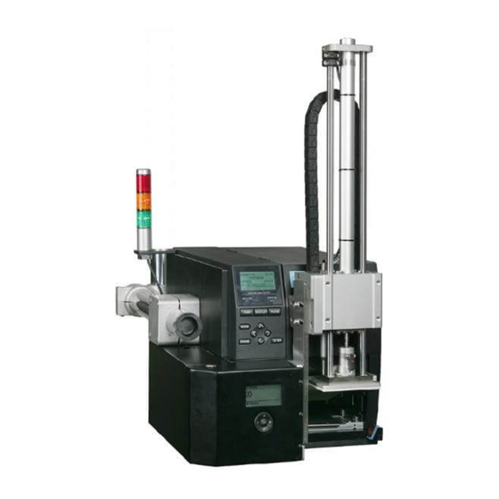
Service Manual Original Instruction Print & Apply for TOSHIBA Printer B-EX4 APLEX4 SERIES Product Description... - Page 4 Service Manual 1.OUTLINE APPEARANCE Front view (with printer) Front view (without printer) Side view (with printer) Side view (without printer)
-
Page 5: Operation Panel
Service Manual OPERATION PANEL Front drawing Test Button Print next label / Clear error LCD screen Normal mode Shows applied label counter Config mode Shows configuration menus/values Selection Button Push Enter configuration menu Rotate left & right Change selection Push Select highlighted value Note: Changes made on configuration menus will be applied just after the modification for testing but will be saved only when EXIT to “Main Menu”. - Page 6 Service Manual Errors APLEX4 communicates with EX4 printer using the I/O I/F on the following way: ISSUE signal is activated The printer starts to print and activates ISSUING signal When ISSUING is deactivated the printer has finished and ERROR signal is read Note: sometimes it is needed to increase ‘Post-Delay’...
- Page 7 Service Manual Original Instruction Print & Apply for TOSHIBA Printer B-EX4 APLEX4 SERIES Maintenance Manual...
- Page 8 Service Manual Piston Piston Monoblock Piston / Guides Piston position sensors Down / Up Sensor (2.2) acts as a position/contact sensor, can be adjusted to increase/decrease contact pressure of the label against the product, moving the sensor up/down ±4mm. The piston has an adjustment to limit the maximum movement (400mm) as a security element to avoid hits on the line o as a waiting point when using blow labeling.
-
Page 9: Control Unit
Service Manual Cables / tubes coming from the control unit are inside the chain which is guided and anchored to the base of the piston onto the same guides forming a compact and factory adjusted unit (11) that allows to work in any position (90-180-270°) with smoothness and accuracy. -
Page 10: Checking Valves
Service Manual Regulators: From left to right: Vaccum, 'Air-assist', Piston down, Piston up. The blow is regulated by time (parameter on the menu). Air outputs are located such that the air outlet is carried out to the outside, preventing any dirt may reach the inside of the control unit. - Page 11 Service Manual Connection board schema CPU – Screen/Keyboard Screen Serial connector to the CPU with power and data. It has its own controller, only receives data from the CPU using an special protocol, in the future can be replaced by other type (i.e.
- Page 12 Service Manual Cable protector Protects the cables and air tubes from control unit to piston. Test button connector To connect the test button located on the control unit cover (10). Control unit cover Protects the control unit. Uses 6 screws (8), contains the screen window and the keyboard window and the...
-
Page 13: Back Panel Connectors
Service Manual General Air Controller Gauge of general air inlet, to the unit. Regulator / stabilizer 4-6 Bars of the air inlet to the unit, filter water and impurities, with output at the end, with indicator pressure and open/close valve. Delivered with inlet ØExt. - Page 14 Service Manual Notes: There is a PTC limitation on power output. Once it is triggered needs some minutes to work again. Input circuit: Activation (ON state) is made connecting INP signal to GND using a contact or a NPN signal from a photocell, inductive sensor, etc. In this state max current is 5mA.
- Page 15 Service Manual CN3 connector (bottom left). Light indicator. Pin Name Description Power 24V GREEN light (Always ON) ORANGE light (IN OPERATION) RED light (ERROR) Notes: It is possible to use these signals to check APLEX status but always respecting the maximum voltage and current values.
- Page 16 Service Manual CN4 connector (bottom right). I/O signals (optional). Pin Name Description OUT1 Pin1 and Pin2 are a free-voltage contact when the OUT1 is ON OUT1 OUT2 Pin3 and Pin4 are a free-voltage contact when the OUT2 is ON OUT2 Power 24V (external) 0V ground (external) Notes:...