
Related Manuals for Honeywell NOTIFIER NFW-50X


Summary of Contents for Honeywell NOTIFIER NFW-50X
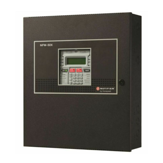
- Page 1 Addressable Fire Alarm Control Panel NFW-50X Manual Document LS10129-001NF-E Rev: C 7/25/2018 ECN: 18-323...
- Page 2 Fire Alarm & Emergency Communication System Limitations While a life safety system may lower insurance rates, it is not a substitute for life and property insurance! An automatic fire alarm system—typically made up of smoke Heat detectors do not sense particles of combustion and alarm detectors, heat detectors, manual pull stations, audible warning only when heat on their sensors increases at a predetermined rate devices, and a fire alarm control panel (FACP) with remote notifica-...
-
Page 3: Installation Precautions
HARSH™, NIS™, and NOTI•FIRE•NET™ are all trademarks; and Acclimate® Plus™, eVance®, FlashScan®, FAAST Fire Alarm Aspiration Sensing Technology®, Honeywell®, Intelligent FAAST®, NOTIFIER®, ONYX®, ONYXWorks®, SWIFT®, VeriFire®, and VIEW® are all registered trademarks of Honeywell International Inc. Microsoft® and Windows® are registered trademarks of the Microsoft Corporation. Chrome™ and Google™ are trademarks of Google Inc. Firefox® is a registered trademark of The Mozilla Foundation. -
Page 4: Section 4: Operating Instructions
Section 4: Operating Instructions 4.1 Panel Control Buttons 4.1.1 Acknowledge The first press of the Acknowledge key silences the piezo sounder, changes flashing LEDs to steady, and also changes the status field on the LCD display from capital letters to small letters. When the piezo is silenced, an acknowledge message is sent to the printer and the history file. -
Page 5: Normal Operation
Normal Operation Operating Instructions Disabled This is a yellow LED that flashes to indicate that a zone, NAC, detector or module has been temporarily disabled in programming by the user. Maintenance This is a yellow LED that flashes to indicate that a smoke detector requires cleaning or replacement due to an invalid chamber reading or excessive drift. -
Page 6: Alarm Operation
Operating Instructions Alarm Operation ; refers to the user programmed noun descriptor from library list resident in the control panel or custom entry via PC. • Third line in display: INVREP indicates an invalid reply from the addressable device. Other possible troubles include: –... -
Page 7: Co Alarm Operation
CO Alarm Operation Operating Instructions • Third line in display: Z000 indicates the zone programmed to this device which, in this example, is general alarm Zone 000. Note that a single device can be programmed to five different zones but only the first zone will be displayed. •... -
Page 8: Process Monitor Operation
Operating Instructions Process Monitor Operation A typical Supervisory event would be displayed as illustrated in the following: ACTIVE SUPERVISORYZ000 10:00A 012116 1M001 Note that, like alarms, supervisory signals latch (except when programmed for supervisory autoresettable) and can be assigned to soft- ware zones. - Page 9 NAC Operation Operating Instructions • Timers are not started • Store event in history buffer • Activate appropriate LED on the N-ANN-LED annunciator (required for this application) • Each N-ANN-LED can support up to 10 zones. Medical alert conditions latch. They can be assigned to software zones. 4.11 NAC Operation There are two programmable NACs (Notification Appliance Circuits) resident on the NFW-50X main circuit board.
-
Page 10: Coded Operation
Operating Instructions Coded Operation Important: When a Notification Appliance Circuit with a mix of audible and visual devices is programmed for silenceable and the syn- chronization feature is selected, only the audible devices will be turned off if the Silence key is pressed. The visual devices (strobes, etc.) will continue to operate. -
Page 11: Special System Timers
Special System Timers Operating Instructions 4.21 Special System Timers 4.21.1 Silence Inhibit Timer This option, if selected, prevents the Alarm Silence key from functioning for 5 minutes following an alarm. A new alarm during the ini- tial 5 minute period will not cause the timer to restart with a new 5 minutes. Silence Inhibit operation requires the approval of the local Authority Having Jurisdiction. - Page 12 Operating Instructions Read Status Alarm/Shorted Condition When in audible Walktest, the panel responds to each new alarm and activates its programmed control outputs for four seconds, if those outputs have been programmed for silenceable activation. It also stores each alarm in the walktest history file which can be sent to an optional printer.
- Page 13 Read Status Operating Instructions Entering the three digit detector address will cause the control panel to display the current status of the selected device. For example, if a detector with address 001 on the SLC loop is entered, a display similar to the following will appear: NORMAL SMOKE(PHOTO) NORTH CLASSROOM Z005...
- Page 14 Operating Instructions Read Status 4.23.4 Timers Pressing 2 while viewing Read Status Screen #2 will cause the following Timer screens to be displayed: TIMERS TIMERS PAS DELAY AC LOSS DELAY PRE SIGNAL CON MOD DLY WATERFLOW These screens will indicate the delay time, in seconds, for each of the first three and last possible delay options. The AC Loss Delay time is displayed in hours.
- Page 15 Read Status Operating Instructions The operator can view all events which have been stored in the history file, only alarms or other events, such as troubles or supervisories, by pressing the corresponding number key. 4.23.9 Annunciators Pressing 1 while viewing Read Status Screen #4 will display the following screens: READ STATUS 1=ANNUNCIATORS ANN-BUS SELECT...
- Page 16 Operating Instructions Read Status Pressing 3 for IP Settings while viewing Communicator Screen #1 will display settings for the ethernet por- READ STATUS INSTALLED tion of the Communicator. The screen will indicate if DHCP has been enabled Yes or disabled No. If the 2=POTS SETTINGS DHCP has not been enabled, the Static Settings will be displayed.
- Page 17 Read Status Operating Instructions DEVICE # DEVICE TYPE % DRIFT COMP CHAMBER TIME/DATE 1D009 SMOKE (PHOTO) 1310 12:02 AM 01-08-2016 Chamber Value The Chamber value should be within the indicated range for the following smoke detectors: • NP-100(R), NP-200(R), FSP-851(T/R), FSP-951(T/R), ND-100(R), and FSD-751(R)PL Addressable Photoelectric Smoke Detectors: 405 - 2100 (obscuration of 1.00%/ft to 3.66%/ft.) •...
- Page 18 Operating Instructions Read Status 4.23.12 Time-Date The operator can view the daylight savings time and the month and week when daylight savings time will READ STATUS 1=FUTURE USE begin and end. Pressing 2 while viewing Read Status Screen #5 will display the following screens: 2=PRINT DAYLIGHT SAVINGS 3=TIME/DATE...
- Page 19 NFW-50X Fire Alarm Control Panel Operating Instructions NORMAL - Only AC POWER is illuminated green. PANEL KEY - The key to open the panel can be found at the following All other indicators are off. LCD display will read SYSTEM ALL location: NORMAL.