
Related Manuals for GE Vivid i n


Summary of Contents for GE Vivid i n
- Page 1 P R E L I M I N A R Y 8.JUL.2009 GEHC_FRNT_CVR.FM GE Healthcare Vivid i n Service Manual Operating Documentation Part Number: FL091021 Revision: 5...
- Page 3 • VERSUCHEN SIE NICHT, DAS GERÄT ZU REPARIEREN, BEVOR DIESES WARNUNG KUNDENDIENST-HANDBUCH NICHT ZU RATE GEZOGEN UND VERSTANDEN (DE) WURDE. • WIRD DIESE WARNUNG NICHT BEACHTET, SO KANN ES ZU VERLETZUNGEN DES KUNDENDIENSTTECHNIKERS, DES BEDIENERS ODER DES PATIENTEN DURCH ELEKTRISCHE SCHLÄGE, MECHANISCHE ODER SONSTIGE GEFAHREN KOMMEN.
- Page 4 GE H EALTHCARE FL091021, R IRECTION EVISION IVID I N ERVICE ANUAL • ESTE MANUAL DE SERVICIO SÓLO EXISTE EN INGLÉS. • SI ALGÚN PROVEEDOR DE SERVICIOS AJENO A GEHC SOLICITA UN IDIOMA QUE NO SEA EL INGLÉS, ES RESPONSABILIDAD DEL CLIENTE OFRECER UN SERVICIO DE TRADUCCIÓN.
- Page 5 ΣΤΟΝ ΑΣΘΕΝΗ ΑΠΟ ΗΛΕΚΤΡΟΠΛΗΞΙΑ, ΜΗΧΑΝΙΚΟΥΣ Ή ΑΛΛΟΥΣ ΚΙΝΔΥΝΟΥΣ. • EZEN KARBANTARTÁSI KÉZIKÖNYV KIZÁRÓLAG ANGOL NYELVEN ÉRHETŐ • HA A VEVŐ SZOLGÁLTATÓJA ANGOLTÓL ELTÉRŐ NYELVRE TART IGÉNYT, AKKOR A VEVŐ FELELŐSSÉGE A FORDÍTÁS ELKÉSZÍTTETÉSE. • NE PRÓBÁLJA ELKEZDENI HASZNÁLNI A BERENDEZÉST, AMÍG A FIGYELMEZTETÉS (HU) KARBANTARTÁSI KÉZIKÖNYVBEN LEÍRTAKAT NEM ÉRTELMEZTÉK.
- Page 6 GE H EALTHCARE FL091021, R IRECTION EVISION IVID I N ERVICE ANUAL • TENTO SERVISNÍ NÁVOD EXISTUJE POUZE V ANGLICKÉM JAZYCE. • V PŘÍPADĚ, ŽE POSKYTOVATEL SLUŽEB ZÁKAZNÍKŮM POTŘEBUJE NÁVOD V JINÉM JAZYCE, JE ZAJIŠTĚNÍ PŘEKLADU DO ODPOVÍDAJÍCÍHO JAZYKA ÚKOLEM ZÁKAZNÍKA.
- Page 7 GE H EALTHCARE FL091021, R IRECTION EVISION IVID I N ERVICE ANUAL • ŠIS EKSPLOATAVIMO VADOVAS YRA IŠLEISTAS TIK ANGLŲ KALBA. • JEI KLIENTO PASLAUGŲ TEIKĖJUI REIKIA VADOVO KITA KALBA – NE ANGLŲ, VERTIMU PASIRŪPINTI TURI KLIENTAS. • NEMĖGINKITE ATLIKTI ĮRANGOS TECHNINĖS PRIEŽIŪROS DARBŲ, NEBENT ĮSPĖJIMAS...
- Page 8 GE H EALTHCARE FL091021, R IRECTION EVISION IVID I N ERVICE ANUAL • ДАННОЕ РУКОВОДСТВО ПО ОБСЛУЖИВАНИЮ ПРЕДОСТАВЛЯЕТСЯ ТОЛЬКО НА АНГЛИЙСКОМ ЯЗЫКЕ. • ЕСЛИ СЕРВИСНОМУ ПЕРСОНАЛУ КЛИЕНТА НЕОБХОДИМО РУКОВОДСТВО НЕ НА АНГЛИЙСКОМ ЯЗЫКЕ, КЛИЕНТУ СЛЕДУЕТ САМОСТОЯТЕЛЬНО ОБЕСПЕЧИТЬ ПЕРЕВОД. • ПЕРЕД ОБСЛУЖИВАНИЕМ ОБОРУДОВАНИЯ ОБЯЗАТЕЛЬНО ОБРАТИТЕСЬ...
- Page 9 GE H EALTHCARE FL091021, R IRECTION EVISION IVID I N ERVICE ANUAL (JA) (ZH-CN) (KO) -vii...
- Page 10 GE Healthcare personnel. In performing all electrical work on these products, GE will use its own specially trained field engineers. All of GE’s electrical work on these products will comply with the requirements of the applicable electrical codes.
- Page 11 The contents of this publication may not be copied or duplicated in any form, in whole or in part, without prior written permission of GE Healthcare. GE Healthcare may revise this publication from time to time without written notice. TRADEMARKS All products and their name brands are trademarks of their respective holders.
- Page 12 GE H EALTHCARE FL091021, R IRECTION EVISION IVID I N ERVICE ANUAL Revision History Revision Date Reason for change MAY 2005 Initial Release. NOV 2005 Revised Spare Parts List update FEB. 2006 Added new cart and transportation Box JAN. 2007...
- Page 13 Vivid i n Models Covered in this Manual ......
- Page 14 GE H EALTHCARE FL091021, R 4+10JUN09 DRAFT IRECTION EVISION IVID I N ERVICE ANUAL CHAPTER 2 Site Preparations Overview ............. 2 - 1 Purpose of Chapter 2 .
- Page 15 Vivid i n Configuration ........
- Page 16 GE H EALTHCARE FL091021, R 4+10JUN09 DRAFT IRECTION EVISION IVID I N ERVICE ANUAL Configuring Peripherals ......... . 3 - 58 Software Options Configuration .
- Page 17 GE H EALTHCARE FL091021, R 4+10JUN09 DRAFT IRECTION EVISION IVID I N ERVICE ANUAL CHAPTER 4 General Procedures and Functional Checks Overview............. .4 - 1 Purpose of Chapter 4 .
- Page 18 Vivid i n Systems - Block Diagram ........
- Page 19 GE H EALTHCARE FL091021, R 4+10JUN09 DRAFT IRECTION EVISION IVID I N ERVICE ANUAL ECG Module ............5 - 38 Overview .
- Page 20 GE H EALTHCARE FL091021, R 4+10JUN09 DRAFT IRECTION EVISION IVID I N ERVICE ANUAL CHAPTER 6 Service Adjustments Overview ............. 6 - 1 Purpose of Chapter 6 .
- Page 21 GE H EALTHCARE FL091021, R 4+10JUN09 DRAFT IRECTION EVISION IVID I N ERVICE ANUAL CHAPTER 7 Diagnostics/Troubleshooting Overview............. .7 - 1 Purpose of Chapter .
- Page 22 Software Installation/Upgrade Procedure Overview ....8 - 56 Vivid i n Software Re-Installation/Upgrade ......8 - 62 Setting the BIOS .
- Page 23 GE H EALTHCARE FL091021, R 4+10JUN09 DRAFT IRECTION EVISION IVID I N ERVICE ANUAL Connecting and Removing Peripherals ......8 - 100 Modo Cart Components Replacement .
- Page 24 Vivid i n Spare Part Kits ........
- Page 25 GE H EALTHCARE FL091021, R 4+10JUN09 DRAFT IRECTION EVISION IVID I N ERVICE ANUAL CHAPTER 10 Care and Maintenance Overview.............10 - 1 Periodic Maintenance Inspections .
- Page 26 Vivid i n Inspection Certificates ........
- Page 27 Overview 1-1-1 Purpose of Chapter 1 This chapter describes important issues related to safely servicing the Vivid i n portable ultrasound scanner. The service provider must read and understand all the information presented here before installing or servicing a unit.
- Page 28 Provides disassembly and reassembly procedures for all Field Replaceable Units (FRUs). • Chapter 9 - Renewal Parts Contains a complete list of field replaceable parts for the Vivid i n portable ultrasound scanner. • Chapter 10 - Care and Maintenance Provides periodic maintenance procedures for the Vivid i n portable ultrasound scanner.
- Page 29 The Vivid i n portable ultrasound scanner is based on parallel products in the Vivid™ family. Using the same advanced technology, the innovative features and versatility of the system represent the future of ultrasound scanning.
- Page 30 Important Conventions 1-2-1 Conventions Used in this Manual 1-2-1-1 Model Designations This manual covers the Vivid i n ultrasound units listed in Table 1-2 on page 1-2. 1-2-1-2 Icons Pictures, or icons, are used wherever they will reinforce the printed message. The icons, labels and conventions used on the product and in the service information are described in this chapter.
- Page 31 GE H EALTHCARE FL091021, R IRECTION EVISION IVID I N ERVICE ANUAL 1-2-1-4 Standard Hazard Icons Important information will always be preceded by the exclamation point contained within a triangle, as seen throughout this chapter. In addition to text, several different graphical icons (symbols) may be used to make you aware of specific types of hazards that could cause harm.
- Page 32 Servicing should be performed by authorized personnel only. Only personnel who have participated in Vivid i n training are authorized to service the equipment. Local laws may restrict this device for sale or use by or on the order of a physician.
- Page 33 Do not let the system strike walls or door frames. • Whenever the Vivid i n scanner is mounted on the Cart and being moved on inclines, make sure that the scanner and all peripherals are securely mounted on the Cart before attempting to move it.
- Page 34 1-3-4-1 Probes All the probes for the Vivid i n ultrasound unit are designed and manufactured to provide trouble-free, reliable service. To ensure this, correct handling of probes is important and the following points should be noted: •...
- Page 35 GE H EALTHCARE FL091021, R IRECTION EVISION IVID I N ERVICE ANUAL 1-3-5 Dangerous Procedure Warnings Warnings, such as the warnings below, precede potentially dangerous procedures throughout this manual. Instructions contained in the warnings must be followed. DANGEROUS VOLTAGES, CAPABLE OF CAUSING DEATH, ARE PRESENT IN THIS EQUIPMENT.
- Page 36 ERVICE ANUAL Section 1-4 Product Labels and Icons The Vivid i n portable ultrasound scanner comes equipped with product labels and icons. These labels and icons represent pertinent information regarding the operation of the unit. 1-4-1 Product Label Locations The following diagrams show the label and icons found on the Vivid i nultrasound unit. All the labels and icons are described in Table 1-5 "Product Icons Vivid i n"...
- Page 37 ANUAL 1-4-2 Label Descriptions The following table shows the labels and symbols that may be found on the Vivid i n ultrasound unit, and provides a description of each label’s purpose and location. Table 1-5 Product Icons Vivid i n...
- Page 38 FL091021, R IRECTION EVISION IVID I N ERVICE ANUAL Table 1-5 Product Icons Vivid i n Label Name Description Location Equipment Type CF IEC 60601-1 indicates equipment having a floating applied part that Above the ECG inlet, ECG connector provides a degree of protection suitable for direct and surgical probes.
- Page 39 Vivid i n Battery Safety NOTE: The Vivid i n portable ultrasound scanner is supplied with a dummy battery case, and a lithium ion battery in the battery bay, as standard. The lithium ion battery provides power when an AC power source is not available. Lithium ion batteries last longer than conventional batteries and do not require replacement as often.
- Page 40 • When charging the Vivid i n lithium ion battery on an external charger, since the battery in fact forms one of the four legs of the scanner, removing it will leave the unit standing unbalanced. For this reason, the dummy battery should be kept, so it may be inserted in position to provide stability to the scanner while the lithium ion battery is being charged.
- Page 41 1-4-4 Vivid i n External Labels In addition to the labels described in the previous section, additional labels may be found on the Vivid i n ultrasound unit, as described in the following sections: • Rating Labels section, see below.
- Page 42 NOTE: The Vivid i n system should be operated at a distance of more than 15 feet from any magnetic field. 1-5-2...
- Page 43 GE H EALTHCARE FL091021, R IRECTION EVISION IVID I N ERVICE ANUAL 1-5-4 Standards Used To fulfill the requirements of relevant EC directives and/or European Harmonized/International standards, the following documents/standards have been used: Table 1-6 Standards Used Scope Standard/Directive IEC 60601-1:1988+A1:1991+A2:1995...
- Page 44 Equipment being returned must be clean and free of blood and other infectious substances. GE Healthcare policy states that body fluids must be properly removed from any part or equipment prior to shipment. GE Healthcare employees, as well as customers, are responsible for ensuring that parts/ equipment have been properly decontaminated prior to shipment.
- Page 45 1-8-1 Contact Information If this equipment does not work as indicated in this service manual or in the Vivid i n User Manual, or if you require additional assistance, please contact the local distributor or appropriate support resource, as listed below.
- Page 46 GE H EALTHCARE FL091021, R IRECTION EVISION IVID I N ERVICE ANUAL This page was intentionally left blank. 1-20 Section 1-8 - Customer Assistance...
- Page 47 2-1-1 Purpose of Chapter 2 This chapter provides the information required to plan and prepare for the installation of a Vivid i n ultrasound unit. Included are descriptions of the electrical and facility requirements that must be met by the purchaser. A worksheet is provided at the end of this chapter (see Figure 2-2 on page 2-10 ) to help ensure that all the required network information is available, prior to installation.
- Page 48 If possible, begin these checks as many as six weeks before system delivery. CAUTION: Only one person is required to unpack the Vivid i n ultrasound unit; at least two people must be available to roll the system down the wheeling ramp. Attempts to move the system considerable distances (or on an incline) by one person alone, could result in personal injury, and/or damage to the system.
- Page 49 2-2-5 Electrical Requirements NOTE: GE Healthcare requires a dedicated mains power line and Ground for the proper operation of its Ultrasound equipment. This dedicated power line shall originate at the last distribution panel before the system. Sites with a mains power system with defined Neutral and Live: The dedicated line shall consist of one phase, a neutral (not shared with any other circuit), and a full size Ground wire from the distribution panel to the Ultrasound outlet.
- Page 50 Ultrasound machines are susceptible to Electromagnetic Interference (EMI) from radio frequencies, magnetic fields, and transients in the air or wiring. They also generate EMI. The Vivid i n ultrasound unit comply with limits as stated on the EMC label. However, there is no guarantee that interference will not occur in a particular installation.
- Page 51 RF gaskets touch metal. a different, appropriate location. The interconnect cables are grounded and require ferrite beads and other shielding. Use GE-specified harnesses Cable length, material, and routing are all important; do not make any changes that do and peripherals.
- Page 52 (and the accompanying electrical installations) are highly sophisticated and special engineering competence is required. All electrical work on these products must comply with the requirements of applicable electrical codes. The purchaser of GE equipment must utilize only qualified personnel to perform electrical servicing of the equipment.
- Page 53 Note: All relevant preliminary network outlets installations at the prepared site must be performed by authorized contractors. The purchaser of GE equipment must utilize only qualified personnel to perform servicing of the equipment. 2-3-3 Site Recommendations The following are (optional) site recommendations.
- Page 54 Figure 2-1 below shows a floor plan illustrating the recommended layout of the Ultrasound Room and depicting the minimal room layout requirements. Dedicated Power Outlets Vivid i n Hospital Network Dedicated Analog Telephone Line for Connection to InSite GE Cabinet for...
- Page 55 To configure the Vivid i nultrasound unit to work with other network connections, the network administrator must provide the required information, which should include the following: • Vivid i n details: DICOM network details for the Vivid i nunit, including the host name, local port, IP address, AE title and net mask.
- Page 56 IVID I N ERVICE ANUAL Section 2-4 Connectivity Installation Worksheet Site System Information Comments: Floor: Site: Dept: Room: Vivid i n Type: REV: CONTACT INFORMATION Name Title E-Mail Address Phone Remote Archive Setup TCP/IP Settings (Echo Server/GEMNet Server/EchoPAC PC) Name - AE Title:...
- Page 57 GE H EALTHCARE FL091021, R IRECTION EVISION IVID I N ERVICE ANUAL Vivid i n IP Address Local Port Host Name AE Title Net Mask ROUTING INFORMATION GATEWAY IP Addresses Destination IP Addresses Default ROUTER1 ROUTER2 ROUTER3 DICOM APPLICATION INFORMATION...
- Page 58 Mandatory site requirements have been met. If a network is used, IP address has been set for the system and a dedicated network outlet is available. Table 2-7 Vivid i n Pre-Installation Check List 2-12 Section 2-4 - Connectivity Installation Worksheet...
- Page 59 Section 3-1 Overview 3-1-1 Purpose of Chapter 3 This chapter provides instructions for installing the Vivid i n ultrasound unit. Before beginning the installation process, an appropriate site must be prepared, as described in Chapter 2. Once the site has been prepared, installation can proceed as described in this chapter.
- Page 60 3-7 . 3-2-2-1 System Acclimation Time Following transport, the Vivid i n system may be very cold, or hot. Allow time for the system to acclimate before being switched ON. Acclimation requires 1 hour for each 2.5 C increment, when the...
- Page 61 WITHIN AIUM/NEMA STANDARDS AND FDA LIMITATIONS, AVOID UNNECESSARY EXPOSURE. ULTRASOUND ENERGY CAN PRODUCE HEAT AND MECHANICAL DAMAGE. Note: The Vivid i n User Manual should be fully read and understood before operating the unit. Keep the manual near the unit for reference. Chapter 3 - System Setup...
- Page 62 GE H EALTHCARE FL091021, R IRECTION EVISION IVID I N ERVICE ANUAL 3-2-4 The Tilt & Shock Indicators 3-2-4-1 Overview Unproper handeling during transportation may harm the equepment inside the package even if the package itself is undamaged. To make it easier to detection if the handeling during transportation has been unproper, a set of Tilt &...
- Page 63 FL091021, R IRECTION EVISION IVID I N ERVICE ANUAL Section 3-3 Receiving the Vivid i n 3-3-1 Examin All Packages Examin all packages closely at time of delivery, as described in the procedure below. Table 3-4 Examin All Packages STEP...
- Page 64 STEP TASK Write “Damage In Shipment” on ALL copies of the freight or express bill BEFORE delivery is accepted or “signed for” by a GE representative or hospital receiving agent. Report the damage to the carrier. • Whether noted or concealed, damage MUST be reported to the carrier immediately upon discovery, or in any event, within 14 days after receipt, and the contents and containers held for inspection by the carrier.
- Page 65 EVISION IVID I N ERVICE ANUAL 3-3-2-1 Vivid i n Transportation Box Label The Vivid i n Transportation Box Label is located at the front of the transportation box. RELATIVE HUMIDITY BETWEEN 30 and 95% TOP. UPRIGHT TRANSPORTATION & STORAGE...
- Page 66 ERVICE ANUAL Section 3-4 Unpacking the Equipment CAUTION: Please read this section fully before unpacking the Vivid i n ultrasound unit. Figure 3-4 Shipping Box for the Vivid i n only Open the Lock Break the seal Figure 3-5 To remove the Lid of the Box...
- Page 67 Table 3-6 Shipping Carton Dimensions and Weights Weight Description Height Width Depth Vivid i n scanner with 85 cm 87 cm 66cm 35 kgs. Empty Probes, Peripherals and accessories a.Weight is approximate and will vary depending on supplied peripherals 3-4-1 Examin All Packages Examin the Transportation box closely at time of delivery, as described in the procedure that follow.
- Page 68 7.) Remove each of the boxes (one, two, or more, depending on options ordered) containing the peripherals. 8.) Carefully remove the Vivid i n ultrasound unit from the Cardboard box it is delivered in as shown in Figure 3-7 on page 3-10 .
- Page 69 3-4-4-1 System Voltage Settings Verify that the Vivid i n ultrasound AC adapter and Cart (if applicable) are set to the correct voltage. The Voltage settings are 220-240V AC - (Europe, Latin America, and China). WARNING Setting the Vivid i n ultrasound components to the wrong voltage setting will most likely destroy the equipment.
- Page 70 3-5-1 Confirming Customer Order When preparing for installation of a Vivid i n system, it is important to verify that all items ordered by the customer have been received. Compare all items listed on the packing slip (shipping consignment note) with those received and report any items that are missing, back-ordered, or damaged, to your GE Healthcare sales representative.
- Page 71 Damage Inspection Checklist Visually inspect the contents of the shipping carton for damage. If any parts are damaged or missing, contact an authorized GE Service Representative. A Damage Inspection Checklist for the Vivid i n is provided in Table 3-7 below.
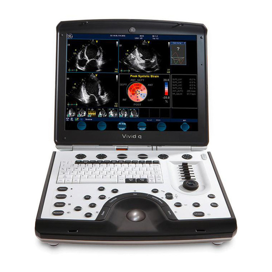
- Page 72 Front and Side View of the Vivid i n Ultrasound Unit Figure 3-8 below shows the Vivid i n ultrasound unit components that are visible from the front and side of the ultrasound unit. Figure 3-8 Front and Side View of the Vivid i n Display Monitor: tilts up and down.
- Page 73 3-5-3-3 Rear View of the Vivid i n Ultrasound Unit Figure 3-9 shows a view of the Vivid i n ultrasound unit rear panel and external peripheral/accessory connectors Figure 3-9 View of the Vivid i n Rear Panel Two interchangeable USB ports (digital printer, CD-RW and other peripherals)
- Page 74 IVID I N ERVICE ANUAL 3-5-4 Connection and Usage of the optional Modo Cart Please refer to the “Vivid i n Cart, User Manual – Supplement to Vivid i n User manual”, Direction Number FL092096. 3-16 Section 3-5 - Preparing for Installation...
- Page 75 System Voltage Settings Verify that the Vivid i n is set to the correct voltage. The Vivid i n voltage settings are found on the base (underside) of the system. Figure 3-10 Safety Rating Plate - Example WARNING: CONNECTING THE VIVID I N TO THE WRONG VOLTAGE LEVEL WILL MOST LIKELY DESTROY THE SCANNER.
- Page 76 3-5-6 Ensuring Protection from EMI The Vivid i n unit has been designed to minimize the effects of Electro-Magnetic Interference (EMI). Many of the covers, shields, and screws are provided primarily to protect the system from image artifacts caused by this interference. For this reason, it is imperative that all covers and hardware are installed and secured before the unit is put into operation.
- Page 77 Connection directly to the Vivid i n system The USB Global modem can be powered via the USB port on the Vivid i n system with no need for additional power. The modem should be connected to the lower USB port on the rear connectors panel.
- Page 78 Wireless Network Adaptor The Wireless Network adaptor connection is explained below. • Connection directly to the Vivid i n system The Wireless Network adaptor should be connected to the PC MCIA socket on the Vivid i n rear connectors panel.
- Page 79 The BT06 software 6.1.0 build 109 Software CD can be obtained by ordering the Vivid i n BT06 SW (M4) CD kit - P/N: 2421595. For instructions, refer to "Software Loading" on page 8-56.
- Page 80 NOTICE supplied by the manufacturer. The Samsung DVD-R/RW drive, which is designed to operate with the Vivid i n system using the USB port, combines the functions of a DVD or CD recorder, and a DVD or CD player. This DVD device may be used on the Vivid i n system for the following purposes: •...
- Page 81 IMPORTANT - the following steps must be performed in the order stated. NOTICE (If the USB cable is connected first while power to the Vivid i n is ON, the drive will not be recognized. In this event, it will be necessary to re-boot the system).
- Page 82 The DVD/CD-RW drive connection in the different scenarios is explained below. • No Cart - connection directly to the Vivid i n system or via USB Hub The DVD/CD-RW Drive can be connected to either of the USB ports (upper or lower) on the rear connectors panel.
- Page 83 DVD’s AC adaptor. If an isolation transformer is not available, the DVD must be disconnected from the Vivid i n system while scanning a patient. The DVD/CD-RW Drive can be connected once the system is powered ON, or after shutdown. All software drivers for the DVD/CD-RW Drive are pre-configured and installed designated to be used with the specific DVD/CD-RW supplied with the system.
- Page 84 This connection must be via a USB-to-SCSI adaptor; one side of the adaptor being connected to the Vivid i n USB port, and the other side to the rear of the MOD drive. When connecting the MOD drive directly to the system, it is necessary to use an additional power source.
- Page 85 However, it is highly recommended to use the memory stick that is provided and approved by GE Healthcare. Other memory sticks may be sensitive to EMC interference - this may affect system performance and/or image quality.
- Page 86 The B/W Printer connection in the different scenarios is explained below. NOTE: After physical connection of the printer to the Vivid i n system, to configure the appropriate hot keys to activate printing direct from the control panel, follow the instructions in "Configuring Hot Keys to Activate Printing Direct from the Control Panel"...
- Page 87 NOTE: After physical connection of the printer to the Vivid i n system, to configure the appropriate hot keys to activate printing direct from the control panel, follow the instructions in "Configuring Hot Keys to Activate Printing Direct from the Control Panel"...
- Page 88 6.) From the listed Outputs, select (highlight) the required output, right-click and select Properties to configure the output device accordingly. Printing may now be activated direct from the Vivid i n Control Panel, using the hot key you have configured for this purpose.
- Page 89 ANUAL 3-6-1-10 Connecting the DeskJet Color Printer IMPORTANT Do not connect the DeskJet Color Printer to the Vivid i n system while scanning is NOTICE in progress! IMPORTANT During Stand-by mode, it is NOT recommended to introduce or remove USB NOTICE devices;...
- Page 90 WARNING Do not attempt to use a different type of DeskJet Color Printer (brand or model) other than the DeskJet Color Printer provided by GE Healthcare. The ultrasound system is an extremely sensitive and complex medical system. Any unauthorized peripherals may cause system failure or damage! •...
- Page 91 A Mitsubishi VCR is used in this configuration - use the type that is suited to your region. The video signal is received through a VGA-to-video converter. 1) Connect one end of the VGA cable to the VCR OUTPUT located on the Vivid i n rear connector panel (see note below).
- Page 92 GE H EALTHCARE FL091021, R IRECTION EVISION IVID I N ERVICE ANUAL 3-6-1-11 Connecting the VCR (cont’d) 3.) Connect one end of the S-Video cable to the S-Video OUTPUT on the video converter. 4.) Connect the other end of the S-Video cable to the VCR S-Video INPUT at the rear of the VCR.
- Page 93 Press the power ON switch on the VCR. b.) Press the power ON switch on the video converter. c.) Turn ON power to the Vivid i n system. 7.) Press the Input Select button (see Figure 3-20 on page 3-33 ) on the video converter three times in order to select VGA Input as your signal source.
- Page 94 GE H EALTHCARE FL091021, R IRECTION EVISION IVID I N ERVICE ANUAL 3-6-1-11 Connecting the VCR (cont’d) NOTE: If the VGA cable is not properly connected to the rear panel, or in the event that the scan-converter device is not switched ON, you may see a single icon displayed, as shown in Figure 3-24.
- Page 95 CH5000GE fuel gauge when detected to be out of calibration. The charger is specifically designed to operate with the Vivid i n smart-battery (P/N 2378963-2). The charger is supplied in a carton containing the following items: •...
- Page 96 At the end of this procedure, when the battery is fully charged, the solid green LED will be illuminated in the status window, indicating a fully charged battery. 2.) Remove the battery from the charger unit battery bay and install it in the Vivid i n. 3-38 Section 3-6 - Completing the Hardware Installation...
- Page 97 LEDs will be illuminated in the status window, indicating a fully charged, fully calibrated battery. 2.) Remove the battery from the charger unit battery bay and install it in the Vivid i n. Note: The most common cause of calibration failure is overheating of the pack during discharge.
- Page 98 3-6-3 Connecting Probes The Vivid i n ultrasound unit operates with various types of probes that are used for scanning patients, including flat phased, convex and linear electronic array probes. Once connected, the probes can be selected for different applications.
- Page 99 5) Align the connector with the probe port and carefully push into place, as shown in Figure 3-28. Figure 3-28 Connecting Probe to the Vivid i n 6) Press the connector locking lever upwards to the full vertical position to lock in place, as shown in Figure 3-29.
- Page 100 GE H EALTHCARE FL091021, R IRECTION EVISION IVID I N ERVICE ANUAL 3-6-3-1 Available Probes For a list of the available probes, please see: Section 9-7 "Probes" on page 9-8. 3-42 Section 3-6 - Completing the Hardware Installation...
- Page 101 Figure 3-30 ECG Cables Connected to the ECG Connector Port CAUTION: When disconnecting the ECG Cable from the Vivid i n, do not pull on the cable directly. Carefully remove the cable by holding the outer sleeve (closest to the system) while releasing the cable.
- Page 102 Connecting the Unit to a Power Source The connection of the Vivid i n ultrasound unit to a power source should be performed by a qualified person who has completed basic Vivid i n System User Training. Use only the power cords, cables and plugs provided by or designated by GE Healthcare to connect the unit to the power source.
- Page 103 Disconnecting the Ultrasound Unit from the Electrical Outlet CAUTION: Make sure the system is powered OFF or in standby mode before disconnecting the Vivid i n unit from the electrical outlet and proceed as described in the steps below: 1) Power down the unit.
- Page 104 3) When prompted, log in to the system as appropriate. (Refer to the instructions for system login and user security setup as described in the Vivid i n). The system first enters 2D-Mode with the probe and application that were last used before the system was shut down.
- Page 105 EVISION IVID I N ERVICE ANUAL Section 3-7 Configuration 3-7-1 Overview Table 3-12 below outlines the Vivid i n Configuration procedures described in the relevant sub-sections. Table 3-12 Configuration Procedures PAGE SUB- SECTION DESCRIPTION NUMBER 3-7-2 Vivid i n Configuration...
- Page 106 IRECTION EVISION IVID I N ERVICE ANUAL 3-7-2 Vivid i n Configuration 3-7-2-1 Preparations Press CONFIG (F2) and log on as Adm (see "Log On to the System as ADM" on page 4-10). 3-7-2-2 Enter Location Figure 3-32 Hospital and Department Name...
- Page 107 GE H EALTHCARE FL091021, R IRECTION EVISION IVID I N ERVICE ANUAL 3-7-2-3 Date and Time Adjustments Figure 3-33 Date and Time Adjustments Table 3-14 Date and Time Adjustments Step Task Expected Result(s) Figure 3-32 on Open the System (Configuration) Window, see page 3-48 The System Settings Window is displayed.
- Page 108 GE H EALTHCARE FL091021, R IRECTION EVISION IVID I N ERVICE ANUAL 3-7-2-4 Language Selection Language Figure 3-34 Language Selection Table 3-15 Language Adjustments STEP TASK EXPECTED RESULT(S) Open the Configuration Window, see "Log On to the System as ADM" on page 4-10.
- Page 109 GE H EALTHCARE FL091021, R IRECTION EVISION IVID I N ERVICE ANUAL 3-7-2-5 Units of Measure Units Figure 3-35 Select Units of Measure Table 3-16 Select Units of Measure STEP TASK EXPECTED RESULT(S) Open the Configuration Window, see "Log On to the System as ADM"...
- Page 110 GE H EALTHCARE FL091021, R IRECTION EVISION IVID I N ERVICE ANUAL 3-7-3 Service Screen Set-up 3-7-3-1 Overview The Service Screen gives you access to: • Select Video Format to be used by the VCR • Select the VCR type •...
-
Page 111
GE H EALTHCARE FL091021, R IRECTION EVISION IVID I N ERVICE ANUAL 3-7-3-3 Adjust Keyboard Backlight Intensity • Press
+ L. • Use the sliders in the Front Panel Lights Setup dialog box to adjust Backlight Intensity of the Alphanumeric keyboard, Extended ultrasound keyboard, and/or Active keys, as required. - Page 112 GE H EALTHCARE FL091021, R IRECTION EVISION IVID I N ERVICE ANUAL 3-7-3-5-1 Regional Options • Select appropriate Format and Location, then click Apply. Figure 3-39 Regional Options 3-54 Section 3-7 - Configuration...
- Page 113 GE H EALTHCARE FL091021, R IRECTION EVISION IVID I N ERVICE ANUAL 3-7-3-5-2 Languages 1.) Under the Languages tab, click Details to select appropriate Language. 2.) If necessary, activate applicable Supplemental Language Support check box, then click Apply. Figure 3-40 Languages...
- Page 114 GE H EALTHCARE FL091021, R IRECTION EVISION IVID I N ERVICE ANUAL 3-7-3-5-3 Advanced 1.) Under the Advanced tab, select a language version of the non-unicode programs you want to use, then click Apply. Figure 3-41 Advanced 3-56 Section 3-7 - Configuration...
- Page 115 Windows Installation Wizard. Normally, all software drivers are pre-installed and there is no need to use this functionality. In special cases where there is a need, follow the instructions provided by GE Healthcare or the instructions in the respective printer installation manual. Select Add Printer Figure 3-42 Select Add Printer 1.) Select ADD PRINTER to start the Add Printer (Installation) Wizard.
- Page 116 ANUAL 3-7-4 Configuring Peripherals 3-7-4-1 Approved Peripherals The following lists the internal peripherals available for use with the Vivid i n and details their method of connection: • Printer - Black & White, digital, Sony (via USB). • Printer - Color, digital, Sony (via USB).
- Page 117 GE H EALTHCARE FL091021, R IRECTION EVISION IVID I N ERVICE ANUAL 3-7-4-3 Virtual Printing (Optional) Virtual printing is not configurable. The functionality of virtual printing provides the ability to print to a specific printer, even though it is not physically connected.
- Page 118 GE H EALTHCARE FL091021, R IRECTION EVISION IVID I N ERVICE ANUAL 3-7-4-3 Virtual Printing (Optional) (cont’d) Figure 3-46 Resuming Spooled Print Job 4.) Right-click and select Restart to resume print job/s for printing, as required 3-60 Section 3-7 - Configuration...
- Page 119 Figure 3-48 Type Software Option Key Incorrect password entry will result in loss of system options. CAUTION If password is incorrect, please contact your local GE Service representative. 5.) Type the Password (Software Option Key). 6.) Press OK to save the new setting.
- Page 120 By utilizing dataflows, the user can configure the Vivid i n ultrasound unit to optimally meet the needs of the facility, while keeping the user interface unchanged. Once the dataflow is selected, the actual location of the database is entirely transparent.
- Page 121 EVISION IVID I N ERVICE ANUAL 3-8-1-3 Dataflow Examples Vivid i n LocalArchive-Int.HD dataflow: The local database is used for patient archiving. Images are stored to internal hard drive. Vivid i n LocalArchive-MOD dataflow: The local database is used for patient archiving.
- Page 122 Vivid i n and a DICOM Server in a Network In this configuration, the Vivid i n is configured to work with a DICOM server in a network environment. Usually, this will be the hospital network. Images are first saved on the local image buffer on the scanner.
- Page 123 ERVICE ANUAL 3-8-2 Physical Connection 3-8-2-1 Ethernet Switch Connections An Ethernet Switch (P/N: 066E0741), is used to connect the Vivid i n system to an EchoPAC PC and a network printer. Ethernet Cable Informative LEDS connectors MDI Button Controls the fifth connector, making it crossed or non-crossed.
- Page 124 3-8-2-2 Local Network Connection to EchoPAC PC Workstation Do not use the fifth connector and the switch can be in any position, Vivid7 Vivid i n EchoPAC PC Use only Standard non-crossed Ethernet cabling. Figure 3-51 Local Network Connection 3-8-2-3...
- Page 125 ANUAL 3-8-2-4 Wireless Network Configuration The following procedure is used to configure the Vivid i n system for a wireless network environment. NOTE: Do not use any other type of wireless adaptor other than the Cisco 350 Series WLAN card.
- Page 126 GE H EALTHCARE FL091021, R IRECTION EVISION IVID I N ERVICE ANUAL 3-8-2-4 Wireless Network Configuration (cont’d) Type Network Key here Figure 3-54 Wireless Network Connection Dialog Box 6.) Type the Network key (supplied by the Local IT group) in the Network Key field and press Connect.
- Page 127 "Ethernet Switch Connections" on page 3-65. Connection via Hospital Network You will need one network cable to connect the Vivid i n to a wall outlet on the hospital’s network. 3-8-2-8 Connection between a Vivid i n and a DICOM Server on a Network You will need one network cable.
- Page 128 ERVICE ANUAL 3-8-3 Connectivity Configuration NOTE: If connected to a stand-alone network (Peer-to-Peer network with a Vivid i n scanner, an EchoPAC PC work station and eventually a network printer), you should use default delivery settings. 3-8-3-1 Introduction To be able to use the network functions when connected to a hospital network, the scanner must have a proper network address.
- Page 129 4.) In addition, the scanner’s AE Title must be entered in the DICOM server’s setup. AETitle IP Address Subnet Mask Default Gateway Figure 3-57 TCP/IP Set-up for Vivid i n 3-8-3-4 Set the Remote Archive’s Network Information In the Remote Archive Setup area of the screen (see example in Figure 3-58), enter the following: 1.) Remote Archive IP address.
- Page 130 Figure 3-59 Save New TCP/IP settings The new settings are saved to a common settings file. After a restart, the settings are also included in other screens. 2.) Restart the Vivid i n system to activate the changes. 3-72 Section 3-8 - Connectivity Setup...
- Page 131 The instruction Select = trackball to the specific item and press the Set button on the control panel. 1.) On the Vivid i n control panel, press the Config button. 2.) From the System Configuration window, click the Connectivity tab at the bottom of the window.
- Page 132 IVID I N ERVICE ANUAL 3-8-3-6 Configuring the Vivid i n and Network PC for Peer-to-Peer Connection (cont’d) 8.) Select Internet Protocol (TCP/IP). 9.) Click the Properties button. The Internet Protocol (TCP/IP) Properties dialog box opens. Figure 3-62 Internet Protocol (TCP/IP) Properties 10.)Activate the Use the following IP address check box.
- Page 133 6.) Activate the Use the following IP address check box. 7) Type in the network computer’s IP address 10.0.0.2. Note: The IP address must be different from the one used for the Vivid i n system. 8) Type in the Subnet mask 255.255.255.0. Note: The Subnet mask should be the same for both the network computer and the Vivid i n.
- Page 134 Configuring the Vivid i n and Network PC for Peer-to-Peer Connection (cont’d) 10) Connect the Vivid i n and network computer LAN connection using a cross over Network cable. (Normally with RED connector covers on both sides, cable not longer than 100 meters).
- Page 135 ERVICE ANUAL 3-8-3-7 Configuring the Vivid i n and Network PC for a LAN Connection NOTE: The following steps are performed on the Vivid i n scanner. The instruction Select = trackball to the specific item and press the Set button on the control panel.
- Page 136 Figure 3-67 Internet Protocol (TCP/IP) Properties 10.)Activate the Use the following IP address check box. 11.)Type in the Vivid i n IP address 10.0.0.1 or the one provided by the local network administrator. Note: The IP must be different from the IP address used for network computer.
- Page 137 IVID I N ERVICE ANUAL 3-8-3-7 Configuring the Vivid i n and Network PC for a LAN Connection (cont’d) 13.)Click OK 14.)Press the Config button on the control panel to close all windows and return to the regular scanning mode.
- Page 138 7) Click OK, close all windows and approve all changes. Return to regular mode. 8) Connect the Vivid i n and network computer LAN connection using a regular Network cable. The Vivid i n and the network computer are now ready for export, import of files.
- Page 139 Set Up Connection to a DICOM Server in a Network In this case, the Vivid i n is configured to work with a DICOM server in a network environment. Images are first saved on the local image buffer on the scanner. At the end of the examination, the images are sent to the DICOM server via a DICOM spooler.
- Page 140 GE H EALTHCARE FL091021, R IRECTION EVISION IVID I N ERVICE ANUAL 3-8-4 Set Up Connection to a DICOM Server in a Network (cont’d) The selected flow is shown, as seen in the example in Figure 3-71 below (Worklist/Local Archive - DICOM Server/Int.
- Page 141 GE H EALTHCARE FL091021, R IRECTION EVISION IVID I N ERVICE ANUAL 3-8-4 Set Up Connection to a DICOM Server in a Network (cont’d) 8.) Highlight the modality filter in the list and click on "Remove" (see Figure 3-72). Figure 3-73 Search Criterias Window 9.) In the Select Tag drop down menu select "00080060 Modality".
- Page 142 GE H EALTHCARE FL091021, R IRECTION EVISION IVID I N ERVICE ANUAL 3-8-4 Set Up Connection to a DICOM Server in a Network (cont’d) 10.)Type US in the Value text box and click on "Add to List". The Search Criterias window is updated (see Figure 3-73).
- Page 143 GE H EALTHCARE FL091021, R IRECTION EVISION IVID I N ERVICE ANUAL 3-8-4 Set Up Connection to a DICOM Server in a Network (cont’d) NOTE: It is not possible to change the setting in the IP-Address field by editing it. See description below, starting with step 13, to change the setting.
- Page 144 GE H EALTHCARE FL091021, R IRECTION EVISION IVID I N ERVICE ANUAL 3-8-4 Set Up Connection to a DICOM Server in a Network (cont’d) c.) Edit the name and/or the IP address of the server, see Figure 3-78. Name IP address Figure 3-78 Edit Name and/or IP address d.) Click OK to save the new settings and close the Edit Name dialog box.
- Page 145 GE H EALTHCARE FL091021, R IRECTION EVISION IVID I N ERVICE ANUAL 3-8-4-3 Verify the Connection to a Device 1.) Select (highlight) the device to which you want to verify the connection. Select device to be verified. Check Figure 3-80 Verify Connection to a Device 2.) Select CHECK to start the connection to the device verification process.
- Page 146 3-8-5-1 Introduction The procedures below describe how to set up the Vivid i n workstation so it can connect to the Hospital Information System (HIS), via the Vivid HL7 Gateway. By connecting to the HIS, demographic information (i.e. Patient ID, Name, Gender, etc.) can be retrieved from the HIS, reducing “double-work”...
- Page 147 1.) In the Search Criterias dialog box, select 00400001 Scheduled Station AE Title from the Select Tag pull-down menu. 2.) Enter the Vivid i n computer name for the Value. 3.) Click the Add to List button. 4.) Click the OK button.
- Page 148 Test Connectivity with the Vivid HL7 Gateway The purpose of this test is to verify that the Vivid i n has connectivity with the Vivid HL7 Gateway. 1.) From either the Current or Dataflow view, expand the Dataflow incorporating the Gateway Modality Worklist service.
- Page 149 1.) Path provided in Export to HL7 export path was incorrect. 2.) Mitra support personnel did not create the user account for the Vivid i n. 3.) The POLL_DIR directory on the Vivid HL7 Gateway was not shared or the permissions are incorrect.
- Page 150 3-8-6-1 Overview The Query/Retrieve function makes it possible to search for and retrieve DICOM data from a DICOM server for further analysis on the Vivid i n. 3-8-6-2 Query/Retrieve Setup on the Vivid i n 1.) Press CONFIG (F2) and log on as Adm, as described in "Log On to the System as ADM" on page 4- 2.) Select Connectivity.
- Page 151 EVISION IVID I N ERVICE ANUAL 3-8-6-2 Query/Retrieve Setup on the Vivid i n (cont’d) The selected dataflow (Query/Retrieve), is displayed as shown in Figure 3-83. Figure 3-83 Query/Retrieve Workflow 5.) Select QueryRetrieve so it is highlighted and then select Properties to display the Properties dialog box.
- Page 152 IRECTION EVISION IVID I N ERVICE ANUAL 3-8-6-2 Query/Retrieve Setup on the Vivid i n (cont’d) IP-ADDRESS DOWN-ARROW AE TITLE PORT NO Figure 3-85 DICOM Query/Retrieve properties 6.) Select the IP-address down-arrow to choose the DICOM Query/Retrieve server from the pull-down menu.
- Page 153 ERVICE ANUAL 3-8-6-2 Query/Retrieve Setup on the Vivid i n (cont’d) Change Search Criterias It is possible to set up special Search Criterias for DICOM Query/Retrieve. In most cases you may leave the Search Criterias as is, and skip this adjustment.
- Page 154 GE H EALTHCARE FL091021, R IRECTION EVISION IVID I N ERVICE ANUAL 3-8-6-3 Query/Retrieve Verification SMILEY VERIFICATION CHECK BOX Figure 3-87 DICOM Query/Retrieve Properties Follow the Steps Below to do a First Test (Ping) of the Connection 1.) Select the Smiley button to Ping the server.
- Page 155 GE H EALTHCARE FL091021, R IRECTION EVISION IVID I N ERVICE ANUAL 3-8-6-3 Query/Retrieve Verification (cont’d) Follow the Steps Below to Test the DICOM Query/Retrieve Workflow NOTE: This check uses both Ping and DICOM Ping. QUERYRETRIEVE CHECK Figure 3-88 Check the DICOM Query/Retrieve Workflow 1.) Select QueryRetrieve from the Selected devices list.
- Page 156 GE H EALTHCARE FL091021, R IRECTION EVISION IVID I N ERVICE ANUAL 3-8-6-3 Query/Retrieve Verification (cont’d) If the test fails, a pop-up warning is displayed, see left illustration in Figure 3-90. Select OK to continue. A red “X” to the left of the Selected devices indicates that the test failed.
- Page 157 3-8-7-1 Introduction The procedures below describe how to set up the Vivid i n for MPEGVue export. This provides the user with the ability to export an entire patient exam into standard supported media (such as, CD, DVD, or USB Memory Stick [disk-on-key]) in standard MPEG or JPG format. The exported exam can later be read on any PC.
- Page 158 IVID I N ERVICE ANUAL 3-8-7-3 Configuring the Vivid i n for MPEGVue Export 1) Press the Config (or F2) button and log on as Adm, as described in "Log On to the System as ADM" on page 4-10. 2.) Select Connectivity.
- Page 159 IVID I N ERVICE ANUAL 3-8-7-3 Configuring the Vivid i n for MPEGVue Export (cont’d) 5) From selected output devices, highlight evue and then click the Properties button - refer to Figure 3-92 on page 3-101 . Figure 3-92 eVue Properties...
- Page 160 IVID I N ERVICE ANUAL 3-8-7-3 Configuring the Vivid i n for MPEGVue Export (cont’d) 7) Activate the Copy Media Player Installation check box. Note: Step 7 is recommended for the first transfer of MPEGVue files. This step is not needed for Windows XP.
- Page 161 9.) If required, click OK then select any additional Patient Files for export. 10.)When export complete, click OK then remove the media containing the exported MPEGVue data from the Vivid i n system. Note: If any problems occurred with copying the Patient Files during the export process, an error message such as the one below will be displayed, showing the status of each of the transferred Patient Files.
- Page 162 Introduction It is possible to configure the Vivid i n to allow the user to send images or loops to a remote PC, in almost real time. When pressing Store, the loop will save not only to the local archive (in raw-data format), but will also be transmitted to a designated PC (“e-Vue PC”) on the network (in compact MPEG format),...
- Page 163 1.) Verify which PC in the hospital/institute has been designated as the e-Vue station. 2.) Make sure the Vivid i n is connected to the Network via cable or wireless. 3.) On the Vivid i n scanner, press the Config button.
- Page 164 The Vivid i n dataflow is set and ready for export/import of eVue files into a network computer. From now on, whenever the Vivid i n is used for scanning and the Store button is pressed, another person will be able to view the stored loop on the remote e-Vue PC (after a short transmission time).
- Page 165 ERVICE ANUAL 3-8-8-4 Using eVue 1.) On the Vivid i n, in regular scanning mode, press Patient. When the following window is displayed, select Create New Patient. The Search/Create Patient dialog box opens. Figure 3-97 Search/Create Patient Dialog Box 2.) Type the patient’s Last Name and ID in the appropriate fields (see Figure 3-97).
- Page 166 GE H EALTHCARE FL091021, R IRECTION EVISION IVID I N ERVICE ANUAL 3-8-9 Using MPEGVue/eVue on a Remote PC 3-8-9-1 Installing MPEGVue on a Remote PC NOTE: MPGEGVue player is not compatible with Windows 98. For systems running a software version earlier than 6.1.0 (build 109), the MPEGVue player is not compatible with Internet Explorer 7, therefore, do not upgrade Internet Explorer on your PC to this version.
- Page 167 GE H EALTHCARE FL091021, R IRECTION EVISION IVID I N ERVICE ANUAL 3-8-9-1 Installing MPEGVue on a Remote PC (cont’d) In addition to the above, the installation program will test the configuration of the remote PC and will display a message if any component on the computer is not within the required specifications.
- Page 168 GE H EALTHCARE FL091021, R IRECTION EVISION IVID I N ERVICE ANUAL 3-8-9-1 Installing MPEGVue on a Remote PC (cont’d) Figure 3-99 Download/Installation Message Examples #2 3-110 Section 3-8 - Connectivity Setup...
- Page 169 GE H EALTHCARE FL091021, R IRECTION EVISION IVID I N ERVICE ANUAL 3-8-9-2 Manually Setting the Network PC for eVue Import 1) On the network computer, create a New User by accessing the Control Panel, as follows: a.) Double-click on My Computer icon on desktop.
- Page 170 GE H EALTHCARE FL091021, R IRECTION EVISION IVID I N ERVICE ANUAL 3-8-9-2 Manually Setting the Network PC for eVue Import (cont’d) 4) Click on the Advanced button. The Local Users and Groups dialog box opens: Figure 3-101 Local Users and Groups Dialog Box 5.) Select the Users folder and right-click to select New User.
- Page 171 GE H EALTHCARE FL091021, R IRECTION EVISION IVID I N ERVICE ANUAL 3-8-9-2 Manually Setting the Network PC for eVue Import (cont’d) 6.) Configure a new user account, as follows (see Figure 3-102): a.) User name: E1c2h3o4C5l6i7e8n9t b.) Password: u1l3t5r7a c.) Deactivate the User must change password at next logon check box.
- Page 172 GE H EALTHCARE FL091021, R IRECTION EVISION IVID I N ERVICE ANUAL 3-8-9-2 Manually Setting the Network PC for eVue Import (cont’d) 9.) Setting the Sharing properties for the new folder, as follows: a.) Right-click on eVue_Import icon and select Properties;...
- Page 173 GE H EALTHCARE FL091021, R IRECTION EVISION IVID I N ERVICE ANUAL 3-8-9-2 Manually Setting the Network PC for eVue Import (cont’d) c.) Click on the Permissions button. The Permissions for eVue Import dialog box opens: Note: It is recommended to remove this user.
- Page 174 GE H EALTHCARE FL091021, R IRECTION EVISION IVID I N ERVICE ANUAL 3-8-9-2 Manually Setting the Network PC for eVue Import (cont’d) e.) Click the Object Types button. f.) From the Object Types dialog box, select all to be active (activate all the check boxes, as shown below) and press OK.
- Page 175 GE H EALTHCARE FL091021, R IRECTION EVISION IVID I N ERVICE ANUAL 3-8-9-2 Manually Setting the Network PC for eVue Import (cont’d) j.) Click the Check Names button. The name and path will be detected by underlining, as shown below.
- Page 176 Close all windows. Note: The network computer is now ready to receive files from the Vivid i n system. At this stage, set the appropriate path for export of files into the network computer. For example, for eVue, Data Flow or MpegVue export into the network computer using the browsing option to select the appropriate path.
- Page 177 GE H EALTHCARE FL091021, R IRECTION EVISION IVID I N ERVICE ANUAL 3-8-9-3 Manually Stopping the Firewall on the Network PC (cont’d) 3.) Select your network connection and right-click. 4.) From the drop-down menu, select Properties. The Local Area Connection Properties dialog box opens: Figure 3-108 Local Area Connection Properties Dialog Box 5.) Select the Advanced Tab.
- Page 178 GE H EALTHCARE FL091021, R IRECTION EVISION IVID I N ERVICE ANUAL 3-8-9-3 Manually Stopping the Firewall on the Network PC (cont’d) Stopping an External Service Firewall 1.) On the network computer, access the Control Panel, as follows: a.) Press Start.
- Page 179 The following message will be displayed indicating that the Firewall is being stopped. 6.) When finished, click Close. 7.) Now you can try to reconnect the network computer to the Vivid i n system. Chapter 3 - System Setup 3-121...
- Page 180 GE H EALTHCARE FL091021, R IRECTION EVISION IVID I N ERVICE ANUAL 3-8-9-3 Manually Stopping the Firewall on the Network PC (cont’d) Stopping the Firewall on Windows XP Service Pack 2 1.) On the network computer, access the Control Panel, as follows: a.) Press Start.
- Page 181 GE H EALTHCARE FL091021, R IRECTION EVISION IVID I N ERVICE ANUAL 3-8-9-4 Un-installing MPEGVue on a Remote PC 1.) Log in to Windows with Administrator permissions. Note: You may need to obtain these from the local IT person. 2.) Close all Internet Explorer windows, if open.
- Page 182 GE H EALTHCARE FL091021, R IRECTION EVISION IVID I N ERVICE ANUAL 3-8-9-4 Un-installing MPEGVue on a Remote PC (cont’d) 4.) If two messages are displayed one after another (shown in Figure 3-113 Figure 3-114), click the OK button on each of them to close the message.
- Page 183 GE H EALTHCARE FL091021, R IRECTION EVISION IVID I N ERVICE ANUAL 3-8-9-4 Un-installing MPEGVue on a Remote PC (cont’d) 5.) From the C:\Program Files\GEULS\eStorePlayer\Version1_0\ folder, delete all files, as shown in Figure 3-115 on page 3-125 . Figure 3-115 Deleting All Files 6.) Restart Windows, then confirm that the MPEGVue application is no longer installed.
- Page 184 GE H EALTHCARE FL091021, R IRECTION EVISION IVID I N ERVICE ANUAL 3-8-9-5 Using MPEGVue Viewer on a Remote PC Reading an MPEGVue Exam An MPEG exam can be read on any computer with Windows 2000/XP/2003, provided that DirectX 8.1 (or later) and Windows Media Player 7.1 (or later) are installed.
- Page 185 GE H EALTHCARE FL091021, R IRECTION EVISION IVID I N ERVICE ANUAL 3-8-9-5 Using MPEGVue Viewer on a Remote PC (cont’d) 1) Click on the required examination Exam Date (labelled 1 in the example above) to select and display images of that exam.
- Page 186 GE H EALTHCARE FL091021, R IRECTION EVISION IVID I N ERVICE ANUAL 3-8-9-5 Using MPEGVue Viewer on a Remote PC (cont’d) Selecting an Image When a thumbnail image is selected for review, the thumbnail image in the clipboard area becomes bounded (highlighted) with a yellow frame.
- Page 187 3D images, or images with discontinuities. Saved Worksheets On the Vivid i n scanner, it is possible to view the Worksheet and press Store. This will generate a still frame showing a snapshot of the Worksheet with the visible measurements on it. This same snapshot will also be visible in the MPEGvue Viewer.
- Page 188 GE H EALTHCARE FL091021, R IRECTION EVISION IVID I N ERVICE ANUAL 3-8-9-5 Using MPEGVue Viewer on a Remote PC (cont’d) Using MPEGVue over E-mail Note: To use the MPEGVue over E-mail feature, Microsoft Outlook must be currently running. If not, the following message is displayed prompting the user to first logon to Outlook: It is possible to send images, loops, or full exams from any eVue PC.
- Page 189 GE H EALTHCARE FL091021, R IRECTION EVISION IVID I N ERVICE ANUAL 3-8-9-5 Using MPEGVue Viewer on a Remote PC (cont’d) 3.) Click Next. The E-mail address window is displayed (Figure 3-119 below). Figure 3-119 E-mail Address Window 4) Select an existing recipient address from the drop-down menu, or type a new address in the Send To field.
- Page 190 GE H EALTHCARE FL091021, R IRECTION EVISION IVID I N ERVICE ANUAL 3-8-9-5 Using MPEGVue Viewer on a Remote PC (cont’d) 7) Click Next. The E-mail (addressed to the selected addressee) with the full examination attached is sent to the Outbox;...
- Page 191 GE H EALTHCARE FL091021, R IRECTION EVISION IVID I N ERVICE ANUAL 3-8-9-5 Using MPEGVue Viewer on a Remote PC (cont’d) Sending an image by E-mail Note: If this is the first time your recipient is receiving an MPEGVue image, it is necessary to attach the MPEGVue Player - refer to the instructions for "Sending the MPEGVue Player...
- Page 192 GE H EALTHCARE FL091021, R IRECTION EVISION IVID I N ERVICE ANUAL 3-8-9-5 Using MPEGVue Viewer on a Remote PC (cont’d) 4) Click Next. The E-mail (addressed to the selected addressee) with the image is sent to the Outbox; during this...
- Page 193 GE H EALTHCARE FL091021, R IRECTION EVISION IVID I N ERVICE ANUAL 3-8-9-5 Using MPEGVue Viewer on a Remote PC (cont’d) Sending the MPEGVue Player Software by E-mail Note: This procedure is required once - only the first time your recipient is receiving MPEGVue image/s.
- Page 194 GE H EALTHCARE FL091021, R IRECTION EVISION IVID I N ERVICE ANUAL 3-8-9-5 Using MPEGVue Viewer on a Remote PC (cont’d) 2) From the desktop, double-click on the icon. The following message is displayed: 3) When prompted by the Warning message shown below, make sure all Internet Explorer windows are closed except the current window, then click Yes to proceed.
- Page 195 GE H EALTHCARE FL091021, R IRECTION EVISION IVID I N ERVICE ANUAL 3-8-9-5 Using MPEGVue Viewer on a Remote PC (cont’d) Managing and Viewing Exams Received Once the MPEGVue Player software has been installed on a remote computer (as described in "First Time Receipt of MPEGVue Player Software and Images by E-mail"...
- Page 196 GE H EALTHCARE FL091021, R IRECTION EVISION IVID I N ERVICE ANUAL 3-8-9-5 Using MPEGVue Viewer on a Remote PC (cont’d) Get new exams by E-mail 1) From the MPEGVue Startup Menu, click on the Get new exams by email button.
- Page 197 GE H EALTHCARE FL091021, R IRECTION EVISION IVID I N ERVICE ANUAL 3-8-9-5 Using MPEGVue Viewer on a Remote PC (cont’d) 3.) Activate the Receive Exam radio button, then click Next. The following message is displayed while the e-mail Inbox is being scanned for studies:...
- Page 198 GE H EALTHCARE FL091021, R IRECTION EVISION IVID I N ERVICE ANUAL 3-8-9-5 Using MPEGVue Viewer on a Remote PC (cont’d) 5.) Click Next. The Password window is displayed:. Figure 3-132 Password Window 6) Enter the same password (for decryption of the study) as that used by the sender of the e-mails.
- Page 199 GE H EALTHCARE FL091021, R IRECTION EVISION IVID I N ERVICE ANUAL 3-8-9-5 Using MPEGVue Viewer on a Remote PC (cont’d) The E-mail message(s) containing the MPEG examination is deleted from “In-box” of Outlook and is moved to the “Deleted-items” box of Outlook. When done, the following message is displayed: 8) Click OK to close the message.
- Page 200 GE H EALTHCARE FL091021, R IRECTION EVISION IVID I N ERVICE ANUAL 3-8-9-5 Using MPEGVue Viewer on a Remote PC (cont’d) View previous exams from E-mail 1) From the MPEGVue Startup Menu, click on the View previous exams from email button.
- Page 201 GE H EALTHCARE FL091021, R IRECTION EVISION IVID I N ERVICE ANUAL 3-8-9-5 Using MPEGVue Viewer on a Remote PC (cont’d) Using Patient Manager 1) From the MPEGVue Startup Menu, click the button. The MPEGVue Patient Manager window opens, as shown below:...
- Page 202 GE H EALTHCARE FL091021, R IRECTION EVISION IVID I N ERVICE ANUAL 3-8-9-5 Using MPEGVue Viewer on a Remote PC (cont’d) b.) Select the required exam or exams, as shown in Figure 3-137. (Use Ctrl +click to select more than one study; Shift + click to select a group of studies)
- Page 203 GE H EALTHCARE FL091021, R IRECTION EVISION IVID I N ERVICE ANUAL 3-8-9-5 Using MPEGVue Viewer on a Remote PC (cont’d) d.) To delete the selected exams, click the Delete Selected Patients button. The user is prompted with the following warning message.
- Page 204 GE H EALTHCARE FL091021, R IRECTION EVISION IVID I N ERVICE ANUAL 3-8-9-5 Using MPEGVue Viewer on a Remote PC (cont’d) 4.) Manage Other Exams, as follows: a.) Make sure the Manage Other Exams tab is activated as shown in Figure 3-139.
- Page 205 GE H EALTHCARE FL091021, R IRECTION EVISION IVID I N ERVICE ANUAL 3-8-9-5 Using MPEGVue Viewer on a Remote PC (cont’d) d.) From the Patient List, select the required exam/s to be copied. If the currently-selected source directory is CD/DVD-ROM (read-only media), the Copy...
- Page 206 GE H EALTHCARE FL091021, R IRECTION EVISION IVID I N ERVICE ANUAL 3-8-9-5 Using MPEGVue Viewer on a Remote PC (cont’d) 5.) If required, access the System Configuration utility, as follows: a.) Make sure the System Configuration tab is activated as shown in Figure 3-141.
- Page 207 GE H EALTHCARE FL091021, R IRECTION EVISION IVID I N ERVICE ANUAL 3-8-9-5 Using MPEGVue Viewer on a Remote PC (cont’d) Select the required eVue folder destination drive: If applicable, enable the peer-to-peer connection check box then type the correct current IP address and Subnet mask details: Click Save to save the new configuration.
- Page 208 In cases of a peer-to-peer connection, before using Enable eVue always make sure the two computers (Vivid i n scanner and your PC) are properly configured and connected directly. Before using Disable eVue, your PC should be connected back to the local network.
- Page 209 GE H EALTHCARE FL091021, R IRECTION EVISION IVID I N ERVICE ANUAL 3-8-9-5 Using MPEGVue Viewer on a Remote PC (cont’d) Using MPEGVue Player 1.) On the remote computer, open the media (CD or Memory Stick) containing the MPEGVue files, or the folder which was set as being shared for import of eVue files.
- Page 210 GE H EALTHCARE FL091021, R IRECTION EVISION IVID I N ERVICE ANUAL 3-8-9-5 Using MPEGVue Viewer on a Remote PC (cont’d) Figure 3-143 Image Review Window 5.) From thumbnails mini-pictures (on the left of the screen), select one for review.
-
Page 211
GE H EALTHCARE FL091021, R IRECTION EVISION IVID I N ERVICE ANUAL 3-8-9-5 Using MPEGVue Viewer on a Remote PC (cont’d) 6.) Press
to refresh the screen. Additional thumbnail pictures will be displayed accordingly. Note: The MpegVue Player can be used as a regular player, using the Play, Stop, Forward, and Rewind buttons. - Page 212 Transportation Box and Packaging Materials Verify that the required packing materials are available. All these materials are required to safely package and transport the Vivid i n ultrasound unit in the shipping transportation box for shipment by vehicle, or any other means.
- Page 213 Section 3-10 Completing the Installation Paperwork NOTE: On completion of a Vivid i n ultrasound scanner installation, it is important to record the relevant System Installation details (see Table 3-18 below) and Product Locator Installation details (see Figure 3-145 on page 3-156 ), for future reference.
- Page 214 GE H EALTHCARE FL091021, R IRECTION EVISION IVID I N ERVICE ANUAL Section 3-11 Product Locator Installation Card NOTE: The Product Locator Installation Card shown may not be the same as the provided Product Locator card. From the factory, a sheet with four Product Locator cards for transportation and one for Installation are included.
- Page 215 3-11-1 User Manual(s) Check that the correct Vivid i n for the system (and relevant software revision), is included with the installation. Specific language versions of the Vivid i n may also be available. Check with your GE Sales Representative for availability.
- Page 216 GE H EALTHCARE FL091021, R IRECTION EVISION IVID I N ERVICE ANUAL This page was intentionally left blank. This page was intentionally left blank. 3-158 Section 3-11 - Product Locator Installation Card...
- Page 217 Purpose of Chapter 4 This chapter describes the functional checks that must be performed either as a part of the installation procedure, or as required during servicing and periodic maintenance of the Vivid i n ultrasound scanner. Note: Refer to...
- Page 218 GE H EALTHCARE FL091021, R IRECTION EVISION IVID I N ERVICE ANUAL 4-1-2 Specific Equipment Required • An empty (blank) MO Disk; P/N: 066E0490 (1.3 GB) P/N: 066E0519 (5.4 GB) P/N: 066E0514 (8.6 GB) • ECG Pads • ECG Cable (Europe): P/N: 2418832-2 •...
- Page 219 DANGER: ENSURE THAT THE POWER CORD AND PLUG ARE INTACT AND THAT THE POWER PLUG IS THE PROPER HOSPITAL-GRADE TYPE (WHERE REQUIRED). Use only power supply cords, cables and plugs provided by or designated by GE Healthcare. NOTICE CAUTION: The system requires all covers.
- Page 220 Power ON/Boot-up (cont’d) Follow These Steps to Connect Mains Power to the Unit Connecting the Vivid i n ultrasound unit involves preliminary checks of the power cord, voltage level and compliance with electrical safety requirements. 1) Ensure that the wall outlet is of appropriate type, and that the power switch is turned OFF.
- Page 221 GE H EALTHCARE FL091021, R IRECTION EVISION IVID I N ERVICE ANUAL 4-2-2-2 Turning the System ON 1) Verify that the ultrasound unit has been connected to the mains power wall outlet via the AC connector on the rear of the system (as previously described) and that mains power is turned ON.
- Page 222 ANUAL 4-2-2-2 Turning the System ON (cont’d) Figure 4-3 Start-up Progress Bar for Vivid i n 3.) The software initiates and sets up the Front-End electronics and the rest of the scanner. 4.) The Keyboard backlight is lit. 5.) As soon as the software has been loaded, a 2D screen is displayed on the monitor, as shown below.
- Page 223 GE H EALTHCARE FL091021, R IRECTION EVISION IVID I N ERVICE ANUAL 4-2-3 Power Shut Down When switching the unit OFF, the system performs an automatic shutdown sequence. NOTE: After turning OFF the system, wait at least 10 seconds before turning it on again. The system may not be able to boot-up if power is recycled too quickly.
- Page 224 GE H EALTHCARE FL091021, R IRECTION EVISION IVID I N ERVICE ANUAL 4-2-3-1 Standby Mode Follow the steps below to select Standby Mode This procedure describes the steps required to power down the unit to Standby mode: NOTE: Don’t press the On/Off button too long. If you press the button too long (more than 3-4 seconds), a full shutdown is started.
- Page 225 GE H EALTHCARE FL091021, R IRECTION EVISION IVID I N ERVICE ANUAL 4-2-3-2 Complete Power Down NOTE: This function is not available from Standby mode. Follow this procedure to perform a complete system power-down 1.) Hold down the On/Off button for 3-5 seconds to evoke the display of the System Exit dialog box (see Figure 4-5 on page 4-7 ).
- Page 226 GE H EALTHCARE FL091021, R IRECTION EVISION IVID I N ERVICE ANUAL 4-2-4 Log On to the System as ADM Table 4-2 Logging on to the System as ADM 1 of 2 Step Task Expected Result(s) Press Config on the alphanumeric keyboard.
- Page 227 4-2-5-1 Introduction Vivid i n is equipped with a Magneto Optical Disk Drive (MOD Drive) and a DVD/CD-RW Drive. The MOD Drive can be connected to either of the USB ports (upper or lower) on the rear connectors panel. This connection must be via a USB-to-SCSI adaptor; one side of the adaptor being connected to the Vivid i n USB port, and the other side to the rear of the MOD drive.
- Page 228 GE H EALTHCARE FL091021, R IRECTION EVISION IVID I N ERVICE ANUAL 4-2-5-2 Install MO Disk in MO Drive Never move the unit with a MO disk in the Magneto Optical Disk Drive because the drive actuator NOTICE will not be locked and the Magneto Optical Disk Drive could break.
- Page 229 GE H EALTHCARE FL091021, R IRECTION EVISION IVID I N ERVICE ANUAL 4-2-5-5 Eject and Remove DVD/CD from DVD/CD Drive Do not eject the DVD/CD using the button on front of the DVD/CD Drive. NOTICE In some cases, the DVD/CD media is ejected automatically. If not automatically ejected, use the manual ejection method as described in the following steps: 1.) Select the Eject button on the screen...
- Page 230 GE H EALTHCARE FL091021, R IRECTION EVISION IVID I N ERVICE ANUAL 4-2-8 Verifying Removable Media 1.) Insert the removable media to be verified. 2.) Select the pre-configured removable media from the Config > Connectivity > Tools pop-up menu. 3.) Press Verify.
- Page 231 STEP TASK FUNCTION Insert an empty, formatted MO disk labelled “PRESETS” and marked with Vivid i n’s serial number and the date, into the MO Drive. For more information about formatting, see "Formatting Removable Media" on page 4-13. Press Config (or F2); select Admin The Backup window is displayed.
- Page 232 EVISION IVID I N ERVICE ANUAL 4-2-9-2 Loading Presets from an MO Disk Table 4-4 Loading Presets Vivid i n STEP TASK FUNCTION Insert the MO disk with the archived presets into the MOD. Press Config (or F2); select Admin The Restore window is displayed.
-
Page 233
NOTE: The External Keyboard test also includes testing of the following components: TGC Sliders, Rotary, Keyboard backlight, Button backlight, and Active Button. Table 4-6 External Keyboard Test Vivid i n- Recommended 1 of 3 Step Task Expected Result(s) Power-up the System in Normal Scanning Mode Press
... - Page 234 IRECTION EVISION IVID I N ERVICE ANUAL Table 4-6 External Keyboard Test Vivid i n- Recommended (cont’d) 2 of 3 Step Task Expected Result(s) Perform the ALPHANUMERIC KEYBOARD BACKLIGHT TEST, as follows: a.) Change the combo box near the Front Panel button to...
- Page 235 IRECTION EVISION IVID I N ERVICE ANUAL Table 4-6 External Keyboard Test Vivid i n- Recommended (cont’d) 3 of 3 Step Task Expected Result(s) Perform the STATUS INDICATOR TEST, as follows: Battery green LED is On a.) Check the Battery green check box. Press Set.
- Page 236 GE H EALTHCARE FL091021, R IRECTION EVISION IVID I N ERVICE ANUAL 4-3-1-3 Trackball Test Table 4-7 Trackball Test - Recommended Step Task Expected Result(s) Boot-up the System in Regular Scanning Mode Press Config Under the Connectivity tab, select TCPIP then Advanced...
- Page 237 GE H EALTHCARE FL091021, R IRECTION EVISION IVID I N ERVICE ANUAL 4-3-1-4 System ID Test Table 4-8 System ID Test - Recommended Step Task Expected Result(s) Boot-up the System in Regular Scanning Mode Press Config Under the Connectivity tab, select TCPIP then Computer...
- Page 238 GE H EALTHCARE FL091021, R IRECTION EVISION IVID I N ERVICE ANUAL 4-3-1-6 Visual Test Table 4-10 Visual Test - Recommended Step Task Expected Result(s) Insert 3S-RS probe. The probe ID is 3S-RS. No strikes or artefacts are Increase the gain to see the homogenous noise.
- Page 239 GE H EALTHCARE FL091021, R IRECTION EVISION IVID I N ERVICE ANUAL 4-3-2 Peripherals 4-3-2-1 VCR Test Table 4-11 VCR Test - Recommended Step Task Expected Result(s) Connect a Mitsubishi 9600 VCR and video converter to the Verify that you follow all the procedure instructions system, restart the system and load an SVHS cassette.
- Page 240 Use your finger to click (tap) the microphone. microphone clicks. 4-3-3-2 Magneto Optical Drive (MOD) Test Table 4-15 MOD Test Vivid i n - Recommended Step Task Expected Result(s) During the boot-up process, verify that the messages Restart the system performing a full shutdown and bootup, SCSI Adaptor Installation 2271149-2INS and MO are as described in "Power ON/Boot-up"...
- Page 241 Select the OK button to exit the utility. 4-3-3-3 DVD/CD Writer Test Table 4-16 DVD/CD Writer Test Vivid i n - Recommended 1 of 2 Step Task Expected Result(s) Connect the DVD to the power and to the system (see "DVD/CD-RW Drive"...
- Page 242 IRECTION EVISION IVID I N ERVICE ANUAL Table 4-16 DVD/CD Writer Test Vivid i n - Recommended (cont’d) 2 of 2 Step Task Expected Result(s) Copying begins and the progress bar displays copying Press Select All and then press Copy.
- Page 243 GE H EALTHCARE FL091021, R IRECTION EVISION IVID I N ERVICE ANUAL 4-3-3-4 Plug and Scan Test Table 4-17 Plug and Scan Test - Recommended Task Expected Result(s) Press the On/Off button on the control console for no more The system enters Standby mode.
- Page 244 Section 4-4 System Turnover Checklist Before returning the Vivid i n ultrasound scanner to regular operational use, the System Configuration settings should be checked. In 2D-Mode, press Config on the keyboard and check the settings in accordance with those listed or referenced in Table 4-18 below.
- Page 245 GE H EALTHCARE FL091021, R IRECTION EVISION IVID I N ERVICE ANUAL Section 4-5 Site Log Table 4-1: Vivid i n Site Log Date Service Person Problem Comments Chapter 4 - General Procedures and Functional Checks 4-29...
- Page 246 GE H EALTHCARE FL091021, R IRECTION EVISION IVID I N ERVICE ANUAL Table 4-1: Vivid i n Site Log Date Service Person Problem Comments 4-30 Section 4-5 - Site Log...
- Page 247 Section 5-2 General Information The Vivid i n system is an ultra-light handheld ultrasound scanner that can be used with both phased, linear and curved array ultrasound probes and Doppler (Pedof) probes. Weighing only 5 kg (11 lb), each system is extremely versatile and - depending upon the installed software - can be used for various imaging modes, such as: •...
- Page 248 • Low profile, backlit keyboard Vivid i n systems have a digital beam forming system (incorporated in the Front End) that can handle up to 192 element linear probes using multiplexing. Signals flow from the Probe Connector Panel, to the Front End (FE) Electronics, to the Back End Processor (BEP), and finally are displayed on the monitor and peripherals.
- Page 249 An additional flex connects the ECG module to one of the USB ports located on the keyboard. The main functional blocks in the Vivid i n systems are listed below, and described in detail in this chapter, as follows: •...
- Page 250 5 V A 12 V 20 V - 5 V A 3 . 3 V DC / DC Power Module 2 x USB SM Bus Battery AC Input AC / DC PS Figure 5-2 Vivid i n System Block Diagram...
- Page 251 Front End Unit 5-3-1 General Information The Vivid i n Front End system (see diagram in Figure 5-4 on page 5-6 ) is divided into two subsystems: 1.) Scanner Subsystem Consists of the RFI Board (Scan Controller and tissue processing).
- Page 252 GE H EALTHCARE FL091021, R IRECTION EVISION IVID I N ERVICE ANUAL 5-3-2 Front End Block Diagram Probe & MUX TR 32 TR 32 8 ch Buffer & Pulser 128 T / R Signals TPG 2 32 Ch Tx Driver...
- Page 253 GE H EALTHCARE FL091021, R IRECTION EVISION IVID I N ERVICE ANUAL 5-3-3 Front End Unit - Location in the System The Front End unit is located in the Bottom assembly, on the right side, as shown in Figure 5-5.
- Page 254 GE H EALTHCARE FL091021, R IRECTION EVISION IVID I N ERVICE ANUAL 5-3-3 Front End Unit - Location in the System (cont’d) RFI Board Probe and MUX Board TR32 Boards (located below the RFI Board) Figure 5-7 Bottom Assembly showing Position of Boards (RFI,TR32, P&M)
- Page 255 GE H EALTHCARE FL091021, R IRECTION EVISION IVID I N ERVICE ANUAL 5-3-4 RFI Board The RFI Board combines the following functionalities: • Front End Control • Radio Frequency & Tissue Processing • PCI Bus Interface 5-3-4-1 Tasks Performed by the RFI Board •...
- Page 256 GE H EALTHCARE FL091021, R IRECTION EVISION IVID I N ERVICE ANUAL 5-3-4-4 FPGA Download The FPGAs contain no configuration upon power-ON; FGPA Download proceeds as follows: 1.) The actual FPGA contents (bit-streams) are written into DSP memory from the Host.
- Page 257 GE H EALTHCARE FL091021, R IRECTION EVISION IVID I N ERVICE ANUAL 5-3-4-6 RFI Board Connectors P5 to P&M P14 to Power Supply PCI Flex to RFI J1 to TR32 Boards J2 to TR32 Boards Figure 5-9 RFI Board Connector Locations...
- Page 258 GE H EALTHCARE FL091021, R IRECTION EVISION IVID I N ERVICE ANUAL 5-3-4-6 RFI Board Connectors (cont’d) Table 5-3 RFI Board - Input DC Voltages Input Description Connector - PIN# Connected From +3.3 V DC voltage from PS P14 1-4...
- Page 259 GE H EALTHCARE FL091021, R IRECTION EVISION IVID I N ERVICE ANUAL 5-3-5 TR32 Boards (Transmitter/Receiver) 5-3-5-1 General Description The TR32 has 64 receive channels and is made up of two identical TR32 Boards: TR32A and TR32B (see Figure 5-10). Each TR32 Board is a complete 32-channel ultrasound Front End that includes the following features and functions: •...
- Page 260 GE H EALTHCARE FL091021, R IRECTION EVISION IVID I N ERVICE ANUAL 5-3-5-1 General Description (cont’d) Figure 5-12 Connectors on TR32 Board - Bottom View Table 5-4 TR32 Board Connectors Connector # Description To RFI Board To RFI Board To P&M Board...
- Page 261 GE H EALTHCARE FL091021, R IRECTION EVISION IVID I N ERVICE ANUAL 5-3-5-1 General Description (cont’d) Each TR32 Board has 32 channels and includes a 32-channel Digital Beam Former (consisting of one FOC32 ASIC). Inputs are 32 probe lines that have gone through aperture selection, performed in the P&M Board.
- Page 262 GE H EALTHCARE FL091021, R IRECTION EVISION IVID I N ERVICE ANUAL 5-3-6 Probe and MUX (P&M) Board The Probe and MUX (multiplexer) Board enables acquisition and processing of signals from and to probes connected to the front panel. The P&M enables up to 64 receive/transmit channels, and performs the following functions: •...
- Page 263 GE H EALTHCARE FL091021, R IRECTION EVISION IVID I N ERVICE ANUAL 5-3-6 Probe and MUX (P&M) Board (cont’d) Pencil Probe Connector RS Probe Connector Not connected!! Figure 5-15 Probe and MUX Board Connector Locations Table 5-6 Probe and MUX Board Connectors...
- Page 264 GE H EALTHCARE FL091021, R IRECTION EVISION IVID I N ERVICE ANUAL 5-3-6 Probe and MUX (P&M) Board (cont’d) Table 5-7 P & M Board Input DC Voltages Input Description Connector - PIN# Connected From 12 V DC voltage, distributed in P&M Board J5-16..21...
- Page 265 5-4-1 Introduction The Back End Processor (BEP) supports the operation of the Vivid i n ultrasound unit and is the main controller for the system. A block diagram of the BEP is provided in Figure 5-17 on page 5-20 .
- Page 266 IRECTION EVISION IVID I N ERVICE ANUAL 5-4-1 Introduction (cont’d) Back End 15 ” ETX SBC Monitor Monitor 15 ” Baseboard PCMCIA ECG (USB) 2 x USB Ports Figure 5-17 Vivid i n Back End Processor - Block Diagram 5-20...
- Page 267 21), controls and processes the internal Back End Processor operations. In addition, the CPU supports the Front End via the PCI bus. The CPU utilized in the Vivid i n ultrasound unit is a Pentium -M, 1.4 GHz Processor. 5-4-3...
- Page 268 GE H EALTHCARE FL091021, R IRECTION EVISION IVID I N ERVICE ANUAL 5-4-3-1 Overview of ETX Base Board Functions (cont’d) Refer to Figure 5-21 on page 5-25 for a view of the ETX Base Board showing the location of the various connectors.
- Page 269 Hard Disk The Hard Disk is the main storage device of the Vivid i n ultrasound unit. The Hard Disk, which is controlled by the CPU via signals from the IDE Bus, is partitioned into four drives, each of which is designated for different operations, as follows: •...
- Page 270 GE H EALTHCARE FL091021, R IRECTION EVISION IVID I N ERVICE ANUAL 5-4-7 Back End Processor - Location of Components From DC-DC Power Supply To Fan Board ETX SBC CPU PCI Cable to RFI Internal Battery Docking Connector Upper View...
- Page 271 GE H EALTHCARE FL091021, R IRECTION EVISION IVID I N ERVICE ANUAL 5-4-7-1 BEP Connectors Figure 5-21 Connectors on the BEP Table 5-9 BEP Connectors Connector # Description EXT DC INPUT DOCKING Speakerphones P1:P4 LCD PANEL KEYBOARD PS UNIT H.D. Adaptor Card...
- Page 272 GE H EALTHCARE FL091021, R IRECTION EVISION IVID I N ERVICE ANUAL 5-4-7-1 BEP Connectors (cont’d) Table 5-10 BEP Input DC Voltages Input Description Connector - PIN# Connected From EXT_DC 20 V DC from PS J17-1, 2, 3, 4, 5 Battery Varies from 14 V to 16.7 V DC...
- Page 273 IVID I N ERVICE ANUAL Section 5-5 External Input/Output (I/O) The Vivid i n system rear panel provides a few standard connectors for connecting the following external devices: • VGA port for connecting external monitor of VGA to S-Video adaptor. •...
- Page 274 Section 5-6 Power Supply System 5-6-1 Electrical Power The Vivid i n systems can operate at between 100 and 240 V at 50/60 Hz via an AC/DC converter which supplies a 20 V DC output and 4.5 amps. 5-6-2 Introduction The power system comprises two main building blocks: •...
- Page 275 High Voltage Power Supply (HVPS) • Low Voltage Power Supply (LVPS) Figure 5-23 Vivid i n Power Supply Unit Components - Block Diagram 5-6-3-1 Critical Temperature Sensor The PS Unit includes temperature sensors. When the monitoring application measures the maximum temperature limit or above, it will shut down the system.
- Page 276 GE H EALTHCARE FL091021, R IRECTION EVISION IVID I N ERVICE ANUAL 5-6-4 DC Source Selector This circuitry selects the source of the power. When the AC-to-DC converter input into the system is higher than 18 V, the system will be powered by the AC-to-DC converter. Otherwise, the selector will look for an alternative power source (the battery), expecting to receive between 12 and 16V DC.
- Page 277 Do not use a damaged battery. Do not solder a battery. Do not connect the battery to an electrical outlet. CAUTION: If the Vivid i n portable ultrasound system is not being used for periods of one month or longer, the battery should be removed during lengthy non-use period.
- Page 278 GE H EALTHCARE FL091021, R IRECTION EVISION IVID I N ERVICE ANUAL 5-6-6 Recommended storage conditions of battery pack • Short term (less than one month):0° C (32°F)to50° C (122°F) • Long term (more than three months):10° C (50° F)to35° C (95°F).
- Page 279 GAIN rotary • Alphanumeric KB • Extended KB • Trackball • Trackball buttons • Front panel • Hand-rest area of front-panel Figure 5-25 Vivid i n System — Keyboard and Operator Panel Layout Chapter 5 - Components and Function (Theory) 5-33...
- Page 280 5-7-1 Keyboard and Operator Panel (cont’d) The Vivid i n keyboard unit comprise the main user-interactive devices: an alphanumeric keyboard, a 1.5" trackball, and an extended keyboard. In addition, it includes one or more printed circuit boards (PCBs) designed to carry the various electronic components - these include the keyboards’ controller, TGC potentiometers, USB Hub, and backlight illumination.
- Page 281 5-7-2-2 Alphanumeric Keyboard The Vivid i n alphanumeric keyboard, with a key arrangement similar to that of a laptop keyboard, is based on the global GE International standard keyboard requirements. The alphanumeric keyboard has a PS/2 interface and supports all standard alpha-numeric functionality, such as, auto-repeat, standard ASCII output codes, etc.
- Page 282 (via the USB and/or short circuits). 5-7-2-10 Keyboard ID The keyboard PCB contains an EEPROM which stores a variety of information about the keyboard such as, GE part number, manufacturing date, and revision # of the PCB hardware. The EEPROM size is 1KB. 5-36...
- Page 283 GE H EALTHCARE FL091021, R IRECTION EVISION IVID I N ERVICE ANUAL 5-7-2-11 Keyboard Connectors 2 x USB Ports for customer use ECG Module Connection USB Input Control and PS2 BUS Figure 5-27 Keyboard Module Connectors 5-7-2-12 LCD Display Unit The display monitor is a 15"...
- Page 284 5-8-1 Overview The Vivid i n ECG Patient I/O module is designed to enable acquisition of the following signals: ECG and external ECG. The different pins on the ECG input connector are specifically assigned to support either External ECG or Internal ECG: •...
- Page 285 The ECG Bandwidth is 0.05 to 150Hz. 5-8-3 Isolation The ECG signals are isolated from the Vivid i n system to comply with IEC601-1 type CF device classification. All leakage and auxiliary currents apply the values listed in Table 5-12 below (taken from table IV in IEC601-1, section 19.3):...
- Page 286 Color Digital Printer The Color Digital Printer receives image data and the print command via the USB port which is controlled by the keys Print or Alt + Print on the Vivid i n operator panel. 5-9-1-1-3 Color Inkjet Printer...
- Page 287 5-9-1-4 Wireless Network Adapter The Vivid i n supports a unique type of Wireless Network Adapter. For details regarding type and installation, refer to "Wireless Network Adaptor" on page 3-20. The Wireless Network Adapter provides a mobile network connection to the local area network. The Wireless Network Adapter is supported via the USB port.
- Page 288 5-10-1 General Information The Vivid i n cooling system comprises five fans, which are directly controlled through the FAN controller module, by the monitoring application. The fans withdraw air from the system through the side vents, removing the warm air from around the internal components, as shown in Figure 5-31 below.
- Page 289 Section 6-2 LCD Display Adjustments and Calibration Overall low image quality or "shades" visible on the Vivid i n LCD Display may be the result of improper monitor calibration. Therefore, adjustments may be made to the Contrast, Brightness, Watermark and/ or Blue Tint, as required.
-
Page 290
GE H EALTHCARE FL091021, R IRECTION EVISION IVID I N ERVICE ANUAL Section 6-2 LCD Display Adjustments and Calibration (cont’d) Access the Calibration Screen (by pressing
+ + ), then follow the relevant procedure instructions described below. Figure 6-1 LCD Display Calibration Screen Note: While working with systems with software 4.1.1 build 51 (or above), the Hot keys used to...
-
Page 291
GE H EALTHCARE FL091021, R IRECTION EVISION IVID I N ERVICE ANUAL 6-2-1 Contrast Adjustment Procedure • To adjust the Contrast: hold down
: Repeatedly pressing the Steer arrow to decrease the Contrast. Repeatedly pressing Steer arrow to increase the Contrast. - Page 292 GE H EALTHCARE FL091021, R IRECTION EVISION IVID I N ERVICE ANUAL 6-2-2 Testing Your Contrast and Brightness Settings Observe the watermark on the lower part of the monitor beside the soft keys on the screen. The monitor is set to optimal settings when you just start seeing the...
- Page 293 Deactiving the Screen-Saver when using the DVD All Vivid i n BT06 systems with software version 6.1.1 Build 124, have a screen-saver functionality to protect the BOE-Hydis LCD screen. When using the DVD, the system cannot exit from the screen-saver and it is therefore important to disable the screen-saver before using the DVD and reactivate the screensaver only after using the DVD.
- Page 294 GE H EALTHCARE FL091021, R IRECTION EVISION IVID I N ERVICE ANUAL Section 6-4 Keyboard Adjustments 6-4-1 Backlighting Intensity Adjustment Procedure To make adjustments to the Keyboard Backlighting intensity, follow the procedure described in 3-7-3-3 "Adjust Keyboard Backlight Intensity" on page 3-53.
- Page 295 F ULL CHARGE Towards end of day May take up to 4 hours F ULL DISCHARGE May take up to 2 hours Overnight Vivid i n System Battery calibrated Next morning ready for use Figure 6-6 Recommendations - Battery Calibration Procedure Note: For step-by-step instructions, see "Performing the Battery Calibration Procedure"...
- Page 296 6-7. Figure 6-7 Battery Calibration Wizard - Page 1 2.) Make sure the AC power cable is connected to the Vivid i n, then click Next to commence the first stage of the process (Full Charge to maximum capacity). This step will fully recharge the battery and may take up to 4 hours.
- Page 297 GE H EALTHCARE FL091021, R IRECTION EVISION IVID I N ERVICE ANUAL 6-7-1 Performing the Battery Calibration Procedure (cont’d) 3.) Wait for the confirmation window to be displayed showing that the battery is fully charged. (See Battery Calibration Wizard Page 2 in Figure 6-8).
- Page 298 GE H EALTHCARE FL091021, R IRECTION EVISION IVID I N ERVICE ANUAL 6-7-1 Performing the Battery Calibration Procedure (cont’d) 4.) Click Next. The Battery Calibration Wizard (Page 3) opens - see Figure 6-9 on page 6-10 . Figure 6-9 Battery Calibration Wizard - Page 3...
- Page 299 Figure 6-10 Battery Calibration Wizard - Page 3 6.) Leave the system overnight to complete the Full Discharge process. The Vivid i n system automatically shuts down at the end of this process; the battery calibration procedure is now complete.
- Page 300 GE H EALTHCARE FL091021, R IRECTION EVISION IVID I N ERVICE ANUAL This page was intentionally left blank. 6-12 Section 6-7 - Battery Calibration...
- Page 301 Purpose of Chapter This chapter describes how to set up and run diagnostic tools to locate system problems and failures. The Vivid i n ultrasound unit includes built-in diagnostic tools that can be accessed from the scanner application. Table 7-1...
- Page 302 GE H EALTHCARE FL091021, R IRECTION EVISION IVID I N ERVICE ANUAL Section 7-2 Diagnostics 7-2-1 Diagnostic Tools The diagnostic tools are provided for checking the system which includes the power supply, temperature, fan operation, board functions, Back-end signal processing performance, keyboard operation, peripherals, and so on.
-
Page 303
GE H EALTHCARE FL091021, R IRECTION EVISION IVID I N ERVICE ANUAL 7-2-3 Accessing the Diagnostic Test Window The diagnostic tools are accessed from 2D-Mode by simultaneously pressing
- Page 304 Accessing the Diagnostic Test Window (cont’d) The Diagnostics Test Window (Figure 7-1) comprises the following areas and menu options: Table 7-2 Vivid i n Diagnostics Test Window and Menu Options Option Description Comments In the Data Flow map Status Window, status...
- Page 305 View Log dialog box (see example in Figure 7-2 below ) which is displayed in the upper right portion of the screen (over the Data Flow Map area) Table 7-3 Vivid i n Diagnostics Test Window - View Log 1 of 2 Option Description Comments...
- Page 306 IRECTION EVISION IVID I N ERVICE ANUAL Table 7-3 Vivid i n Diagnostics Test Window - View Log (cont’d) 2 of 2 Option Description Comments Reports Scroll Enables scrolling through the list of Reports A test sequence may have up to four Bar and Arrows reports.
- Page 307 GE H EALTHCARE FL091021, R IRECTION EVISION IVID I N ERVICE ANUAL 7-2-3-1 View Log (cont’d) Figure 7-2 View Log Dialog Box Figure 7-2 above, the selected report (Test signal amplitude, first harmonic) is displayed in the Report window. When there is more than one report listed, the first report is displayed (by default).
- Page 308 GE H EALTHCARE FL091021, R IRECTION EVISION IVID I N ERVICE ANUAL 7-2-3-1 View Log (cont’d) Figure 7-3 ADC Test - Viewing Report (Test Signal Amplitude 2nd Harmonic) NOTE: Left and right arrows provided in the View Report window enable scrolling between the different channels.
- Page 309 GE H EALTHCARE FL091021, R IRECTION EVISION IVID I N ERVICE ANUAL 7-2-4 Diagnostic Test Window Menu Options The Diagnostic Test menu includes the options described below. 7-2-4-1 Full System Test NOTE: The Full System Test requires approximately 10 minutes for completion.
- Page 310 When performing the automatic Full System Diagnostic tests, it is strongly recommended to start with the Full System Test (FE and BEP) - especially if the Vivid i n system shows signs of an intermittent problem. As described in this section, the testing sequence can be paused and restarted at any stage, providing a quick and easy method of reviewing any detected faults.
-
Page 311
GE H EALTHCARE FL091021, R IRECTION EVISION IVID I N ERVICE ANUAL 7-3-1 Accessing the Full System Diagnostic Options • In 2D-Mode, press
on the alphanumeric keyboard. The Diagnostic Test window is displayed, as shown in (Figure 7-1). - Page 312 GE H EALTHCARE FL091021, R IRECTION EVISION IVID I N ERVICE ANUAL 7-3-1-1 Full System Test (FE and BEP) (cont’d) 4.) Adjacent to On Fail, select either Stop or Continue, as required. Stopping on failure enables you to review a failed test, the moment it fails. Alternatively, you may prefer testing to continue on failure and later you may review the report.
- Page 313 GE H EALTHCARE FL091021, R IRECTION EVISION IVID I N ERVICE ANUAL 7-3-1-1 Full System Test (FE and BEP) (cont’d) Figure 7-5 View Test Log - Full System Test (BEP and FE) Chapter 7 - Diagnostics/Troubleshooting 7-13...
- Page 314 If no problems were identified, it is recommended to re-boot the system (this is obligatory when prompted). • If no problems were identified but the problem persists, contact your local GE Healthcare field engineer for assistance. • If errors were identified but the results were marginal, perform calibration, as described in "DC Offset Calibration"...
- Page 315 GE H EALTHCARE FL091021, R IRECTION EVISION IVID I N ERVICE ANUAL 7-3-2 Calibration Tests 7-3-2-1 DC Offset Calibration NOTE: When performing this test, no probe should be connected to the system and nothing should be touching the probe connectors! 1.) In the Diagnostic Test window, trackball to DC Offset Calibration in the list of Front End tests...
- Page 316 GE H EALTHCARE FL091021, R IRECTION EVISION IVID I N ERVICE ANUAL 7-3-2-1 DC Offset Calibration (cont’d) 5.) Trackball to the Start button and press Set. The DC Offset Calibration Test commences. While the test proceeds, the name of the test currently in progress (DC Offset Calibration) is displayed in the Execute field and the current Loop # and specific test are shown below.
- Page 317 If no problems were identified, it is recommended to re-boot the system (this is obligatory when prompted). • If no problems were identified but the problem persists, contact your local GE Healthcare field engineer for assistance. • If errors were identified but the results were marginal, perform calibration, as described in "DC Offset Calibration"...
- Page 318 GE H EALTHCARE FL091021, R IRECTION EVISION IVID I N ERVICE ANUAL 7-3-2-2 DC Offset Verification NOTE: When performing this test, no probe should be connected to the system and nothing should be touching the probe connectors! 1.) In the Diagnostic Test window, trackball to DC Offset Verification in the list of tests available for...
- Page 319 GE H EALTHCARE FL091021, R IRECTION EVISION IVID I N ERVICE ANUAL 7-3-2-2 DC Offset Verification (cont’d) The DC Offset Verification Test commences. While the test proceeds, the name of the test currently in progress (DC Offset Verification) is displayed in the Execute field and the current Loop # and specific test are shown below.
- Page 320 If no problems were identified, it is recommended to re-boot the system (this is obligatory when prompted). • If no problems were identified but the problem persists, contact your local GE Healthcare field engineer for assistance. • If errors were identified but the results were marginal, perform calibration, as described in "DC Offset Calibration"...
- Page 321 ANUAL Chapter 8 Replacement Procedures Section 8-1 Overview 8-1-1 Purpose of Chapter 8 This chapter provides replacement procedures for the Vivid i n system parts, as outlined below. Table 8-1 Contents in Chapter 8 Section Description Page Number Overview External Component Replacement Procedures...
- Page 322 3) Carefully turn the Vivid i n over, placing it face down. 4.) While holding the Vivid i n steady, pull the locking latch away from the battery and slide the battery sideways out of the battery compartment to remove it completely from the system.
- Page 323 CAUTION: use only batteries approved by GE Healthcare as suitable for use with the Vivid i n 1) With the Vivid i n lying face down (refer to Figure 8-2 on page 8-2 ), hold the unit steady with one hand while sliding the battery sideways into the battery compartment.
- Page 324 8-2-2-4 Hard Disk Removal Procedure 1) Make sure the Vivid i n LCD Display cover is securely closed and that the scanner is standing firmly on a flat surface. 2) Working from the rear of the scanner (rear panel), use a small Phillips screwdriver to loosen and...
- Page 325 GE H EALTHCARE FL091021, R IRECTION EVISION IVID I N ERVICE ANUAL 8-2-2-5 Hard Disk Installation Procedure NOTE: When replacing the BEP or Hard Disk, one must either obtain new access codes that will fit the system ID which is programmed on the BEP, or program the BEP system ID to fit the access codes already registered in the Hard Disk.
- Page 326 This screw not captive (do not lose!) Figure 8-6 Removing the Fastening Screws from the Bottom Assembly 3.) Turn the Vivid i n over, release the front latches and open the LCD Display cover. Section 8-2 - External Component Replacement Procedures...
- Page 327 Control Panel and Keyboard Removal Procedure (cont’d) 4) Carefully lift the Control Panel and Keyboard upwards from the front, then release it from the rear; remove it from the Vivid i n and place it next to the system, as shown in Figure 8-7.
- Page 328 When installing the Control Panel and Keyboard during other replacement procedures, Step 1 will only be required if indicated. 1) Stand the replacement Control Panel and Keyboard beside the Vivid i n system and tilt it on its side to gain access to the cable connector underneath. Re-connect the keyboard/control panel cable...
- Page 329 GE H EALTHCARE FL091021, R IRECTION EVISION IVID I N ERVICE ANUAL 8-2-3-5-1 Keycap Removal Procedure 1) Carefully place a small flat screw driver between the keycap you wish to remove and its neighboring keycap. 2) Use the screw driver to gently lever off the defective keycap, until it is completely loosened from its...
- Page 330 GE H EALTHCARE FL091021, R IRECTION EVISION IVID I N ERVICE ANUAL 8-2-3-5-3 Trackball Removal Procedure 1) Lift the Control Panel and Keyboard up to gain access to the cable connector underneath and disconnect the keyboard/control panel cable from the system - refer to Figure 8-8 on page 8-7 .
- Page 331 GE H EALTHCARE FL091021, R IRECTION EVISION IVID I N ERVICE ANUAL 8-2-3-5-5 ATGC Slider Keycap Removal Procedure 1) Carefully place a small flat screw driver between the ATGC slider keycap you wish to remove and the surface of the keyboard.
- Page 332 GE H EALTHCARE FL091021, R IRECTION EVISION IVID I N ERVICE ANUAL 8-2-3-5-7 ATGC Rotary Knob Removal Procedure 1) Carefully place a small flat screw driver between the ATGC Rotary knob and the surface of the keyboard - see Figure 8-9 below.
- Page 333 GE H EALTHCARE FL091021, R IRECTION EVISION IVID I N ERVICE ANUAL 8-2-3-5-9 ECG Module Assembly Removal Procedure 1) Lift the Control Panel and Keyboard up to gain access to the cable connector underneath and disconnect the keyboard/control panel cable from the system - refer to Figure 8-8 on page 8-7 .
- Page 334 Setup. 8-2-4-4 Rear Cover & Latch Assembly Removal Procedure 1) Disconnect the AC adapter and all cables from the Vivid i n. 2) Remove the Control Panel and Keyboard as described in the "Control Panel and Keyboard Removal Procedure" on page 8-6.
- Page 335 "Control Panel and Keyboard Installation Procedure" on page 8-8. 7) Reconnect the AC adapter and all cables to the Vivid i n. 8.) Proceed to perform the following functionality tests: "Chassis Current Leakage Test" on page 10-25 "Full System Test" on page 7-9...
- Page 336 Phillips screwdriver 8-2-5-2 Time Required 30 minutes 8-2-5-3 Preparations Shut down the Vivid i n ultrasound unit, as described in Chapter System Setup. 8-2-5-4 LCD Display Cover Removal Procedure 1.) Remove the Control Panel and Keyboard, as described in the "Control Panel and Keyboard...
- Page 337 GE H EALTHCARE FL091021, R IRECTION EVISION IVID I N ERVICE ANUAL 8-2-5-4 LCD Display Cover Removal Procedure (cont’d) Here Figure 8-16 LCD Display Hinges Secured to Base Assembly - Location of Screws 4.) Remove the LCD Display Frame, as described in the "LCD Display Frame Removal Procedure"...
- Page 338 GE H EALTHCARE FL091021, R IRECTION EVISION IVID I N ERVICE ANUAL 8-2-5-4 LCD Display Cover Removal Procedure (cont’d) 6.) Loosen and remove the 2 screws that secure the right hinge to the LCD Display cover (Figure 8-17), then carefully remove the hinge.
- Page 339 8-8. 7.) Close and open the lid a few times to ensure proper closure of the LCD Display cover. 8) Reconnect the AC adapter and all cables to the Vivid i n. 9.) Proceed to perform the following functionality test: "Chassis Current Leakage Test"...
- Page 340 Figure 8-14 on page 8-14 . 11.)Remove the Bottom Assembly from the system. 12.)Remove the Vivid i n system label from the base of the defective Bottom Assembly (peel off), ready to use on the replacement Bottom Assembly. 8-20...
- Page 341 IVID I N ERVICE ANUAL 8-2-6-5 Bottom Assembly Installation Procedure 1) Adhere the Vivid i n system label (previously removed in step 12 above) to the base of the replacement unit. 2.) Return the new Bottom Assembly to the system.
- Page 342 8-2-7-2 Time Required 10 minutes 8-2-7-3 Preparations Shut down the Vivid i n ultrasound unit, as described in Chapter System Setup. 8-2-7-4 LCD Display Frame Removal Procedure 1) With the LCD Display in the open (upright) position, use a flat screwdriver to remove the screw cap...
- Page 343 GE H EALTHCARE FL091021, R IRECTION EVISION IVID I N ERVICE ANUAL 8-2-7-4 LCD Display Frame Removal Procedure (cont’d) 3) With the LCD Display in the fully open position, carefully release the LCD display frame from the securing clips on all four sides, using both hands to release and lift it away from the LCD display.
- Page 344 When performing Internal Component Replacement Procedures, generally it is not necessary to disconnect and completely remove the Control Panel and Keyboard from the system. Simply remove it from the Bottom Assembly and lay it next to the Vivid i n, as shown in Figure 8-7 on page 8-7 . NOTE: When tightening screws, do not overtighten or use excessive force.
- Page 345 GE H EALTHCARE FL091021, R IRECTION EVISION IVID I N ERVICE ANUAL 8-3-1-4 P&M (Probe and MUX) Board Removal Procedure 1) Remove the Control Panel and Keyboard, as described in the "Control Panel and Keyboard Removal Procedure" on page 8-6.
- Page 346 GE H EALTHCARE FL091021, R IRECTION EVISION IVID I N ERVICE ANUAL 8-3-1-4 P&M (Probe and MUX) Board Removal Procedure (cont’d) 4.) Lift the P&M Board upwards away from the Bottom Assembly and remove it completely, as shown Figure 8-24 below.
- Page 347 8-3-2-2 Time Required 15 minutes 8-3-2-3 Preparations Shut down the Vivid i n ultrasound unit, as described in Chapter System Setup. 8-3-2-4 TR32 and RFI Boards Removal Procedure 1) Remove the Control Panel and Keyboard, as described in the "Control Panel and Keyboard...
- Page 348 GE H EALTHCARE FL091021, R IRECTION EVISION IVID I N ERVICE ANUAL 8-3-2-4 TR32 and RFI Boards Removal Procedure (cont’d) 3) Remove the eight screws - see Figure 8-26. Figure 8-26 Removing the Screws 4) Disconnect the PCI cable flex (BEP-to-RFI) from the cable connector on RFI Board as shown in Figure 8-27 below.
- Page 349 GE H EALTHCARE FL091021, R IRECTION EVISION IVID I N ERVICE ANUAL 8-3-2-4 TR32 and RFI Boards Removal Procedure (cont’d) 5) Disconnect each of the two HVPS cables from their sockets on DC Power Supply, as shown in Figure 8-28 below.
- Page 350 GE H EALTHCARE FL091021, R IRECTION EVISION IVID I N ERVICE ANUAL 8-3-2-4 TR32 and RFI Boards Removal Procedure (cont’d) 7) Lift the RFI and TR32 Board assembly upwards and remove it from the Bottom Assembly, as shown Figure 8-30...
- Page 351 GE H EALTHCARE FL091021, R IRECTION EVISION IVID I N ERVICE ANUAL 8-3-2-4 TR32 and RFI Boards Removal Procedure (cont’d) 9) Separate the two TR32 Boards from each other, as shown in Figure 8-32 below. RFI Board TR32 Board TR32 Board...
- Page 352 GE H EALTHCARE FL091021, R IRECTION EVISION IVID I N ERVICE ANUAL 8-3-2-5 TR32 and RFI Boards Installation Procedure CAUTION: When installing boards, ESD may cause damage to a board. Always have the ESD hand strip connected to the machine chassis and to your hand.
- Page 353 "Hard Disk Removal Procedure" on page 8-4. 4) Return the Vivid i n to the upright position, release the latches and open the LCD Display cover to remove the Control Panel and Keyboard, as described in the "Control Panel and Keyboard Removal Procedure"...
- Page 354 GE H EALTHCARE FL091021, R IRECTION EVISION IVID I N ERVICE ANUAL 8-3-3-4 BEP Removal Procedure (cont’d) 6) Disconnect BEP cables as follows (refer to Figure 8-33 below): a.) Disconnect the LCD Flex ribbon cable (carefully pull back the two connector latches to release).
- Page 355 GE H EALTHCARE FL091021, R IRECTION EVISION IVID I N ERVICE ANUAL 8-3-3-4 BEP Removal Procedure (cont’d) 7) Unscrew and remove the four screws that secure the BEP to the Bottom Assembly as shown in Figure 8-39 below. Figure 8-34 Removing the Screws from the BEP...
- Page 356 5) Return the Hard Disk, as described in the "Hard Disk Installation Procedure" on page 8-5. 6) Make sure the Vivid i n LCD Display cover is securely closed and place the scanner face down. Re- install the battery as described in the "Battery Installation Procedure" on page 8-3.
- Page 357 GE H EALTHCARE FL091021, R IRECTION EVISION IVID I N ERVICE ANUAL 8-3-3-5 BEP Installation Procedure (cont’d) 12.)Proceed to perform the following functionality test: "Chassis Current Leakage Test" on page 10-25 "Calibration Tests" on page 7-15 "Full System Test" on page 7-9...
- Page 358 System Setup. 8-3-4-4 HVPS Removal Procedure 1) Make sure the Vivid i n LCD Display cover is securely closed and place the scanner face down. Remove the battery as described in the "Battery Removal Procedure" on page 8-2. 2) Disconnect each of the two Power Supply cables from the DC Power Supply (HVPS-to-BEP and HVPS-to-RFI), as shown below.
- Page 359 GE H EALTHCARE FL091021, R IRECTION EVISION IVID I N ERVICE ANUAL 8-3-4-4 HVPS Removal Procedure (cont’d) 3) Loosen the five screws that secure the DC Power Supply to the Bottom Assembly, as shown in Figure 8-37 below. Figure 8-37 Loosening the Screws on the DC Power Supply...
- Page 360 3) Reconnect each of the two Power Supply cables to the DC Power Supply (HVPS-to-BEP and HVPS-to-RFI), as shown in Figure 8-36 on page 8-38 . 4) Make sure the Vivid i n LCD Display cover is securely closed and place the scanner face down. Re- install the battery as described in the "Battery Installation Procedure"...
- Page 361 Use the appropriate flat and Phillips-type screw drivers, as indicated in the fan replacement procedure. 8-3-5-2 Time Required 15 minutes 8-3-5-3 Preparation Shut down the Vivid i n ultrasound unit, as described in Chapter System Setup. 8-3-5-4 Fan Removal Procedure 1) Remove the Control Panel and Keyboard, as described in the "Control Panel and Keyboard...
- Page 362 GE H EALTHCARE FL091021, R IRECTION EVISION IVID I N ERVICE ANUAL 8-3-5-4 Fan Removal Procedure (cont’d) 4) Using both hands, lift the Fan Assembly upwards from the front and then the rear to remove it from the Bottom Assembly; lay it down adjacent to the system, ready for the next step as shown in Figure 8-41 below.
- Page 363 GE H EALTHCARE FL091021, R IRECTION EVISION IVID I N ERVICE ANUAL 8-3-5-5 Fan Installation Procedure 1) Connect the replacement Fan cable to the BEP- refer to Figure 8-42, above. 2) Using both hands, carefully mount the replacement Fan Assembly into position on the Bottom Assembly - refer to Figure 8-41 on page 8-42 .
- Page 364 8-3-6-2 Time Required 15 minutes 8-3-6-3 Preparation Shut down the Vivid i n ultrasound unit, as described in Chapter System Setup. 8-3-6-4 Speaker Assembly Removal Procedure 1) Remove the Control Panel and Keyboard, as described in the "Control Panel and Keyboard...
- Page 365 Use the appropriate Phillips and flat screw drivers, as indicated in the LCD Display replacement procedure. 8-3-7-2 Time Required 15 minutes 8-3-7-3 Preparation Shut down the Vivid i n ultrasound unit, as described in Chapter System Setup. 8-3-7-4 LCD Display Removal Procedure 1) Remove the Control Panel and Keyboard as described in the "Control Panel and Keyboard...
- Page 366 GE H EALTHCARE FL091021, R IRECTION EVISION IVID I N ERVICE ANUAL 8-3-7-4 LCD Display Removal Procedure (cont’d) 4.) Disconnect the LCD Flex ribbon cable from the BEP, as shown in Figure 8-44 below. Use a flat screwdriver to carefully release the cable from the connector.
- Page 367 GE H EALTHCARE FL091021, R IRECTION EVISION IVID I N ERVICE ANUAL 8-3-7-5 LCD Display Installation Procedure 1) Using both hands, carefully lift the replacement LCD Display into position on the Rear Cover & Latch Assembly (refer to Figure 8-45).
- Page 368 GE H EALTHCARE FL091021, R IRECTION EVISION IVID I N ERVICE ANUAL 8-3-7-5 LCD Display Installation Procedure (cont’d) 9) From Windows Explorer, go to the directory: C:\Marlin\Target\bin (see Figure 8-46 below). Figure 8-46 Selecting SetLCDType Utility 10.)Double-click on SetLCDType.exe to run this utility.
- Page 369 GE H EALTHCARE FL091021, R IRECTION EVISION IVID I N ERVICE ANUAL 8-3-7-5 LCD Display Installation Procedure (cont’d) 11) Select the LCD screen type that is installed on the system, as shown in the example below. Figure 8-48 Selecting LCD Type Installed on the System 12) Click the Burn button.
- Page 370 Use the appropriate Phillips and flat screw drivers, as indicated in the LCD Flex Cable replacement procedure. 8-3-8-2 Time Required 15 minutes 8-3-8-3 Preparation Shut down the Vivid i n ultrasound unit, as described in Chapter System Setup. 8-3-8-4 LCD Flex Cable Removal Procedure 1) Disconnect the AC cable and battery.
- Page 371 GE H EALTHCARE FL091021, R IRECTION EVISION IVID I N ERVICE ANUAL 8-3-8-4 LCD Flex Cable Removal Procedure (cont’d) 5) Using both hands, carefully lift the LCD Display upwards and remove it from the Rear Cover & Latch Assembly, as shown in Figure 8-49.
- Page 372 GE H EALTHCARE FL091021, R IRECTION EVISION IVID I N ERVICE ANUAL 8-3-8-5 Flex Cable Replacement Procedure 1) Remove the kapton tape from the LCD rear panel and disconnect the flex cable - see Figure 8-50. Figure 8-50 Removing Tape from LCD Rear Panel...
- Page 373 GE H EALTHCARE FL091021, R IRECTION EVISION IVID I N ERVICE ANUAL 8-3-8-5 Flex Cable Replacement Procedure (cont’d) 4) Adhere the kapton tape on the LCD rear panel connector, see Figure 8-52. Figure 8-52 Adhering Kapton Tape on the LCD Rear Panel Connector 5) Using both hands, carefully lift the LCD Display upwards and install it back to the Rear Cover &...
- Page 374 Tools None required. 8-3-9-2 Time Required 10 minutes 8-3-9-3 Preparation Shut down the Vivid i n ultrasound unit, as described in Chapter System Setup. 8-3-9-4 Microphone Assembly Removal Procedure 1) Remove the LCD Display Frame as described in the "LCD Display Frame Removal Procedure" on page 8-22.
- Page 375 GE H EALTHCARE FL091021, R IRECTION EVISION IVID I N ERVICE ANUAL 8-3-9-5 Microphone Assembly Installation Procedure 1) Using the replacement Microphone Assembly, re-connect the miniature plug to the cable connector below the LCD Display (refer to Figure 8-54 on page 8-54 ).
- Page 376 8-57. NOTE: For Vivid i n systems, if you are upgrading the system software from version 4.x.x or 6.x.x to version 9.x.x, it may be necessary to contact your local OTR department to receive an appropriate software password. Make sure you specify the system serial number located on the base of the Vivid i n unit.
- Page 377 3282, and above - with software level 6.1.1 Build110, and above. If the Vivid i n system is currently running a software version lower than 6.1.1 Build110, do not perform this procedure. In this event, perform the software upgrade procedure to the level described in FMI 76072.
- Page 378 GE H EALTHCARE FL091021, R IRECTION EVISION IVID I N ERVICE ANUAL 8-4-1-1-1 Preparation NOTE:Make sure that the required Software Option Keys are available prior the upgrade process. At the site, write down the following Connectivity settings as it will be necessary to restore them at the...
- Page 379 ERVICE ANUAL 8-4-1-1-2 Vivid i n Software Upgrade (BT06 to BT09) Procedure Table 8-2 Vivid i n Software Upgrade (BT06 to BT09) Procedure Vivid i n 1 of 3 Step Instruction Expected Result Perform a complete shutdown of the system...
- Page 380 EVISION IVID I N ERVICE ANUAL Table 8-2 Vivid i n Software Upgrade (BT06 to BT09) Procedure Vivid i n (cont’d) 2 of 3 Step Instruction Expected Result When prompted, type the following password: A message is displayed showing the current system ID.
- Page 381 IRECTION EVISION IVID I N ERVICE ANUAL Table 8-2 Vivid i n Software Upgrade (BT06 to BT09) Procedure Vivid i n (cont’d) 3 of 3 Step Instruction Expected Result Restore the Connectivity settings as recorded in "Preparation" on page 8-58.
- Page 382 EALTHCARE FL091021, R IRECTION EVISION IVID I N ERVICE ANUAL 8-4-2 Vivid i n Software Re-Installation/Upgrade Table 8-3 Vivid i n Software Re-Installation/Upgrade 1 of 6 Step Instruction Expected Result Eject the battery and remove all peripherals currently connected to the system, with the following exceptions: Make sure no peripherals are connected to the USB connectors except the DVD and the PCMCIA.
-
Page 383
IRECTION EVISION IVID I N ERVICE ANUAL Table 8-3 Vivid i n Software Re-Installation/Upgrade (cont’d) 2 of 6 Step Instruction Expected Result When prompted, type the following password: A message is displayed showing the current system ID. geulsservice and press
. - Page 384 FL091021, R IRECTION EVISION IVID I N ERVICE ANUAL Table 8-3 Vivid i n Software Re-Installation/Upgrade (cont’d) 3 of 6 Step Instruction Expected Result Cont’d..the following screens will be displayed (in the order shown): cont’d GSP Installation (approx 5 mins):...
- Page 385 FL091021, R IRECTION EVISION IVID I N ERVICE ANUAL Table 8-3 Vivid i n Software Re-Installation/Upgrade (cont’d) 4 of 6 Step Instruction Expected Result When done, the following PMC Firmware upgrade message is displayed: cont’d Make sure the battery is disconnected.
- Page 386 EVISION IVID I N ERVICE ANUAL Table 8-3 Vivid i n Software Re-Installation/Upgrade (cont’d) 5 of 6 Step Instruction Expected Result Power down the system by removing the AC adapter If this is a new installation, the system will prompt for the software licence from the rear of the system.
- Page 387 IRECTION EVISION IVID I N ERVICE ANUAL Table 8-3 Vivid i n Software Re-Installation/Upgrade (cont’d) 6 of 6 Step Instruction Expected Result Trackball to the Save Settings button and press the Set A message is displayed prompting for system re-boot: button on the control panel.
- Page 388 GE H EALTHCARE FL091021, R IRECTION EVISION IVID I N ERVICE ANUAL 8-4-3 Setting the BIOS NOTE: This procedure is applicable to both MODBR949 and MODBR929 versions. 1) While booting, press F2 “Config / Diag” on alphanumeric keyboard Type the password “marlin04”.
- Page 389 GE H EALTHCARE FL091021, R IRECTION EVISION IVID I N ERVICE ANUAL 8-4-3-1 Setting the BIOS Advanced Parameters This sections details how the BIOS parameters should be configured. The table below lists the parameters that are shown in this section.
-
Page 390
GE H EALTHCARE FL091021, R IRECTION EVISION IVID I N ERVICE ANUAL 8-4-3-1 Setting the BIOS Advanced Parameters (cont’d) 2) Press
to access Advanced Chipset Control (Figure 8-57). Figure 8-57 BIOS Advanced Chipset Control Parameters 3.) Set the parameters for Enable memory gap: as shown above in Figure 8-57. -
Page 391
GE H EALTHCARE FL091021, R IRECTION EVISION IVID I N ERVICE ANUAL 8-4-3-1 Setting the BIOS Advanced Parameters (cont’d) 6.) Set the parameters in the PCI/PNP Configuration screen as shown above in Figure 8-58. 7.) Press
to return to the Advanced menu home screen (Figure 8-56). -
Page 392
GE H EALTHCARE FL091021, R IRECTION EVISION IVID I N ERVICE ANUAL 8-4-3-1 Setting the BIOS Advanced Parameters (cont’d) 11.)Scroll to I/O Device Configuration and press
to open the I/O Device Configuration screen. Figure 8-60 BIOS Advanced I/O Device Configuration Parameters 12.)Set the parameters in the I/O Device Configuration screen as shown above in... -
Page 393
GE H EALTHCARE FL091021, R IRECTION EVISION IVID I N ERVICE ANUAL 8-4-3-1 Setting the BIOS Advanced Parameters (cont’d) 15.)Set the parameters in the Keyboard Features screen as shown above in Figure 8-61. 16.)Press
to return to the Advanced menu home screen (Figure 8-56). -
Page 394
GE H EALTHCARE FL091021, R IRECTION EVISION IVID I N ERVICE ANUAL 8-4-3-1 Setting the BIOS Advanced Parameters (cont’d) 21.)Set the parameters in the Watchdog Settings as shown above in Figure 8-63. 22.)Press
to return to the Advanced menu home screen (Figure 8-56). -
Page 395
GE H EALTHCARE FL091021, R IRECTION EVISION IVID I N ERVICE ANUAL 8-4-3-1 Setting the BIOS Advanced Parameters (cont’d) 26.)Scroll to Miscellaneous and press
to open the Miscellaneous screen. Figure 8-65 BIOS Advanced Miscellaneous Parameters 27.)Set the parameters in the Miscellaneous screen as shown above in Figure 8-65. - Page 396 GE H EALTHCARE FL091021, R IRECTION EVISION IVID I N ERVICE ANUAL 8-4-3-2 Additional BIOS Settings This section details how additional BIOS parameters should be configured. The table below lists the parameters that are shown in this section. BIOS Parameter...
-
Page 397
GE H EALTHCARE FL091021, R IRECTION EVISION IVID I N ERVICE ANUAL 8-4-3-2 Additional BIOS Settings (cont’d) 5.) Select the
menu and press . Figure 8-67 BIOS Power Parameters 6.) Set the parameters in the Power screen as shown above in Figure 8-67. -
Page 398
GE H EALTHCARE FL091021, R IRECTION EVISION IVID I N ERVICE ANUAL 8-4-3-2 Additional BIOS Settings (cont’d) 11) Press
to Exit Saving Changes as shown in Figure 8-69. Figure 8-69 BIOS Exit Screen 12.)Reboot the system and check that the Supervisor PASSWORD was installed properly. - Page 399 WARNING: When performing this procedure, it is strongly recommended that both AC power and battery power be available to the Vivid i n scanner to prevent causing problems in the Back End in the event of AC power fluctuation or power failure.
- Page 400 GE H EALTHCARE FL091021, R IRECTION EVISION IVID I N ERVICE ANUAL 8-4-4 BIOS Firmware Update (cont’d) The following screen opens displaying a flashing Warning message not to shutdown the system during this procedure: Note: use of the battery for DC backup during this procedure is also recommended in this screen.
- Page 401 GE H EALTHCARE FL091021, R IRECTION EVISION IVID I N ERVICE ANUAL 8-4-4 BIOS Firmware Update (cont’d) When the BIOS Update process is complete, the following message is displayed: 7) Press any key to restart the system. The boot-up screen is displayed, as shown in Figure 8-71 on page 8-81 .
- Page 402 GE H EALTHCARE FL091021, R IRECTION EVISION IVID I N ERVICE ANUAL 8-4-5 Formatting and Partitioning the Hard Disk - Automatic Procedure If partition C:\ has been stored by using the Rollback tool described in the Vivid i nSoftware Roll-...
- Page 403 GE H EALTHCARE FL091021, R IRECTION EVISION IVID I N ERVICE ANUAL 8-4-5 Formatting and Partitioning the Hard Disk - Automatic Procedure (cont’d) A menu will appear prompting for selection of one of seven options: 7) Select “A” (for BT06 systems) or “B” (for BT09 systems) to format and re-partition the complete hard disk.
- Page 404 8-96), it will be DELETED after performing the following procedure. 1) Insert the Vivid i n software installation CD in the DVD\CD-R and close the tray. 2) Hold down the ON/OFF button on the control console for 3 seconds.
-
Page 405
GE H EALTHCARE FL091021, R IRECTION EVISION IVID I N ERVICE ANUAL 8-4-6 Formatting and Partitioning the Hard Disk - Manual Procedure (cont’d) 6) Do not select an option, but press
+ C. 7) When the message "EMM386 is running. Available memory is limited to 32MB" is displayed, click 8) When the message "Terminate batch job (Y/N?)"... - Page 406 GE H EALTHCARE FL091021, R IRECTION EVISION IVID I N ERVICE ANUAL 8-4-6 Formatting and Partitioning the Hard Disk - Manual Procedure (cont’d) 11) When prompted for confirmation of the deletion, click OK. 12) Repeat step 10 step 11 to select and delete each of the remaining partitions in turn, including the partition type Extended.
- Page 407 GE H EALTHCARE FL091021, R IRECTION EVISION IVID I N ERVICE ANUAL 8-4-6 Formatting and Partitioning the Hard Disk - Manual Procedure (cont’d) 26) When done, click OK. The User partition and allocated space is now listed in the Partition Magic Screen.
- Page 408 3) Place the CD containing the full software version into the DVD\CD-RW drive and close the tray. 4) Turn ON the Vivid i n system and allow it to boot-up from the GHOST CD. The system powers ON and when system boot-up from the CD is complete, the following options...
- Page 409 GE H EALTHCARE FL091021, R IRECTION EVISION IVID I N ERVICE ANUAL 8-4-7 Full Re-ghost and Software Installation (cont’d) After re-ghosting (requires approximately another 10 minutes), the software installation will be complete. The system will re-start and prompt for the software License Password.
- Page 410 3) Place the DVD containing the full software version into the DVD\CD-RW drive and close the tray. 4) Turn ON the Vivid i n system and allow it to boot-up from the DVD. The system powers ON and when system boot-up from the DVD is complete, the following options are displayed in the DOS screen, prompting you to select the required option: 5) Press 2 to perform installation of Vivid i n Application Software only from DVD.
- Page 411 GE H EALTHCARE FL091021, R IRECTION EVISION IVID I N ERVICE ANUAL 8-4-8 Installing Software only from DVD (cont’d) When done, the Start Application screen is displayed, as shown in Figure 8-74. Figure 8-74 Start Application Screen 6) Click on Install Software and follow the on-screen instructions.
- Page 412 GE H EALTHCARE FL091021, R IRECTION EVISION IVID I N ERVICE ANUAL 8-4-8 Installing Software only from DVD (cont’d) 7) Click OK. The following message is displayed: 8) Click OK to continue. The following warning message is displayed: WARNING: DO NOT INTERRUPT THE INSTALLATION PROCESS. Interruption will result in a...
- Page 413 GE H EALTHCARE FL091021, R IRECTION EVISION IVID I N ERVICE ANUAL 8-4-8 Installing Software only from DVD (cont’d) 9) Press any key to continue. Installation commences and the following message is displayed: When done, the Installation Complete message is displayed: Figure 8-76 Software Installation Complete Message 10) Move the cursor over the displayed message window and press the SET button.
- Page 414 GE H EALTHCARE FL091021, R IRECTION EVISION IVID I N ERVICE ANUAL 8-4-8 Installing Software only from DVD (cont’d) 12.)Press Config and then About. The newly-installed software version is now listed under the System Version tab: Figure 8-77 Software Version 13.)Remove the DVD from the DVD\CD-RW drive and close the tray.
- Page 415 GE H EALTHCARE FL091021, R IRECTION EVISION IVID I N ERVICE ANUAL 8-4-9 Installing Software only or Patch IMPORTANT It is recommended to store partition C:\ by using the Rollback tool (described in the NOTICE "Vivid i nSoftware Roll-back Procedure" on page 8-96) after full software installation or upgrade.
- Page 416 GE H EALTHCARE FL091021, R IRECTION EVISION IVID I N ERVICE ANUAL 8-4-10 Vivid i nSoftware Roll-back Procedure In the event that it is necessary to save and restore the Operating System and Application Software, use the software roll-back (Re-ghost) tool provided, as described in the procedure in Table 8-4.
- Page 417 GE H EALTHCARE FL091021, R IRECTION EVISION IVID I N ERVICE ANUAL Table 8-4 Software Roll-back ProcedureVivid i n (cont’d) 2 of 2 Step Instruction Expected Result Select one of the following options, as applicable. The following Warning is displayed: E: Save Partition “C\:\”...
- Page 418 IMPORTANT: Contact the customer and request that a full incremental back-up be performed prior to NOTICE upgrade. If necessary, refer them to the Vivid i n. Ask for removal (delete) of un-necessary patient information, so that the back-up process will require minimal time.
- Page 419 NOTE: This section provides references to the installation procedures for the various peripherals used with the Vivid i n. Connection to the system is via one of the USB ports (unless otherwise stated) on the rear panel, as shown in Figure 8-78 below.
- Page 420 IVID I N ERVICE ANUAL 8-6-1 Connecting and Removing Peripherals For detailed instructions on connecting peripherals to the Vivid i n, refer to the following procedure, as appropriate. • "USB Global Modem" on page 3-19 • "Wireless Network Adaptor" on page 3-20 •...
- Page 421 GE H EALTHCARE FL091021, R IRECTION EVISION IVID I N ERVICE ANUAL Section 8-7 Modo Cart Components Replacement 8-7-1 Replace the Probe Holders 8-7-1-1 Manpower One person, 5 minutes 8-7-1-2 Tools None 8-7-1-3 Preparations None 8-7-1-4 Replacing Probe Holders •...
- Page 422 GE H EALTHCARE FL091021, R IRECTION EVISION IVID I N ERVICE ANUAL 8-7-2 Replace the Cable Clips 8-7-2-1 Manpower One person, 5 minutes 8-7-2-2 Tools None 8-7-2-3 Preparations None 8-7-2-4 Removing the Cable Clips 1.) Pinch together the Cable Clips.
- Page 423 GE H EALTHCARE FL091021, R IRECTION EVISION IVID I N ERVICE ANUAL 8-7-3 Fuses Replacement 8-7-3-1 Manpower One person, 10 minutes 8-7-3-2 Tools Phillips screwdriver 1 and 2 8-7-3-3 Preparations 1.) Power Off/Shutdown the system as described in 4-2-3 "Power Shut Down" on page 4-7.
- Page 424 GE H EALTHCARE FL091021, R IRECTION EVISION IVID I N ERVICE ANUAL 8-7-3-5 Fuses - Installation Procedure 1.) Insert 2 new Fuses. 2.) Push the fuse holder back into position (correct voltage should be shown in upper line e.g, 230V,...
- Page 425 GE H EALTHCARE FL091021, R IRECTION EVISION IVID I N ERVICE ANUAL 8-7-4 Replace the Isolation Transformer 8-7-4-1 Manpower Two persons, 20 minutes 8-7-4-2 Tools Phillips screwdriver 1 and 2 8-7-4-3 Preparations 1.) Power Off/Shutdown the system as described in 4-2-3 "Power Shut Down"...
- Page 426 GE H EALTHCARE FL091021, R IRECTION EVISION IVID I N ERVICE ANUAL 8-7-4-5 Installing the Isolation Transformer 1.) Place the new Isolation Transformer and fasten it with the 3 screws. 2.) Reconnect the Ground Cable, as shown in Figure 8-84 on page 8-105.
- Page 427 GE H EALTHCARE FL091021, R IRECTION EVISION IVID I N ERVICE ANUAL 8-7-5 Replace the Wheels 8-7-5-1 Manpower Two persons, 20 minutes 8-7-5-2 Tools Flat wrench 19 mm 8-7-5-3 Preparations 1.) Power Off/Shutdown the system as described in 4-2-3 "Power Shut Down" on page 4-7.
- Page 428 GE H EALTHCARE FL091021, R IRECTION EVISION IVID I N ERVICE ANUAL 8-7-5-6 Installing the Wheels 1.) Place the new Wheel and fasten it. 2.) With one person one each side turn the Modo Cart upright. 3.) No test required after this replacement.
- Page 429 ANUAL Chapter 9 Renewal Parts Section 9-1 Overview 9-1-1 Purpose of Chapter 9 This chapter gives you an overview of replacement parts for the Vivid i n. Table 9-1 Contents in Chapter 9 Section Description Page Number Overview List of Abbreviations...
- Page 430 GE H EALTHCARE FL091021, R IRECTION EVISION IVID I N ERVICE ANUAL Section 9-2 List of Abbreviations • Assy - Assembly • - Back End Processor • Ctrl - Control • - Front End Processor • FRU 1 - Replacement part available in parts hub •...
- Page 431 GE H EALTHCARE FL091021, R IRECTION EVISION IVID I N ERVICE ANUAL Section 9-3 Mechanical Hardware Parts Table 9-2 Mechanical Hardware Parts PART ITEM PART NAME NUMBER DESCRIPTION KEYCAP KIT VIVID-I BT09 S2423359 BT’09 KEYCAP KIT VIVID-I BT06 2410799 BT’06...
- Page 432 GE H EALTHCARE FL091021, R IRECTION EVISION IVID I N ERVICE ANUAL Section 9-4 Electronic Parts Table 9-3 Electronic parts 1 of 2 PART ITEM PART NAME NUMBER DESCRIPTION Vi Operator Panel w/o ECG (Keyboard Assy') - BT’09 S2423357 RoHS Keyboard Assy.Vivid I - BT’06 R2409723 BT’06...
- Page 433 GE H EALTHCARE FL091021, R IRECTION EVISION IVID I N ERVICE ANUAL Table 9-3 Electronic parts (cont’d) 2 of 2 PART ITEM PART NAME NUMBER DESCRIPTION BT’06 and BT’09 Excludes software Hard Disk Module 2376515-2 BT’06 and BT’09 LCD Panel Kit...
- Page 434 EALTHCARE FL091021, R IRECTION EVISION IVID I N ERVICE ANUAL Section 9-5 Cables Table 9-4 Cables Vivid i n Item Part Name Part Number Description BT’06 and BT’09 Cable: LAN Isolation Box & Cable Kit 2409727 BT’06 and BT’09 Replaces FL200039 (...
- Page 435 Table 9-5 Software PART ITEM PART NAME NUMBER DESCRIPTION Service Software Kit - BT’09 FL200112 Software for Vivid i n - BT’09 Service Software Kit - BT’06 FL200075 Software for Vivid i n - BT’06 Chapter 9 - Renewal Parts...
- Page 436 GE H EALTHCARE FL091021, R IRECTION EVISION IVID I N ERVICE ANUAL Section 9-7 Probes Table 9-6 Probes 1 of 2 PART ITEM PART NAME NUMBER DESCRIPTION 2290776 Probe: 3C - RS BT’06 and BT’09 H40402LL 5131629 Probe: 4C - RS BT’06 and BT’09...
- Page 437 GE H EALTHCARE FL091021, R IRECTION EVISION IVID I N ERVICE ANUAL Table 9-6 Probes(cont’d) 2 of 2 PART ITEM PART NAME NUMBER DESCRIPTION H45531HS Bite Hole Indicator BT’06 and BT’09 H45511EE TEE Clip-On Bite Guard Adult BT’06 and BT’09...
- Page 438 GE H EALTHCARE FL091021, R IRECTION EVISION IVID I N ERVICE ANUAL Section 9-8 Peripherals Table 9-7 Approved Peripherals Vivid i n Item Part Name Part Number Description 2417389-2 Wireless Network Interface - Europe BT’06 and BT’09 PRINTER SONY UP-D897SYN 066E0111 BT’06 and BT’09...
- Page 439 GE H EALTHCARE FL091021, R IRECTION EVISION IVID I N ERVICE ANUAL Section 9-9 Optional Modo Cart Table 9-8 Modo Cart - Replacement parts PART ITEM PART NAME NUMBER DESCRIPTION BT’06 and BT’09 Modo Cart incl. isolation transformer, probe and gel holder, peripherals shelves, hand-rest and handles.
- Page 440 NUMBER DESCRIPTION BT’09 This kit includes: • Back-end Assy - FL200055 Spare Part Kit 1 FL200114 Sparepart Kit 1 Vivid i n BT09 • TR32 Board - FL200069 Spare Part Kit 1 FL200087 BT’06 for Vivid i n BT06 BT’09 This kit includes: •...
- Page 441 GE H EALTHCARE FL091021, R IRECTION EVISION IVID I N ERVICE ANUAL Table 9-9 Spare part kits (cont’d) 2 of 3 PART ITEM PART NAME NUMBER DESCRIPTION This kit includes: • Keyboard assy - FL200059 • Fans and Speakers Kit - FL200040 •...
- Page 442 • Doc CD - FL200028 Spare Part Kit 5 FL200095-5 • SW CD - FL200103 SW ver. 1.36.19,Appl. SW 6.1.0. build 122 • FL200107 Application SW Patch for Vivid i n VI COVER KIT-BT09 S2423361 BT’09 COVER KIT BT06 2412825-3 BT’06...
- Page 443 BT09 Vivid i n User manual - French FL092109 BT09 Vivid i n User manual - Turkish FL092118 BT06 Vivid i n Reference manual - FL092108 English Vivid i n Cart User manual - EN FR FL092096 Table 9-11 Product Manuals - BT’06 PART ITEM PART NAME...
- Page 444 GE H EALTHCARE FL091021, R IRECTION EVISION IVID I N ERVICE ANUAL This page was intentionally left blank. 9-16 Section 9-11 - Product Manuals...
- Page 445 After delivery and installation of the Vivid i n ultrasound unit, your service representative will contact you to schedule the first of several routine service visits. In addition to routine maintenance by trained Field Service Engineers (FSEs), it is recommended that the procedures described in this chapter be observed as part of your own internal routine maintenance program.
- Page 446 GE H EALTHCARE FL091021, R IRECTION EVISION IVID I N ERVICE ANUAL 10-1-3 Warnings DANGER: There are several places on the backplane, the AC distribution box, and the DC distribution box that could be dangerous. Be sure to disconnect the system power plug and to open the main circuit breaker before you remove any parts.
- Page 447 Your GE Healthcare Service Representative can help you with establishing, performing and maintaining records for a Quality Assurance program. Please contact us for details of your nearest GE Healthcare Service Representative, who will provide a quotation for this service, as required.
- Page 448 NOTE: It is the customer’s responsibility to ensure the Care and Maintenance procedures are performed on the Vivid i n ultrasound scanner as scheduled in order to retain the high levels of safety, dependability, and system performance. Your GE Healthcare Service Representative has an in-depth knowledge of your Vivid i n ultrasound scanning system and can best provide competent, efficient service.
- Page 449 GE H EALTHCARE FL091021, R IRECTION EVISION IVID I N ERVICE ANUAL Table 10-2 Customer Care & Maintenance Task Schedule (cont’d) 2 of 2 Service at Indicated Time Daily Weekly Monthly Annually Notes Also after corrective maintenance, • Measurement Accuracy Checks or as required by your facility’s QA program.
- Page 450 Tools Required 10-4-1 Special Tools, Supplies and Equipment 10-4-1-1 Specific Requirements for Care & Maintenance Table 10-3 Overview of Requirements for Care & Maintenance Vivid i n 1 of 2 Tool Part Number Comments Digital Volt Meter (DVM) 46–194427P231 Kit includes: 46–194427P279...
- Page 451 FL091021, R IRECTION EVISION IVID I N ERVICE ANUAL Table 10-3 Overview of Requirements for Care & Maintenance Vivid i n (cont’d) 2 of 2 Tool Part Number Comments System Service Code Required in order to enter system diagnostics See: Section 9-11 "Product Manuals"...
- Page 452 IVID I N ERVICE ANUAL Section 10-5 System Maintenance 10-5-1 Preliminary Checks The preliminary checks take approximately 15 minutes to perform. Refer to the Vivid i n whenever necessary. Table 10-4 System Preliminary Checks Step Item Description Ask & Listen Ask the customer if they have any problems or questions about the equipment.
- Page 453 IVID I N ERVICE ANUAL 10-5-2 Functional Checks The functional checks take approximately 60 minutes to perform. Refer to the Vivid i n whenever necessary. NOTE: Refer also to Chapter 4-General Procedures and Functional Checks, for additional details about the functional checks described in this section.
- Page 454 10-5-2-2 Peripheral/Option Checks If any peripherals or options are not part of the system configuration, the check can be omitted. Refer to the Vivid i n for a list of approved peripherals/options. Table 10-6 GE Approved Peripheral/Hardware Option Functional Checks...
- Page 455 10-5-4-1 General Cleaning Frequent and diligent cleaning of the Vivid i n ultrasound unit reduces the risk of spreading infection from person to person, and also helps to maintain a clean working environment. CAUTION: When performing Cleaning Procedures, to prevent the risk of system damage, always observe the following precautions: •...
- Page 456 EVISION IVID I N ERVICE ANUAL Table 10-8 Vivid i n System - General Cleaning Step Item Description LCD Display Cover On a weekly basis, moisten a soft, non-abrasive folded cloth or sponge with a mild, general purpose, non-abrasive soap and water solution. (Do not use any solution containing abrasive powder or strong chemicals such as, acid or alkaline).
- Page 457 Check that the battery is not damaged, does not leak, does not emit an odor, and is not deformed or discolored. Battery Observe all warnings and cautions for battery handling, recharging, storing, and/or disposal, as listed in "Vivid i n Battery Safety" on page 1-13. Chapter 10 - Care and Maintenance 10-13...
- Page 458 GE H EALTHCARE FL091021, R IRECTION EVISION IVID I N ERVICE ANUAL 10-5-6 Optional Diagnostic Checks To complete the periodic maintenance checks, perform the diagnostic tests as described in Chapter 7 - Diagnostics/Troubleshooting. • Review the system error log for any problems.
- Page 459 Probe Maintenance WARNING: Any evidence of wear on a probe indicates that it must not be used. Improper handling may easily damage ultrasound probes. See the Vivid i n and also refer to the probe manufacturer’s handling instructions, for more details.
- Page 460 WARNING: Any evidence of wear on a probe indicates that it must not be used. Ultrasound probes can be easily damaged by improper handling. See the Vivid i n and also refer to the probe manufacturer’s care cards, for more details.
- Page 461 GE H EALTHCARE FL091021, R IRECTION EVISION IVID I N ERVICE ANUAL 10-6-4-2 General Probe Cleaning Instructions Do not clean or immerse probes using any of the following products: WARNING WARNING • Acetone • Ammonium chloride • Alcohol, ethanol, isopropanol, or methanol •...
- Page 462 GE H EALTHCARE FL091021, R IRECTION EVISION IVID I N ERVICE ANUAL 10-6-4-2-1 Cleaning and Sterilizing Probes Used Externally Table 10-11 Cleaning & Sterilizing Procedure for Probes Used Externally Step Description To protect yourself from blood-borne diseases, wear approved, non-allergic disposable gloves.
- Page 463 GE H EALTHCARE FL091021, R IRECTION EVISION IVID I N ERVICE ANUAL 10-6-5 Returning and Shipping of Defective Probes WARNING: Always disinfect a defective probe before returning it to the manufacturer. Be sure to tag the probe as being disinfected.
- Page 464 GE H EALTHCARE FL091021, R IRECTION EVISION IVID I N ERVICE ANUAL Section 10-7 Electrical Safety Tests 10-7-1 Safety Test Overview The electrical safety tests in this section are based on and conform to NFPA 99 (For USA) and IEC 60601-1 Medical Equipment Safety Standards.
- Page 465 GE H EALTHCARE FL091021, R IRECTION EVISION IVID I N ERVICE ANUAL 10-7-2 GEHC Current Leakage Limits The following limits are summarized for NFPA 99 (for USA) and IEC 60601-1 Medical Equipment Safety Standards. These limits are GEMS standards and in some cases are lower than the above standards listed.
- Page 466 GE H EALTHCARE FL091021, R IRECTION EVISION IVID I N ERVICE ANUAL 10-7-3 Outlet Test Wiring Arrangement - USA & Canada Test all outlets in the area for proper grounding and wiring arrangement by plugging in the neon outlet tester and noting the combination of lights that are illuminated. Any problems found should be reported to the hospital immediately and the receptacle should not be used.
- Page 467 This test is not valid for stand-alone Voluson® i / Voluson® e systems and is only applicable when the Vivid i n portable ultrasound system is mounted on the Modo Cart. Measure the resistance from the third pin of the attachment plug to exposed metal parts on the Modo Cart.
- Page 468 Dale 600 - Ground Continuity (Systems with Modo Cart) NOTE: This test is not valid for stand-alone Vivid i n systems and is only applicable when the Vivid i n is mounted on the Modo Cart. The Dale 600 measures line cord resistance from the third pin of the attachment plug to the meter’s Chassis Cable clamp.
- Page 469 GE H EALTHCARE FL091021, R IRECTION EVISION IVID I N ERVICE ANUAL 10-7-5 Chassis Current Leakage Test 10-7-5-1 Definition This test measures the current that would flow in a grounded person who touched accessible metal parts of the bedside station, if the Ground wire should break. The test verifies the isolation of the power line from the chassis.
- Page 470 The Chassis Source Current Leakage Test passes when all readings measure less than the values shown in Table 10-13. Record all data on the Vivid i n System Inspection Certificate (see page 10-34). Table 10-16 Typical Data Sheet for Chassis Source Current Leakage Test...
- Page 471 Measurements should be made with the Ground Open and Closed, with power line polarity Normal and Reversed, and with the Vivid i n unit ON and OFF. For each combination, the operating controls (such as, the lead switch) should be operated to find the worst case condition.
- Page 472 GE H EALTHCARE FL091021, R IRECTION EVISION IVID I N ERVICE ANUAL 10-7-7 Vivid i nVivid i nIsolated Patient Lead (Source) Leakage – Lead-to-Lead NOTE: Refer to the procedure in the IEC 60601-1. 10-7-8 Isolated Patient Lead (Sink) Leakage - Isolation Test NOTE: Refer to the procedure in the IEC 60601-1.
- Page 473 The test passes when all readings measure less than the values shown in the tables below. Record all data on the Vivid i n System Inspection Certificate (see page 10-34). Table 10-17 Maximum Allowance Limit for ECG Lead Leakage Test to Ground...
- Page 474 GE H EALTHCARE FL091021, R IRECTION EVISION IVID I N ERVICE ANUAL 10-7-9 Probe Current Leakage Test 10-7-9-1 Definition This test measures the current that would flow to Ground (from any of the probes) through a patient who is being scanned, and who becomes grounded by touching some other grounded surface.
- Page 475 Figure 10-7 Check Without Probe Adapter Follow these steps to test each transducer for current leakage. 1.) Turn the Vivid i n unit OFF. 2.) Plug the unit into the test meter, and the meter into the tested AC wall outlet.
- Page 476 The test passes when all readings measure less than the values shown in Table 10-14 and Table 10-15. Record all data on the Vivid i n System Inspection Certificate (see page 10-34). CAUTION: When power to the unit is ON, never switch the Polarity and the status of Neutral. Be sure to turn OFF power to the unit before switching them, using the POLARITY switch and/or the NEUTRAL switch.
- Page 477 GE H EALTHCARE FL091021, R IRECTION EVISION IVID I N ERVICE ANUAL Section 10-8 Excessive Current Leakage 10-8-1 Possible Causes of Excessive Current Leakage 10-8-1-1 Chassis Fails Check the Ground on the power cord and plug for continuity. Ensure the Ground is not broken, frayed, or intermittent.
- Page 478 FL091021, R IRECTION EVISION IVID I N ERVICE ANUAL Section 10-9 Vivid i n Inspection Certificates Vivid i n System Inspection Certificate Customer Name: System ID: Dispatch Number / Date Performed: Warranty/Contract/HBS System Type Model Number: Serial Number: Manufacture Date:...
- Page 479 Probe 4: Probe 5: Probe 6: Probe 7: Probe 8: Probe 9: Final Check: All system covers are in place. The Vivid i n system scans with all probes, as expected. Accepted by: Chapter 10 - Care and Maintenance 10-35...
- Page 480 GE H EALTHCARE FL091021, R IRECTION EVISION IVID I N ERVICE ANUAL This page was intentionally left blank. 10-36 Section 10-8 - Excessive Current Leakage...
- Page 482 2005-2007 and 2009, General Electric Company. © GE Healthcare, a General Electric Company, going to market as GE Healthcare. GE Vingmed Ultrasound AS P.O.Box: 141 N-3191 HORTEN NORWAY www.gehealthcare.com...