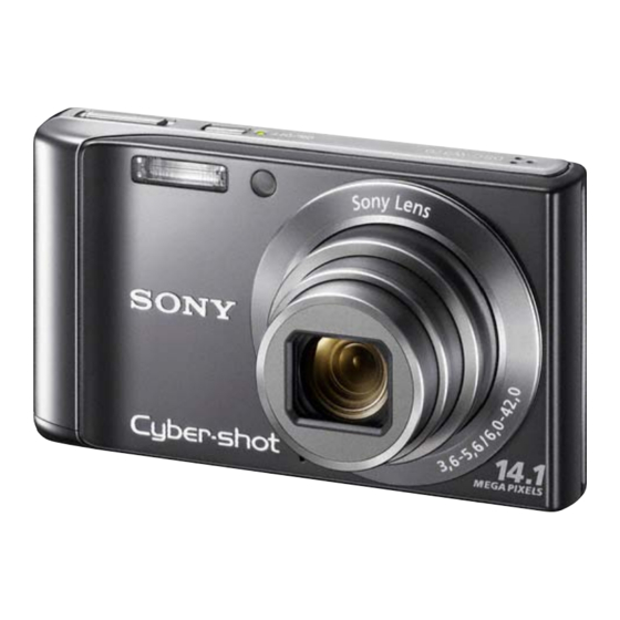
Sony DSC-W370 Service Manual
Digital still camera
Hide thumbs
Also See for DSC-W370:
- Instruction manual (523 pages) ,
- Handbook (128 pages) ,
- Specifications (2 pages)
Table of Contents
Quick Links
SERVICE MANUAL
Ver. 1.0 2010.01
Internal memory
Internal memory
ON BOARD
ON BOARD
SERVICE NOTE (Check the following note before the service.)
1-1. METHOD FOR COPYING OR ERASING THE DATA IN INTERNAL MEMORY
1-2. REGARDING FUSE
The components identified
Les composants identifiés par
by mark 0 or dotted line with
une marque 0 sont critiques
mark 0 are critical for safety.
pour la sécurité.
Replace only with part number
Ne les remplacer que par une
specified.
pièce portant le numéro spécifié.
DSC-W370
9-852-756-11
DSC-W370
Canadian Model
AEP Model
Australian Model
Photo: Silver
DIGITAL STILL CAMERA
Ver.
Date
1.0
2010.01
Official Release
US Model
UK Model
E Model
Sony EMCS Co.
Revision History
History
Contents
—
985275611.pdf
S.M. Rev.
issued
—
2010A2900-1
© 2010.1
Published by Tokai TEC
Table of Contents

Summary of Contents for Sony DSC-W370
- Page 1 0 sont critiques mark 0 are critical for safety. pour la sécurité. Replace only with part number Ne les remplacer que par une specified. pièce portant le numéro spécifié. 2010A2900-1 DSC-W370 © 2010.1 Sony EMCS Co. 9-852-756-11 Published by Tokai TEC...
- Page 2 Auto): Approx. 0.2 m to 5.0 m (W) (7 7/8 inches to 16 ft 4 7/8 inches) approx. 0.5 m to 3.2 m (T) (1 ft 7 3/4 inches to 10 ft 6 inches) DSC-W370 – 2 –...
-
Page 3: Safety Check-Out
ARE CRITICAL TO SAFE OPERATION. REPLACE THESE COMPO- CRITIQUES POUR LA SÉCURITÉ DE FONCTIONNEMENT. NE REM- NENTS WITH SONY PARTS WHOSE PART NUMBERS APPEAR AS PLACER CES COMPOSANTS QUE PAR DES PIÈCES SONY DONT SHOWN IN THIS MANUAL OR IN SUPPLEMENTS PUBLISHED BY LES NUMÉROS SONT DONNÉS DANS CE MANUEL OU DANS LES... -
Page 4: Service Note
Save precious data on a computer, etc. 1 MENU t (Settings) t (Memory Card Tool) or (Internal Memory Tool) t [Format] t [OK] t z on the control button Note • Note that formatting permanently erases all data including even protected images. DSC-W370 1-1E... -
Page 5: Repair Parts List
Back View Left View 8 Strobe Unit 7 LCD Module Front View Right View 6 LCD Bracket Bottom View 0 Lens Assy qa Main Frame Assy 2 Front Cabinet Assy Link DISCHARGING OF THE CHARGING CAPACITOR ACCESSORIES ACCESSORIES ASSEMBLY DSC-W370... -
Page 6: Note For Repair
R:1 k /1 W Preparing the Short Jig (Part code: 1-215-869-11) To preparing the short jig, a small clip is attached to each end of a resistor of 1 kΩ /1 W (1-215-869-11). Wrap insulating tape fully around the leads of the resistor to prevent electrical shock. Strobe Unit Wrap insulating tape. DSC-W370... - Page 7 X-2547-195-1 CABINET ASSY, FRONT (GREEN) X-2547-196-1 CABINET ASSY, FRONT (RED) 4-179-228-01 DC DOOR 4-179-226-01 MACHINE_M1.7_3_BLK_AB 4-179-227-01 MACHINE_M1.7_2.5_BLK_AB 4-179-234-01 STRAP PIN 4-179-231-01 MACHINE_M1.4_2_SVR_AB 4-179-230-01 JACK COVER X-2547-197-1 TOP COVER ASSY X-2547-189-1 CABINET ASSY, REAR (SILVER) X-2547-190-1 CABINET ASSY, REAR (BLACK) DSC-W370...
- Page 8 Main Frame Section (See Page 2-5) Ref. No. Part No. Description Ref. No. Part No. Description * 51 4-179-236-01 LCD BRACKET 4-179-231-01 MACHINE_M1.4_2_SVR_AB 4-179-233-01 SW BOARD 4-179-232-01 TAPPING_M1.4_3.5_SVR_AB X-2547-198-1 MODE DIAL ASSY 4-179-237-01 LCD MODULE * 55 4-179-235-01 TRIPOD SCREW DSC-W370...
- Page 9 FUSE, MICRO (1608 TYPE) (2A/32V) 4-179-239-01 STROBE UNIT (Note1) 0 F3 1-576-415-11 FUSE, MICRO (1608 TYPE) (2A/32V) 4-179-238-01 MAIN BOARD (Note2, 3) * 105 1-820-333-11 MULTI CONNECTOR (REC) 8P 4-179-232-01 TAPPING_M1.4_3.5_SVR_AB 4-180-525-01 CONNECTOR, HDMI C 1-822-837-21 CARD CONNECTOR A-1766-461-A LENS ASSY (Note4, 5) DSC-W370...
- Page 10 ∗ 4-176-402-51 (ENGLISH, FRENCH, ITALIAN, SPANISH, PORTUGUESE, GERMAN, DUTCH, TURKISH, GREEK, POLISH, CZECH, HUNGARIAN, SLOVAK, SWEDISH, FINNISH, NORWEGIAN, DANISH, CROATIAN, ROMANIAN) ∗ 4-176-402-61 (ENGLISH, TRADITIONAL CHINESE, SIMPLIFIED CHINESE, MALAY, INDONESIAN, THAI, ARABIC, PERSIAN) ∗ 4-176-402-71 (ENGLISH, TRADITIONAL CHINESE, SIMPLIFIED CHINESE, INDONESIAN, ARABIC, PERSIAN) Solder LED Lamp Harness DSC-W370 3-1E...
-
Page 11: Overall Block Diagram
4. BLOCK DIAGRAMS 4-1. OVERALL BLOCK DIAGRAM STROBE/BD K Battery 14 PIN soldering pad J9 VHLD Main/BD VSUB_C VOG1 G2102\power VOG2 SUB_CLK SONY CCD K Battery ICX681 detect IC 32.768KHz DSCIG Sensor/BD V8S2 V8S1 GPIO GPIO 3 in 1 ADDI9004...


